


FGS335E Q
SERVICE MANUAL
for the
FREESTANDING
SELF-CLEAN
GAS RANGE
LIT 4321891Printed in U.S.A.July, 1996

THIS MANUAL CONTAINS INFORMATION
NECESSARY FOR INSTALLING AND SERVICING
THE FOLLOWING FREESTANDING SELF-CLEAN
GAS RANGES, MODELS:
WHIRLPOOL
SF350BEE W SF375PEE Q/Z
SF360BEE W/N SF385PEE W/N
SF372BEE W/N SF385PEE Q/Z
SF372BEE Q/Z SF395LEE Q/Z/B
SF375PEE W/N
ROPER
FGS335E W/N
FGS335E Q
ESTATE
TGS325E W
THE MANUAL IS DESIGNED TO BE USED
ONLY BY QUALIFIED SERVICE PERSONNEL.
THE SERVICE INFORMATION IS ORGANIZED
TO HELP YOU EASILY FIND WHAT YOU NEED.
CHECK YOUR LOCAL BUILDING CODE FOR THE
PROPER MODE OF INSTALLATION. IN THE
ABSENCE OF LOCAL CODES, THIS UNIT
SHOULD BE INSTALLED IN ACCORDANCE WITH
THE
NATIONAL STANDARD, NATIONAL FUEL
GAS CODE ANSI Z223.1 — LATEST EDITION*.
* National Gas Association
1515 Wilson Boulevard
Arlington, Virginia 22209
- ii -
Cooking Products Service Manual
Original July, 1996 4321891
© 1996 Whirlpool Corporation
Page iii
Table of Contents
Page
Important Safety Information ........................................................................................................ v
Installation Highlights .......................................................................................................................1-1
Range Dimensions ......................................................................................................................1-1
Cabinet Dimensions ....................................................................................................................1-2
Tools & Material You Will Need ................................................................................................1-3
Electrical Supply Requirements ................................................................................................1-4
Gas Supply Requirements .........................................................................................................1-6
Installing The Range ...................................................................................................................1-7
Converting The Pressure Regulator & Maintop Burners For L.P. Gas............................. 1-10
Checking The Maintop Burner Operation ............................................................................. 1-13
Adjusting The Air Shutters .................................................................................................. 1-14
Converting The Oven Burners For L.P. Gas ........................................................................ 1-15
Checking the Oven Burner Operation ................................................................................... 1-16
Removing/Reinstalling The Oven Door ................................................................................. 1-20
Theory Of Operation .........................................................................................................................2-1
Component Access ...........................................................................................................................3-1
Removing The Maintop—Sealed Burner Models ....................................................................3-2
Removing The Maintop—Conventional Burner Models ......................................................... 3-4
Removing A Sealed Burner & A Venturi ..................................................................................3-5
Removing A Conventional Burner ............................................................................................. 3-6
Removing A Spark Ignitor Switch & Gas Valve ......................................................................3-7
Removing The Ignitor Module & A Burner Ignitor—Sealed Burner Models ........................ 3-8
Removing The Ignitor Module & A Burner Ignitor—Conventional Burner Models .......... 3-10
Removing The Oven Door Latch & Actuator Rod—Sealed Burner Models ..................... 3-12
Removing The Oven Door Latch & Actuator Rod—Conventional Burner Models .......... 3-14
Removing The Latch Sensing Switches, The Door Latch Solenoid,
& The Mechanical Latch....................................................................................................... 3-16
Removing The Upper Console................................................................................................ 3-18
Removing The Electronic Oven Control ................................................................................ 3-20
Removing An Oven Light Switch ............................................................................................ 3-21
Removing The Gas Safety Valve & Pressure Regulator .................................................... 3-22
Removing The Bake Burner & Ignitor .................................................................................... 3-23
Removing The Broil Burner & Ignitor..................................................................................... 3-24
Removing The Oven Temperature Sensor ........................................................................... 3-25
Removing A Side Panel ........................................................................................................... 3-26
Removing An Oven Light Socket ........................................................................................... 3-28
Removing The Oven Door Gasket ......................................................................................... 3-29
Removing The Oven Door Handle, Top Trim, & Outer Door Glass .................................. 3-30
Removing A Hinge Assembly.................................................................................................. 3-31
Removing The Inner Door Glass ............................................................................................ 3-33
Removing The Storage Drawer Glides .................................................................................. 3-34
- iii -

Page
Component Description & Testing .................................................................................................. 4-1
Troubleshooting ...........................................................................................................................4-1
Troubleshooting Chart ......................................................................................................... 4-11
Oven Temperature Calibration ............................................................................................... 4-13
Error Codes ............................................................................................................................... 4-13
Tech Tips ............................................................................................................................................5-1
Wiring Diagram 1 ......................................................................................................................... 5-1
Wiring Diagram 2 ......................................................................................................................... 5-2
Strip Circuits.................................................................................................................................5-3
Specifications ...............................................................................................................................5-5
Model And Serial Number Explanation ................................................................................. 5-20
Warranty .................................................................................................................................... 5-21
- iv -
IMPORTANT SAFETY INFORMATION
WARNING
This service manual is intended for factory-service
technicians only. We recommend that customers
DO NOT service their own units, because of the
complexity and risk of high-voltage electrical shock.
The following information is used throughout this
manual, and should be read carefully.
NOTE
Helpful information that explains a more complicated step, prior to carrying it out .
Cooking Products Service Manual
Original July, 1996 4321891
© 1996 Whirlpool Corporation
Fire Hazard
Do not obstruct the flow of combustion and
ventilation air.
Electrical Shock Hazard
It is the customer’s responsibility to:
• Contact a qualified electrical installer.
• Assure that electrical installation is adequate
and in conformance with the National Electrical Code, ANSI/NFPA 70—latest edition*,
and all local codes and ordinances.
Page v
CAUTION
Information that will help you avoid actions
that could cause product damage (scratches,
dents, etc.) and damage to personal property.
WARNING
Information that alerts you to potentially dangerous conditions. These conditions can
cause serious personal injury (burns, fire and
electrical shock, etc.) if the suggested procedures are not observed.
WHIRLPOOL CORPORATION ASSUMES NO RE-
SPONSIBILITY FOR ANY REPAIRS MADE ON
OUR PRODUCTS BY ANYONE OTHER THAN
AUTHORIZED WHIRLPOOLSM SERVICE TECH-
NICIANS.
Failure to do so could result in fire, electrical
shock, or other personal injury.
Take special care when drilling holes into the
wall for venting or electrical wiring. Electrical
wires may be concealed behind the wall covering.
Failure to do so could result in fire, electrical
shock, or other personal injury.
* National Fire Protection Association
Batterymarch Park
Quincy, Massachusetts 02269
- v -
WARNING
To reduce the risk of fire, electrical shock,
injury to persons, or damage when using
the range, follow these basic precautions:
1. Read all instructions before using the
range.
2. Install or locate the range only in accordance with the provided installation instructions. It is recommended that the
range be installed by a qualified installer.
The range must be properly connected to
the correct gas supply and checked for
leaks. The range must also be properly
connected to a grounded electrical supply.
3. Gas fuels and combustion can result in
potential exposure to chemicals known to
cause cancer or reproductive harm. For
example, benzene is a chemical which is
a part of the gas supplied to the range. It
is consumed in the flame during combustion. However, exposure to a small amount
of benzene is possible if a gas leak occurs. Formaldehyde and soot are by-products of incomplete combustion. Properly
adjusted burners with a bluish rather than
a yellow flame will minimize incomplete
combustion.
4. Do not use the range for heating the room.
Persons could be burned or injured, or a
fire could start.
5. Do not leave children alone or unattended
in area where the range is in use. They
should never be allowed to sit or stand on
any part of the range. They could be
burned or injured.
6. Do not wear loose or hanging garments
when using the range. Clothing could ignite if it touches a surface burner and you
could be burned.
7. Do not repair or replace any part of the
range unless specifically recommended
in this manual. All other servicing should
be referred to a qualified technician.
8. Do not operate the range if it is not working properly, or if it has been damaged or
dropped.
9. Know where your main gas shut off valve
is located.
10. Clean your range regularly. See “Care
and Cleaning” instructions that are included with the range.
11. Use the range only for its intended use as
described in this manual.
12. Do not store flammable materials on or
near the range. They could explode or
burn.
13. Do not use water on grease fires. Never
pick up a flaming pan. Smother flaming
pan on range by covering with a wellfitting lid, cookie sheet or flat tray. Flaming grease outside of pan can be extinguished with baking soda, or if available,
a multipurpose dry chemical or foam-type
extinguisher.
14. Use only dry potholders. Moist or damp
potholders on hot surfaces may result in
burns from steam. Do not let potholder
touch an open flame. Do not use a towel
or bulky cloth for a potholder. It could
catch on fire.
15. Make sure the utensils you use are large
enough to contain food and avoid boilovers
and spillovers. Heavy splattering or
spillovers left on a range can ignite and
burn you. Pan size is especially important
in deep fat frying.
16. Never leave burners unattended at high
flame settings. A boilover could result
and cause smoking and greasy spillovers
that may ignite.
- vi -

Cooking Products Service Manual
Original July, 1996 4321891
© 1996 Whirlpool Corporation
Page vii
17. Grease is flammable and should be
handled carefully. Let fat cool before attempting to handle it. Do not allow grease
to collect around range or in vents. Wipe
spillovers immediately.
18. Check to be sure glass cooking utensils
are safe for use on the range. Only certain
types of glass, glass-ceramic, earthenware or other glazed utensils are suitable
for ranges. Other types may break due to
the sudden change in temperature.
19. Turn pan handles inward, but not over
other burners. This will help reduce the
chance of burns, igniting of flammable
materials, and spills due to bumping the
pan.
20. Do not heat unopened containers. They
could explode. The hot contents could
cause burns and container particles could
cause injury.
21. Do not use decorative covers or trivets
over the surface burners.
22. Do not store things children might want
above the range. Children could be burned
or injured while climbing on range.
23. Do not touch hot burners or areas near
burners. Areas near burners become hot
enough to cause burns. During use, do
not touch or let clothing or other flammable materials contact burners, or areas near burners.
24. Do not block the ventilation.
25. Never use a match or other flame to look
for a gas leak. Explosion and injury could
result.
26. Make sure the burners are off when you
are finished, and when you are not watching.
27. Be sure all range parts are cool before
cleaning.
- vii -

— NOTES —
- viii -

Cooking Products Service Manual
Original July, 1996 4321891
© 1996 Whirlpool Corporation
INSTALLATION HIGHLIGHTS
RANGE DIMENSIONS
Page 1-1
GENERAL
Proper installation is your responsibility. A qualified technician must install this range. Make sure
you have everything necessary for correct installation. It is the responsibility of the installer to comply
with the installation clearances specified on the
oven model/serial rating plate. This plate is located
on the frame behind the storage door panel. IM-
PORTANT: Be sure to observe all governing codes
and ordinances. In the absence of local codes,
installation must conform with American National
Standard, National Fuel Gas Code ANSI Z223.1 —
latest edition*.
* American Gas Association
1515 Wilson Boulevard
Arlington, Virginia 22209
The dimensions of the range are shown below.
Check the location where the range will be installed. The location should be away from strong
draft areas, such as windows, doors, and strong
heating vents or fans. The range should be located
for convenient use in the kitchen.
ALL OPENINGS IN THE WALL OR FLOOR ARE
TO BE SEALED AFTER THE RANGE IS INSTALLED.
MOBILE HOME INSTALLATION
The installation of this range must conform with the
Manufactured Home Construction and Safety Standard, Title 24 CFR, Part 3280 (formerly the Federal
Standard for Mobile Home Construction and Safety,
Title 24, HUD, Part 280), or when such standard is
not applicable, the Standard for Manufactured
Home Installations, ANSI A225.1/NFPA 510A, or
with local codes.
When this range is installed in a mobile home, it
must be secured to the floor during transit. Any
method of securing the range is adequate as long
as it conforms to the standards listed above.
Copies of standards listed may be obtained from:
National Fire Protection Association
Batterymarch Park
Quincy, Massachusetts 02269
27-1/8" depth
with handle
24-13/16
46-7/8
"
overall
height
36
"
cooktop
height
"
29-7/8" width
1-1
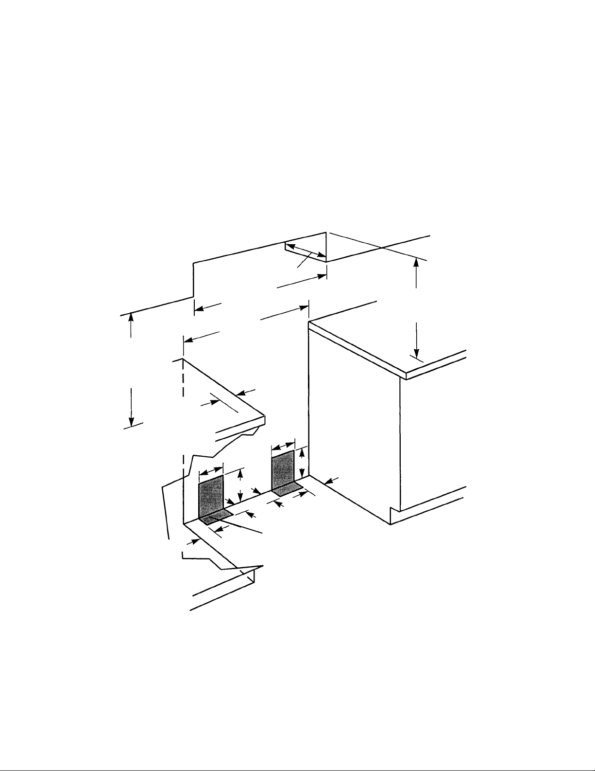
CABINET DIMENSIONS
Use only the cabinet opening dimensions that are
shown below. The dimensions shown are for minimum clearances.
A grounded electrical outlet is required (see page
1-4).
A proper gas supply connection must be available
(see page 1-6).
max. upper
cabinet depth
"
min.
30
cabinet opening width
1
/8" min.
30-
opening width
18
"
min.
clearance upper
cabinet to
countertop
2" minimum
countertop
space to side
wall or other
combustible
material
8
Contact a qualified
floor covering installer
to check that the floor
covering can withstand
at least 90˚F above
room temperature.
Use an insulated
pad, or 1/4" plywood
under the range if
installing the range
over carpeting.
The Anti-Tip bracket MUST be
installed. (See page 1-7 for
details.)
4-1/2
"
"
17
"
2
"
This shaded area shown in the illustration is the recommended area for
installation of rigid gas pipe.
Flexible gas pipe and an electrical
outlet are recommended in either
shaded area.
Do not pinch the power cord between the range and the wall when
you push the range into its mounting location.
Clearance Note:
A clearance of 30" minimum is
required when the bottom of a wood or metal
1
cabinet is protected by not less than
/4" of flameretardant millboard covered with not less than #28
MSG sheet steel, 0.015
stainless steel, 0.024
"
"
aluminum, or 0.020" copper. A minimum clearance
"
between the top of the cooking platform and
of 36
the bottom of an unprotected wood or metal cabinet is required.
13
"
Refer to
“Clearance
Note” above.
Do not seal the range to
the side cabinets.
If the cabinet depth
is greater than 24", the
oven frame must extend
beyond the cabinet
8
"
17
"
4-1/2
"
2
"
front by 1/2" minimum.
1-2
Cooking Products Service Manual
Original July, 1996 4321891
© 1996 Whirlpool Corporation
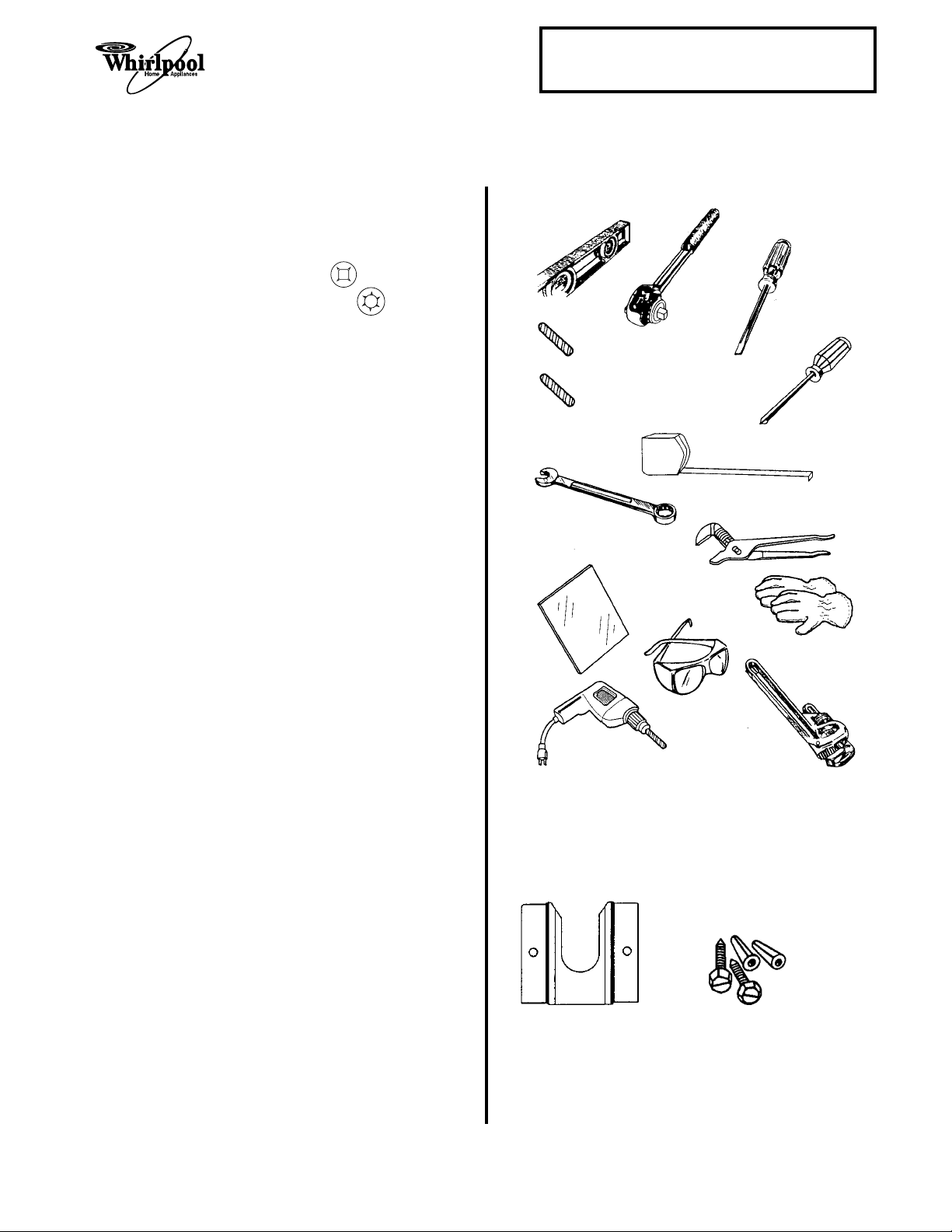
TOOLS & MATERIAL YOU WILL NEED
Page 1-3
TOOLS
Standard (flat-bladed) screwdriver
Phillips screwdriver
Robertson (S2) screwdriver
Torx (T10 & T20) screwdrivers
Spirit level
Pipe wrench
Channel lock pliers
Measuring tape
3
/8" ratchet drive
Hand or electric drill
1
/8" wood drill bit or 3/16" carbide-tipped
masonry drill bit
15
/16" , 1/2", & 3/8" combination wrench
Mirror
Safety glasses
Gloves
ADDITIONAL MATERIAL
ILLUSTRATIONS
spirit level
3/8" ratchet
drive
wood floor:
1/8" drill bit
concrete/ceramic floors:
3/16" carbide-tipped
masonry drill bit
15/16", 1/2" and
3/8" combination
wrench
mirror
flat-blade
screwdriver
Phillips
screwdriver
tape measure
or ruler
channel lock
pliers
gloves
Gas line shutoff valve
1
/2" male pipe thread for connection to pressure
regulator
L.P. gas-resistant pipe-joint compound
A.G.A. design-certified flexible metal connector
(4 to 5 feet), or rigid gas supply line
1
Insulated pad or
/4" plywood, if range is installed
over carpeting
PARTS SUPPLIED
1 Anti-tip bracket
2 Plastic anchors
2 Screws (#10 x 1-
ness of the flooring may require longer
screws. These are available at your local
hardware store.
1
/2" ) NOTE: The thick-
hand or
electric drill
ANTI-TIP BRACKET
safety glasses
pipe wrench
#10 X 1-1/2" SCREWS
PLASTIC
ANCHORS
1-3
ELECTRICAL SUPPLY REQUIREMENTS
WARNING
Electrical Shock Hazard
An electrical ground is required on this appliance.
If a cold water pipe is interrupted by plastic,
nonmetallic gaskets, or other insulating materials, do not use for grounding.
Do not ground to a gas pipe.
Do not change the power supply cord plug. If the
plug will not fit the outlet, have a proper outlet
installed by a qualified electrician.
Do not use a fuse in the neutral or grounding
circuit. It could result in an electrical shock.
Do not use an extension cord with this range.
Check with a qualified electrician if you are in
doubt as to whether the appliance is properly
grounded.
Failure to follow these instructions could result in
serious injury or death.
The following information applies to the gas range
wiring:
• A 3-wire, single phase, 120-volt, 60 Hz, AC-
only electrical supply is required on a separate 10-ampere circuit, fused on both sides of
the line. A time-delay fuse, or circuit breaker,
is recommended. The fuse must be sized as
per local codes in accordance with the electrical rating of the appliance specified on the
model/serial rating plate, which is located on
the frame behind the storage door panel.
• The gas range must be connected with cop-
per wire only.
• Wire sizes and connections must conform to
the requirements of the National Electrical
Code, ANSI/NFPA 70—latest edition*, and all
local codes and ordinances. Wire sizes and
connections must conform with the rating of
the appliance. Copies of the standards listed
above may be obtained from:
National Fire Protection Association
*
Batterymarch Park
Quincy, Massachusetts 02269
Equipment & Property Damage
Use a separate power line for this gas range,
and make sure that you connect it to the proper
voltage source. Failure to do so could result in
improper operation, equipment, or property damage.
GENERAL
If codes permit, and a separate grounding wire is
used, it is recommended that a qualified electrician
determine that the grounding path is adequate.
• The gas range should be connected directly
to the fused disconnect (or circuit breaker)
through flexible, armored, or nonmetallic
sheathed, copper cable. The flexible, armored
cable that extends from the appliance should
be connected directly to the junction box.
• Locate the junction box to allow as much slack
as possible between the junction box and the
appliance so that the appliance can be moved
if servicing is ever necessary. Do not cut the
conduit.
1
• A U.L.-listed,
provided at the junction box.
• A wiring diagram is located in the “Tech Tips”
(Section 5) of this manual.
/2" conduit connector must be
1-4
WARNING
Personal Injury/Fire Hazard
Do not, under any circumstances, cut or remove the grounding prong from the range cord.
Failure to provide proper polarization may cause
shock and fire hazard.
ELECTRONIC IGNITION SYSTEM
Cooking Products Service Manual
Original July, 1996 4321891
© 1996 Whirlpool Corporation
Page 1-5
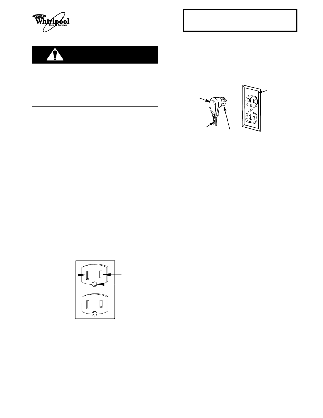
Once you are sure that the plug is polarized properly, perform the next step.
2. Connect the power cord plug on the gas range
to a 120-volt AC receptacle that is on a separately fused line.
3-PRONG
GROUNDING-
3-PRONG
GROUNDING PLUG
TYPE WALL
RECEPTACLE
When connecting an appliance that has an electronic ignition system to a 120-volt AC receptacle, it
is very important that the receptacle wiring is correctly polarized and properly grounded. If the plug is
not polarized properly, the ignitor module will not
operate correctly.
1. The 120-volt AC receptacle should use 3wires, and be polarized with two plug slots
and a round grounding pin. Proper wiring for
this type of receptacle is as follows:
a) The white wire is connected to the neutral
side of the plug.
b) The black wire is connected to the hot
(120-volt ac) side of the plug.
c) The green, or bare wire is connected to
the round grounding pin of the plug.
3-WIRE
AC RECEPTACLE
WHITE
BLACK
POWER SUPPLY
CORD
GROUNDING PRONG
GREEN
1-5
GAS SUPPLY REQUIREMENTS
WARNING
Fire Hazard
The gas appliance must be connected to a
regulated gas supply.
Do not use an open flame to test for gas leaks
from gas connections.
New A.G.A.-designed and certified flexible gas
line should be used, when codes permit.
Do not store or use gasoline, or any other
flammable vapors and liquids, in the vicinity of
this, or any other appliance.
If you smell gas:
• Do not light any appliance.
• Do not operate any electrical switches.
• Do not use the telephone.
• Call the gas supplier immediately from a
neighbor’s telephone, and follow the gas
supplier’s instructions carefully.
• If you cannot reach the gas supplier, call the
fire department.
Failure to follow these instructions could result in
fire, explosion, or other personal injury.
This range is factory set for use with natural gas. It
is designed-certified by the American Gas Association (A.G.A.) for natural or L.P. gases with the
appropriate conversion. The model/serial rating
plate has information on the type of gas that can be
used. If the type of gas listed does not agree with
the type of gas available, check with the local gas
supplier. Conversion must be done by a qualified
service technician.
3
A rigid,
both natural and L.P. gas at the gas range installation location. Long lengths of smaller size pipe may
result in an insufficient supply of gas to the range.
Pipe-joint compounds, made for use with natural
and L.P. gas, must be used.
If local codes and ordinances permit, new A.G.A.approved, flexible metal tubing can be used for
connecting the appliance to the gas supply line. Do
not kink or damage the flexible tubing when moving
the appliance. A
connecting to the female pipe threads of the pressure-regulator.
/4" gas supply pipe, must be provided for
3
/4" male pipe thread is needed for
GENERAL
This installation must conform with local codes and
ordinances. In the absence of local codes, installation must conform with the American National
Standard, National Fuel Gas Code ANSI Z223.1—
latest edition.*
Copies of the standards listed above may be obtained from:
* American Gas Association
1515 Wilson Boulevard
Arlington, Virginia 22209
Input ratings shown on the model/serial rating plate
(located on the frame behind the storage door
panel) are for elevations up to 2,000 feet. For
elevations above 2,000 feet, contact the local service company.
The supply line must be equipped with an approved shutoff valve. This valve should be located
in the same room as the appliance, and should be
in a location that allows easy access to turn the gas
supply on and off. Do not block the access to the
shutoff valve. Never reuse an old connector
when installing a new range.
1-6
INSTALLING THE RANGE
WARNING
Electrical Shock Hazard
Take special care when drilling holes in the
floor or wall. Electrical wires may be behind the
wall or floor covering and could cause an
electrical shock if you touch them.
Locate the electrical circuits that could be affected by the installation of the anti-tip bracket
and turn off power to these circuits.
Cooking Products Service Manual
Original July, 1996 4321891
© 1996 Whirlpool Corporation
5. Remove the cardboard shipping base from
under the range.
6. Remove the storage drawer from the range.
3
7. Using a
ing legs
/8" drive ratchet, lower the rear level-
1
/2 -turn.
front leveling leg
Page 1-7
Personal Injury Hazard
To reduce the risk of tipping of the range, the
range must be secured by a properly installed
floor-mounted anti-tip bracket, supplied with
the range.
If range is moved to a new location, the anti-tip
bracket must be reinstalled in the new location.
Because of the weight and size of this range,
two or more people are required to move it.
Do not use the handle for lifting.
Failure to follow these instructions could result
in injury.
INSTALLING THE ANTI-TIP
BRACKET
1. Use safety glasses and gloves to install the
range.
2. Remove the oven racks and parts package
from inside the oven. Also remove all shipping
materials, tape, and protective film from the
range.
3. Slide a cardboard shipping base under the
range to prevent damage to the floor covering.
4. Use the anti-tip bracket template/instruction
sheet, and install the anti-tip bracket. The
anti-tip bracket must be anchored securely to
the sub floor. Depending on the thickness of
the flooring, longer screws may be needed to
anchor the bracket to the sub floor.
rear leveling leg
8. Use channel lock pliers and lower the front
leveling legs
9. Carefully move the range to its final operating
location. Make sure that the rear leveling leg
is engaged in the anti-tip bracket .
10. If you are installing the range in a mobile
home, secure the range to the floor. Use a
method that complies with the standards in
the “Mobile Home Installation” instructions on
page 1-1.
11. Place the racks in the oven, then place a level
on a rack, and check to make sure that the
range is level. Readjust the legs, as necessary. NOTE: For proper baking conditions,
the range must be level.
1
/2 -turn.
slide leg in anti-tip bracket
1-7
WARNING
Fire Hazard
pressure regulator
When you make gas line connections, especially to the pressure regulator, do not make the
connections too tight. If you do, you may crack
the regulator (or pipe) and cause a gas leak,
which could result in a possible fire, or explosion.
INSTALLING THE GAS LINE
The following procedure is for a typical gas line
installation and its associated components to the
gas range. Use pipe-joint compound that is made
for use with natural and L.P. gas to seal all of the
connections. Tighten all of the connections with an
adjustable (pipe) wrench.
1. Turn all of the range knobs to OFF.
2. Remove the storage drawer so you can access the regulator.
3. Remove the plastic dust cap from the inlet of
the pressure regulator.
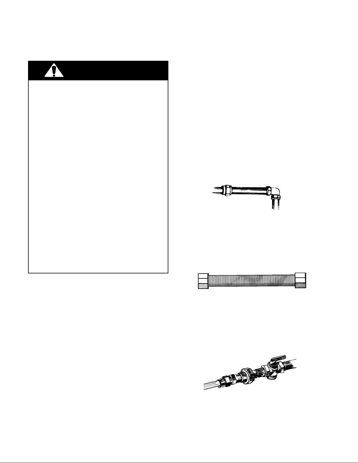
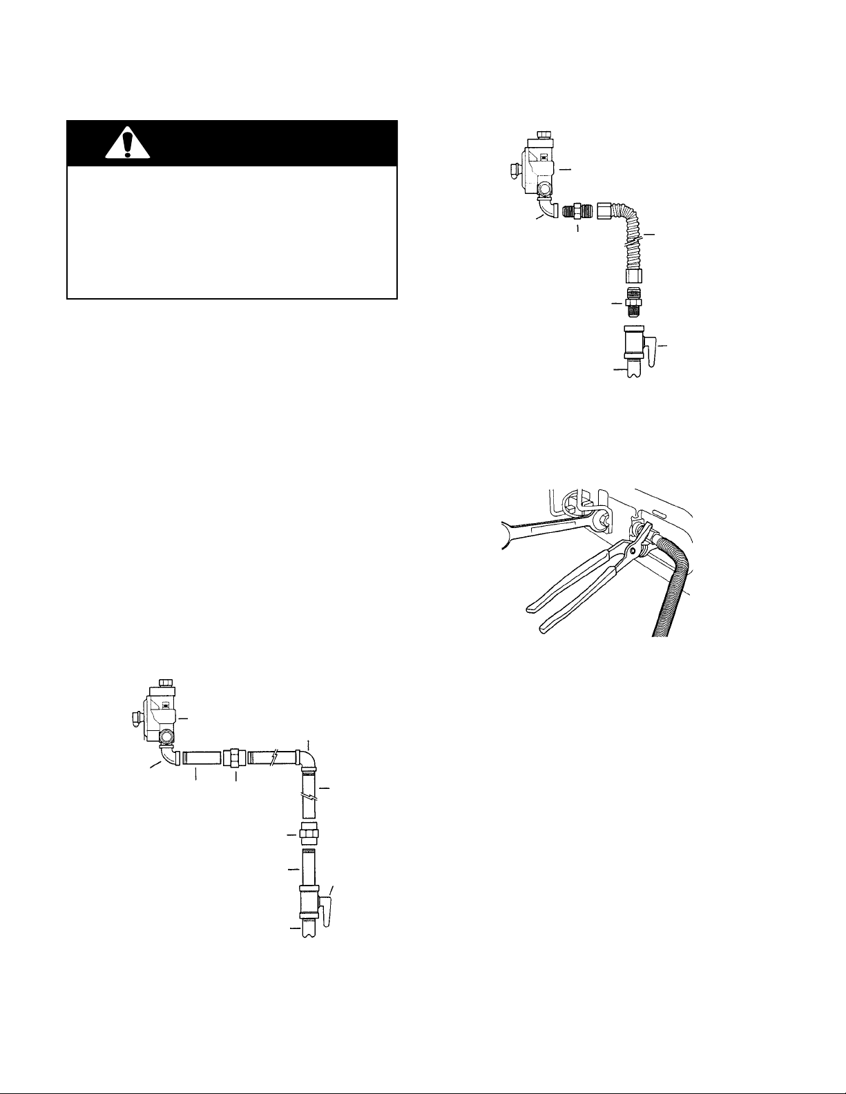
4. Assemble the rigid or flexible gas line between the gas supply pipe and the pressure
regulator. Typical installations are shown in
the following two illustrations. Use pipe-joint
compound that is made for L.P. gas to seal the
connections.
90˚ elbow
adapter
adapter
1/2" to 3/4
gas pipe
A Typical Flexible Gas Line
flexible line
gas shutoff valve
"
5. Use a 15/16" combination wrench and channel
lock pliers and tighten all of the fittings securely.
6. Seal all of the openings in the floor or wall
around the range installation.
90˚ elbow
pressure regulator
90˚ elbow
nipple union iron pipe
union
nipple
1/2" to 3/4
gas pipe
A Typical Rigid Gas Line
gas shutoff
valve
"
1-8
Cooking Products Service Manual
Original July, 1996 4321891
© 1996 Whirlpool Corporation
Page 1-9
CHECKING FOR LEAKS
WARNING
Fire Hazard
Turn off the main gas supply before you try to
stop a leak.
Be sure that all leaks are stopped before lighting
pilots or burners.
Do not use an open flame to test for gas leaks.
Failure to follow these instructions could result in
a possible fire, or explosion.
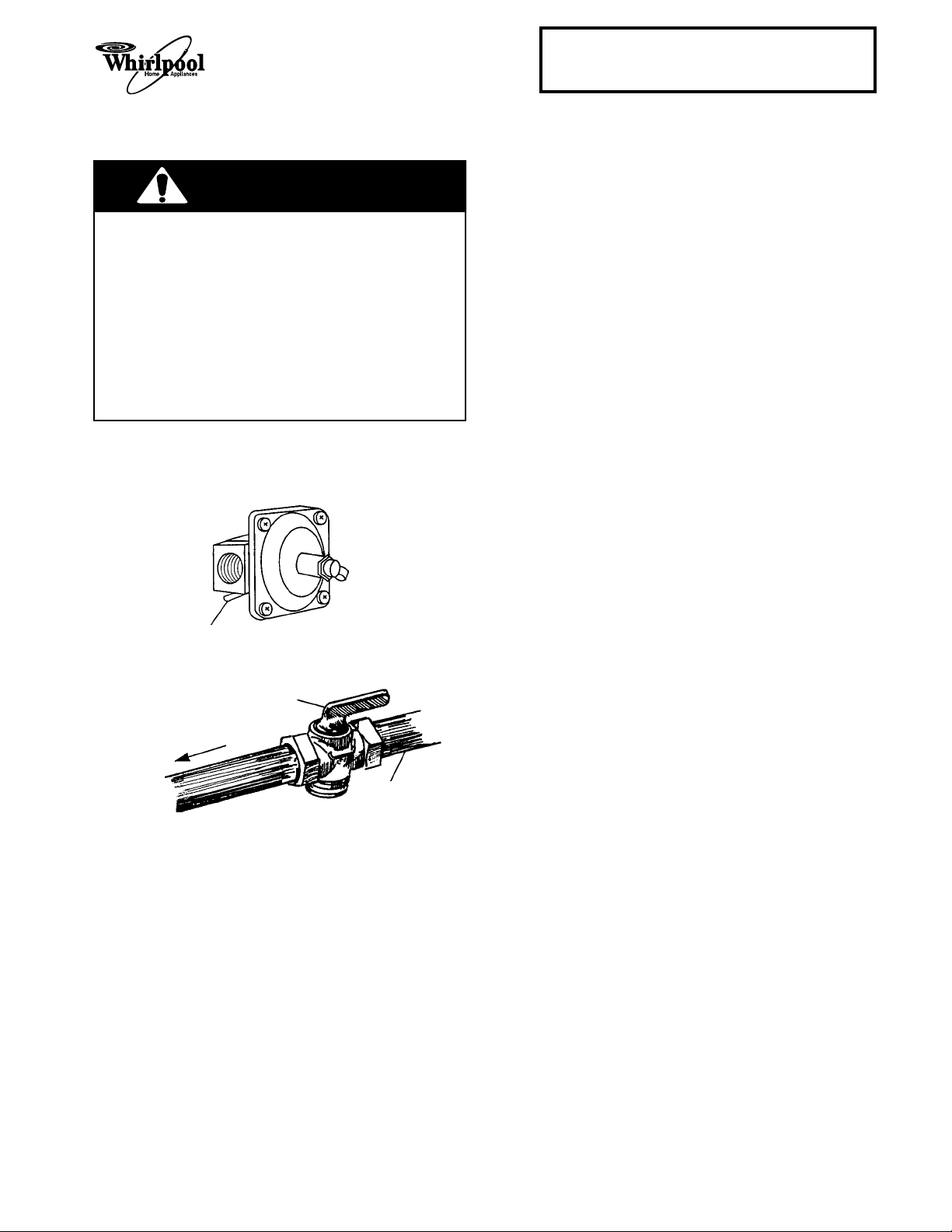
1. Make sure that no open flame is present, then
open the gas line shutoff valve and the regulator shutoff valve.
regulator shutoff valve
to “open” position
CHECKING THE PRESSURE
REGULATOR
The pressure regulator must be checked at a
"
minimum 1
The inlet pressure to the regulator should be set as
follows:
a) Set the minimum pressure using natural
b) Set the maximum pressure at 14".
For testing the line pressure above
pressure gauge:
a) Disconnect the appliance and its individual
For testing the line pressure @
a pressure gauge:
a) Close the gas supply shutoff valve to the
NOTE: If you are converting the range for L.P. gas,
proceed to the next page. If not, proceed to “Checking The Maintop Burner Operation” on page 1-13.
water column above the set pressure.
gas @ 5
and for L.P. gas @ 11
".
1
/2 psi with a
"
shutoff valve from the gas supply when the
1
pressures are greater than
/2 psi (3.5 kPa).
1
/2 psi or lower with
appliance when the pressures are equal to,
1
or less than
/2 psi (3.5 kPa).
open gas line
shutoff valve
to range
gas supply
2. Turn one of the burner gas valves on until the
air in the line is expelled and gas begins to
flow out the burner, then turn the valve off.
3. Use a brush and liquid detergent and check all
the connections for possible leaks. If bubbling
occurs around the joint, tighten the connection further until the bubbling just stops. Do
not overtighten the connection.
1-9
CONVERTING THE PRESSURE REGULATOR &
MAINTOP BURNERS FOR L.P. GAS
THE PRESSURE REGULATOR
WARNING
Personal Injury Hazard
Do not operate the burners of this range when
using L.P. (bottled) gas before converting the
pressure regulator, burner orifices, and oven
pilot adjustment screw (if applicable), for L.P.
gas usage.
Failure to follow these instructions could result
in high flames and toxic fumes, causing serious
injury.
Fire Hazard
Shut off the gas supply line valve.
Make all conversions before turning gas supply
valve back on.
Failure to follow these instructions could result
in explosion, fire, or other injury.
1. Remove the storage drawer from the range.
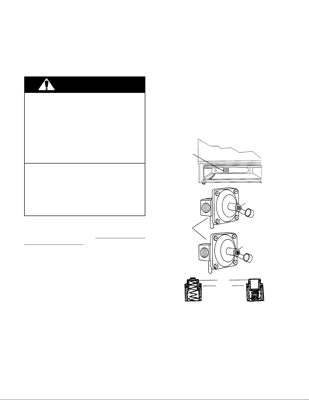
2. Remove the plastic cover from the pressure
regulator.
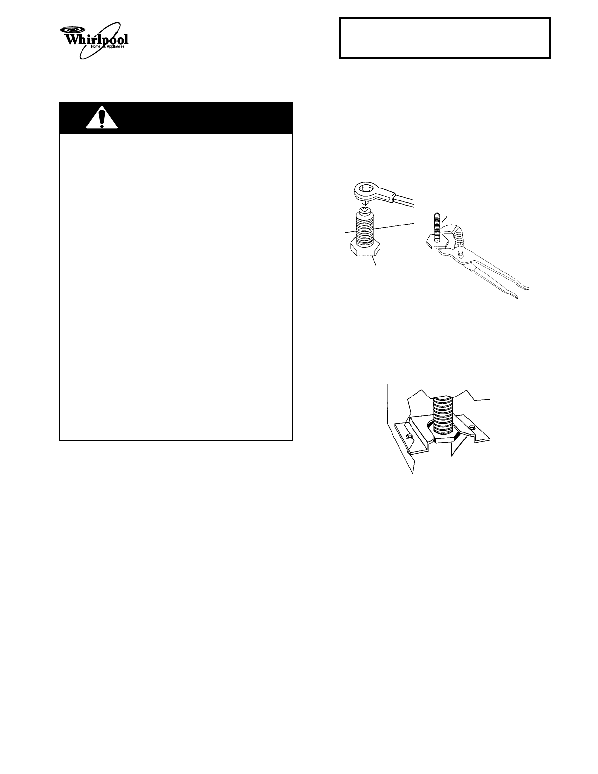
3. Use a wrench, and turn the cap marked “N” on
the front of the pressure regulator counterclockwise, and remove it. NOTE: Do not disturb the spring under the cap.
L.P.
4. Turn the cap over so that the letters
visible and reinstall it into the regulator.
5. Reinstall the plastic cover on the pressure
regulator.
Pressure Regulator
Natural Gas
are
Conversions to the pressure regulator and burner
orifices for L.P. gas usage must be done by a
qualified service technician.
regulator to convert it.
To convert the regulator from natural to L.P. gas,
use the following procedure:
Do not remove the
Pressure Regulator
Natural Gas
L.P. Gas
cap
washer
L.P. Gas
1-10
Cooking Products Service Manual
LEFT VENTURI
RIGHT VENTURI
Original July, 1996 4321891
© 1996 Whirlpool Corporation
Page 1-11
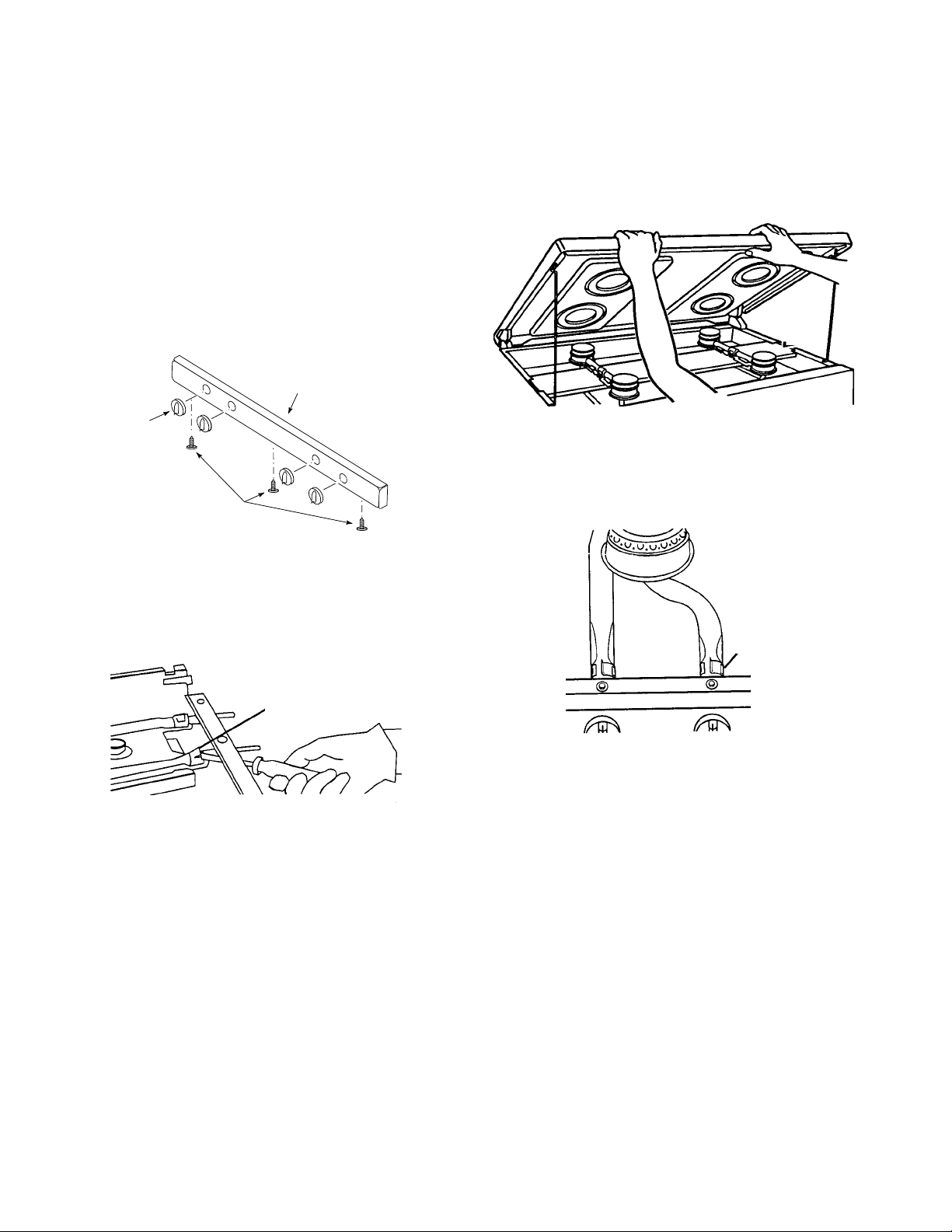
SEALED BURNERS
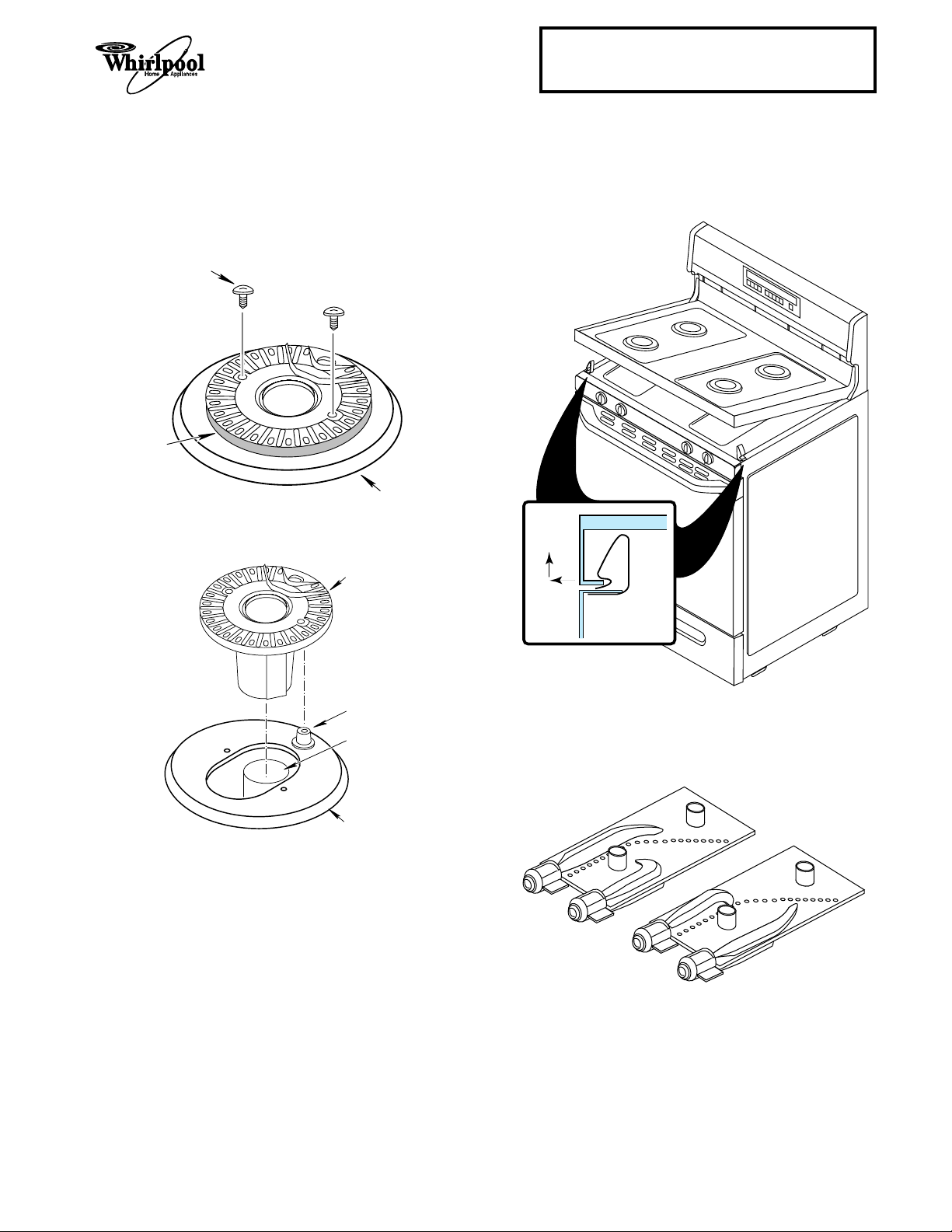
1. Remove the grates and burner caps from the
burners.
2. Remove the screws from each of the four
burners.
SCREW
BURNER
MAINTOP
3. Lift each burner off the venturi and burner
ignitor.
BURNER
4. Push the front of the maintop to the right while
lifting the right corner and unclip it, then push
to the left and unclip the left corner. Lift the
front of the maintop and prop it up.
PUSH TO
SIDE AND
LIFT TO
UNCLIP
MAINTOP
CLIP
BURNER
IGNITOR
VENTURI
MAINTOP
SIDE PANEL
5. Remove the left and right venturi from the
burner box.
1-11
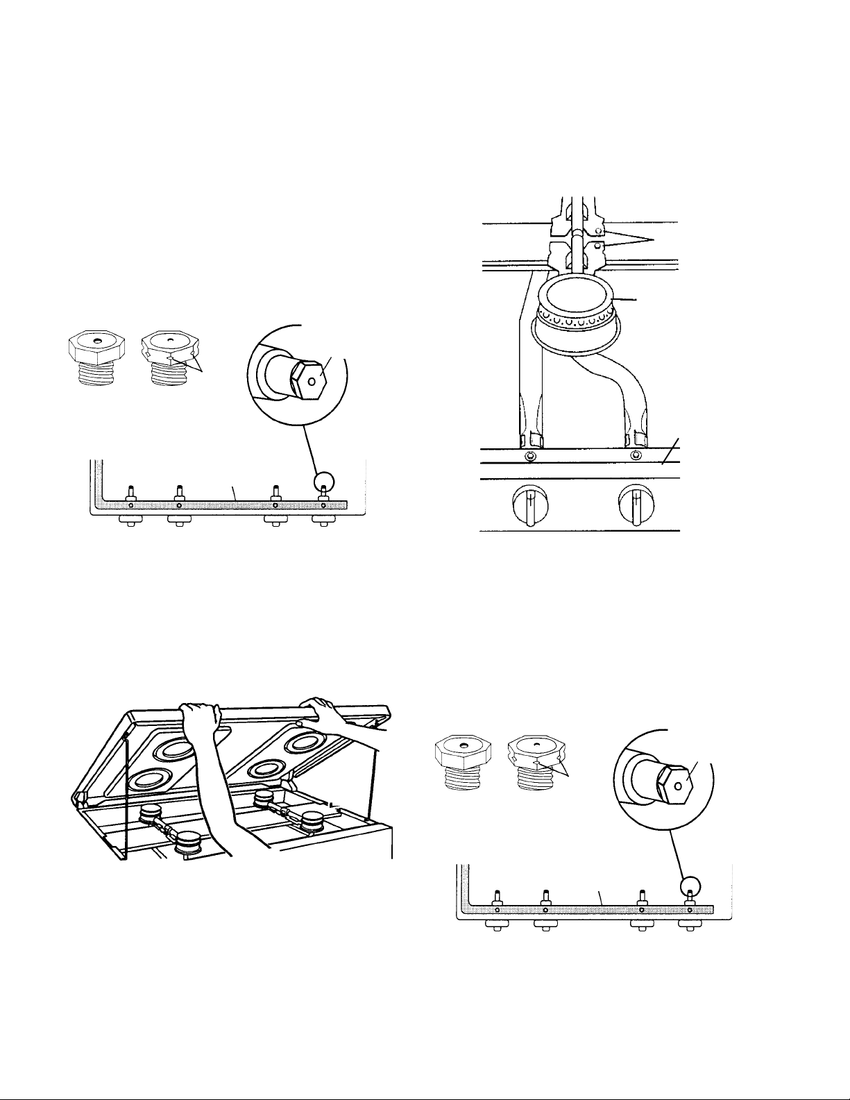
6. Removing one orifice spud at a time, use a
3
/8" combination wrench, and replace the four
color-coded natural gas orifice spuds with the
same color L.P. gas orifice spuds. NOTE:
When you are finished, place the natural gas
orifice spuds in a plastic bag, and store them
in a safe place for possible future use. Also,
keep the literature that was supplied with the
orifice spuds, in the same bag.
3. Remove the four burners from the burner
support bracket and from over the gas valves.
NOTE: If installed, remove the shipping screws
from the burners before you remove them.
burner shipping
screw
Remove and
orifice spuds
notches
#70 #65 gas #65 #68
black brass manifold brass nickel
L.R. L. F. R. F. R.R.
7,500 BTU 8,500 BTU 8,500 BTU 6,500 BTU
replace the
orifice spuds
with the same
color spuds.
7. Reassemble the range.
CONVENTIONAL BURNERS
1. Remove the grates from the burners.
2. Lift the maintop until the support rods lock .
burner
gas valve
4. Removing one orifice spud at a time, use a
3
/8" combination wrench, and replace the natural gas orifice spuds with the L.P. gas orifice
spuds. NOTE: When you are finished, place
the natural gas orifice spuds in a plastic bag,
and store them in a safe place for possible
future use. Also, keep the literature that was
supplied with the orifice spuds, in the same
bag.
orifice spuds
Remove and
replace the
orifice spuds.
notches
brass brass brass brass
L.R. L. F. R. F. R.R.
9,500 BTU 9,500 BTU 9,500 BTU 9,500 BTU
gas manifold
5. Reassemble the range.
1-12
Cooking Products Service Manual
Original July, 1996 4321891
© 1996 Whirlpool Corporation
Page 1-13
CHECKING THE MAINTOP BURNER OPERATION
1. Install the maintop burner caps on the burners.
2. If not already done, turn on the gas and
electrical supplies to the range.
3. Push and turn each of the maintop burner
knobs to the LITE position. You should hear a
snapping sound as the burner ignitors spark.
The gas at each burner should ignite after
approximately 4-seconds. When this occurs,
turn the knob to the HI setting. NOTE: Do not
leave the knob in the LITE position after the
burner lights, otherwise the ignitors will continue to spark.
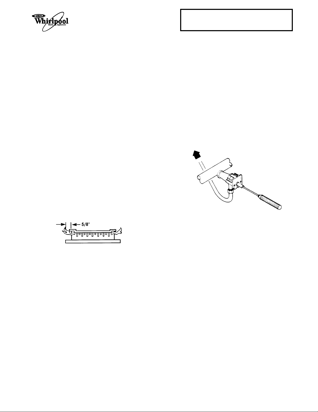
4. Check the maintop burners for the proper
flame. The small inner cone should have a
very distinct blue flame that is approximately
5
/8" long. The outer cone will not be as distinct
as the inner cone. If the flame is noisy or is
blowing, there is too much air during combustion. If the flame is soft and not high enough,
there is not enough air. If either of these
conditions occur, adjust the air shutters, as
shown on the next page.
LO F LAME SETTING
ADJUSTMENT (SOME MODELS)
Some gas ranges have a low flame burner adjustment, located inside the shaft of each gas valve
(see the illustration below). To adjust the flame:
1. Turn the gas valve knob to its LOW, or SIMMER setting, and remove the control knob.
2. Adjust the screw inside the gas valve stem so
that the flame size is as small as possible
without going out when the valve is turned
quickly from the LITE position to WARM position.
3. Turn off the burners and reinstall the knob.
5. Turn the maintop burners off.
1-13
Adjusting The Air Shutters
SEALED BURNERS
1. Lift the maintop and prop it up (see page 1-11
for the procedure).
2. Remove the control knobs.
3. Open the oven door and remove the three
screws from the bottom of the manifold panel,
then pull down slightly on the panel, and pull
it away from the range.
MANIFOLD PANEL
KNOB
SCREWS
4. Use a screwdriver blade, and adjust the air
shutter, as needed. Close the air shutter to
decrease the amount of air to the flame. Open
the air shutter to increase the amount of air to
the flame.
CONVENTIONAL BURNERS
1. Lift the maintop until the support rods lock.
2. Adjust the air shutter openings, as needed.
Close the air shutter to decrease the amount
of air to the flame. Open the air shutter to
increase the amount of air to the flame.
air shutter
venturi air shutter
5. Replace the manifold panel and control knobs
and lower the maintop.
3. Lower the maintop.
1-14
Cooking Products Service Manual
Original July, 1996 4321891
© 1996 Whirlpool Corporation
Page 1-15
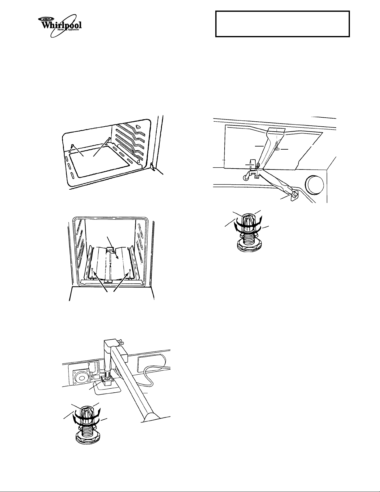
CONVERTING THE OVEN BURNERS FOR L.P. GAS
THE BAKE BURNER
1. Remove the oven racks.
2. Remove the two screws from the oven floor
and remove the floor.
screws
3. Remove the screws from the heat shield over
the bake burner and remove the shield.
heat shield
THE BROIL BURNER
1. Remove the oven racks.
2. Remove the two screws (shown in the illustration) from the broil burner and lift the burner
off the orifice hood.
broil burner
screw
orifice hood
pin
Natural gas L.P. gas
increases decreases flame
flame size in size in this direction
this direction
hood
screw
screws
4. Use a 1/2" combination wrench and turn the
orifice hood at the base of the bake burner
clockwise until it is just snug (approximately
1
/2 turns). NO NOT OVERTIGHTEN THE
2HOOD.
orifice hood bake burner
pin
Natural gas L.P. gas
increases decreases flame
flame size in size in this direction
this direction
hood
3. Use a 1/2" combination wrench and turn the
orifice hood at the base of the broil burner
clockwise until it is just snug (approximately
1
/2 turns). NO NOT OVERTIGHTEN THE
2HOOD.
1-15
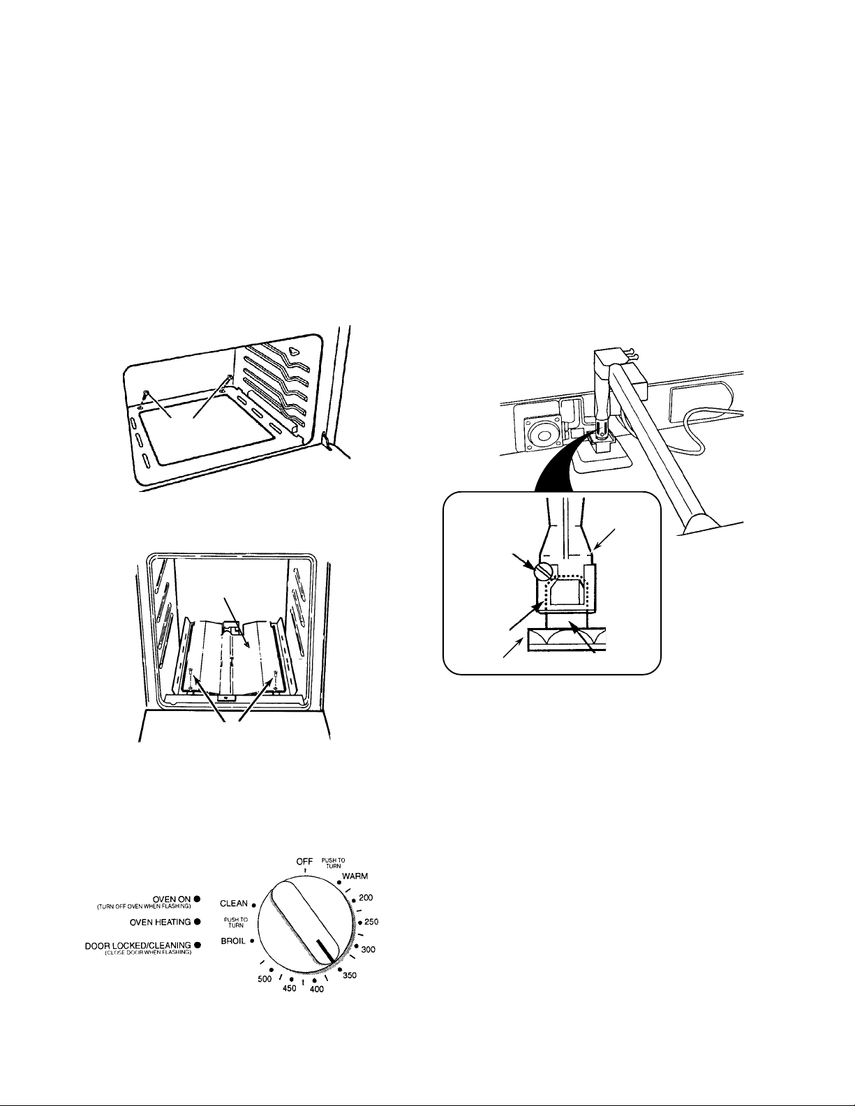
CHECKING THE OVEN BURNER OPERATION
THE BAKE BURNER
NOTE: The bake burner may be controlled by a
knob, or an electronic keypad. Refer to the oven
control that is used on the range you are testing.
Control Knob
1. Remove the oven racks.
2. Remove the two screws from the oven floor
and remove the floor.
screws
5. Check the flame coming from the burner bar.
If the flame is noisy, or is blowing away from
the bar, there is too much air during combustion. If the flame is soft and not high enough,
there is not enough air. If either of these
conditions occur, proceed to the next step.
6. With the burner lit, loosen the locking screw,
and adjust the venturi air shutter opening for
the best flame, then retighten the locking
screw.
3. Remove the screws from the heat shield over
the bake burner and remove the shield.
heat shield
screws
4. Push and turn the oven selector control knob
for a setting of 350˚F. The oven burner should
light in 50- to 60-seconds (the delay is due to
the time it takes for the gas valve to open and
the gas to flow to the burner).
bake burner
venturi
locking screw
air shutter
oven base
gas orifice
7. Turn the oven control knob to OFF. When the
oven cools, reinstall the heat shield, the oven
floor, and the oven racks.
1-16

Cooking Products Service Manual
Original July, 1996 4321891
© 1996 Whirlpool Corporation
Page 1-17
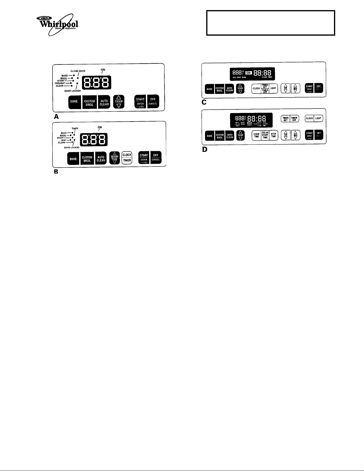
Electronic Oven Control 1
1. Press the BAKE keypad.
• The BAKE indicator will light.
• 350 will appear in the display.
• The START? indicator will begin to flash
after 5-seconds.
2. Press the START/ENTER keypad.
• The PREHEAT or HEAT and ON indicators will appear. NOTE: The PREHEAT
indicator light will not be displayed if the
oven temperature is over 170˚F.
• The display will show the automatic countdown time (10-minutes) needed to preheat the oven for the selected temperature.
• The oven burner should light in 50- to 60seconds (the delay is due to the time it
takes for the gas valve to open and the gas
to flow to the burner).
• After preheat, the PREHEAT indicator light
will go out (Control A only).
• A 1-second tone will sound.
• The countdown timer will change to 350.
3. Open the storage drawer and check the flame
coming from the burner bar. If the flame is
noisy, or is blowing away from the bar, there
is too much air during combustion. If the flame
is soft and not high enough, there is not
enough air. If either of these conditions occur,
refer to step 6 on page 1-16.
4. Press the OFF/CANCEL keypad.
Electronic Oven Control 2
1. Press the BAKE keypad.
• The BAKE indicator will light.
• 350 will appear in the display.
• The START? indicator will begin to flash
after 5-seconds (Control D only).
2. Press the START/ENTER keypad.
• PrE and 10:00 will appear.
• The HEAT and ON indicators will light.
• The oven burner should light in 50- to 60seconds (the delay is due to the time it
takes for the gas valve to open and the gas
to flow to the burner).
• The oven is preheated when the time in
the display counts down to 0:00.
• A 1-second tone will sound.
• PrE will change to 350.
3. Open the storage drawer and check the flame
coming from the burner bar. If the flame is
noisy, or is blowing away from the bar, there
is too much air during combustion. If the flame
is soft and not high enough, there is not
enough air. If either of these conditions occur,
refer to step 6 on page 1-16.
4. Press the OFF/CANCEL keypad.
1-17
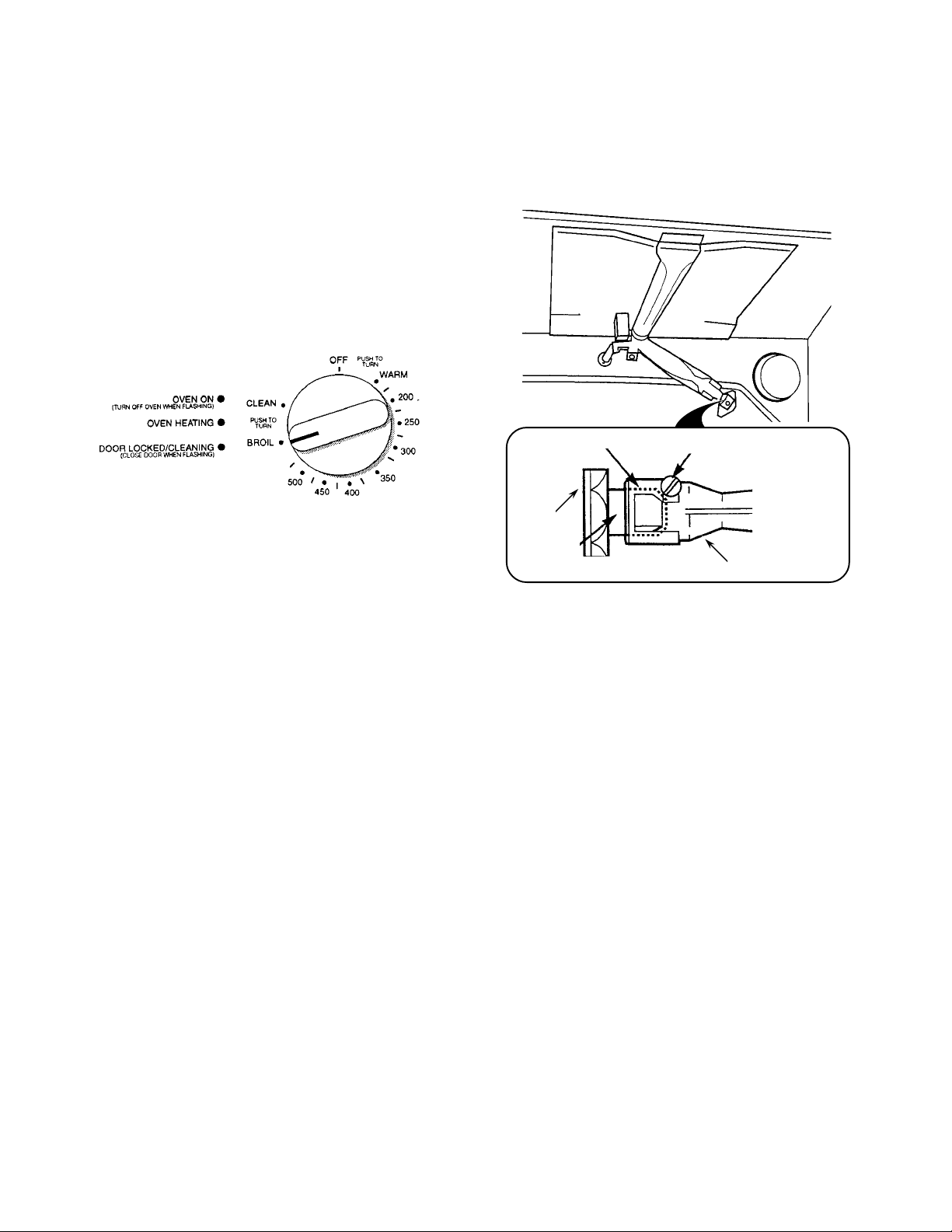
THE BROIL BURNER
NOTE: The broil burner may be controlled by a
knob, or an electronic keypad. Refer to the oven
control that is used on the range you are testing.
Control Knob
1. Push and turn the oven selector control knob
to BROIL. The broil burner should light in 50to 60-seconds (the delay is due to the time it
takes for the gas valve to open and the gas to
flow to the burner).
3. With the burner lit, loosen the locking screw,
and adjust the air shutter opening for the best
flame, then retighten the locking screw.
2. Check the flame coming from the broil burner
bar. If the flame is noisy, or is blowing away
from the bar, there is too much air during
combustion. If the flame is soft and not high
enough, there is not enough air. If either of
these conditions occur, proceed to the next
step.
air shutter
rear of
oven liner
gas orifice
locking screw
broil burner venturi
4. Turn the oven control knob to OFF.
1-18
Cooking Products Service Manual
Original July, 1996 4321891
© 1996 Whirlpool Corporation
Page 1-19
Electronic Oven Control 1
1. Press the CUSTOM BROIL keypad.
• 525 or HI will appear in the display.
• The BROIL indicator will light.
• The START? indicator will begin to flash
after 5-seconds.
2. Press the START/ENTER keypad.
• The HEAT (Control B only) and ON indicators will light.
• The broil burner should light in 50- to 60seconds (the delay is due to the time it
takes for the gas valve to open and the gas
to flow to the burner).
3. Open the storage drawer and check the flame
coming from the broil burner bar (use a mirror,
if necessary). If the flame is noisy, or is blowing away from the bar, there is too much air
during combustion. If the flame is soft and not
high enough, there is not enough air. If either
of these conditions occur, refer to step 3 on
page 1-18.
Electronic Oven Control 2
1. Press the CUSTOM BROIL keypad.
• HI will appear in the display.
• The BROIL indicator will light.
• The START? indicator will begin to flash
after 5-seconds.
2. Press the START/ENTER keypad.
• The HEAT and ON indicators will light.
• The broil burner should light in 50- to 60seconds (the delay is due to the time it
takes for the gas valve to open and the gas
to flow to the burner).
3. Open the storage drawer and check the flame
coming from the broil burner bar (use a mirror,
if necessary). If the flame is noisy, or is blowing away from the bar, there is too much air
during combustion. If the flame is soft and not
high enough, there is not enough air. If either
of these conditions occur, refer to step 3 on
page 1-18.
4. Press the OFF/CANCEL keypad.
4. Press the OFF/CANCEL keypad.
1-19
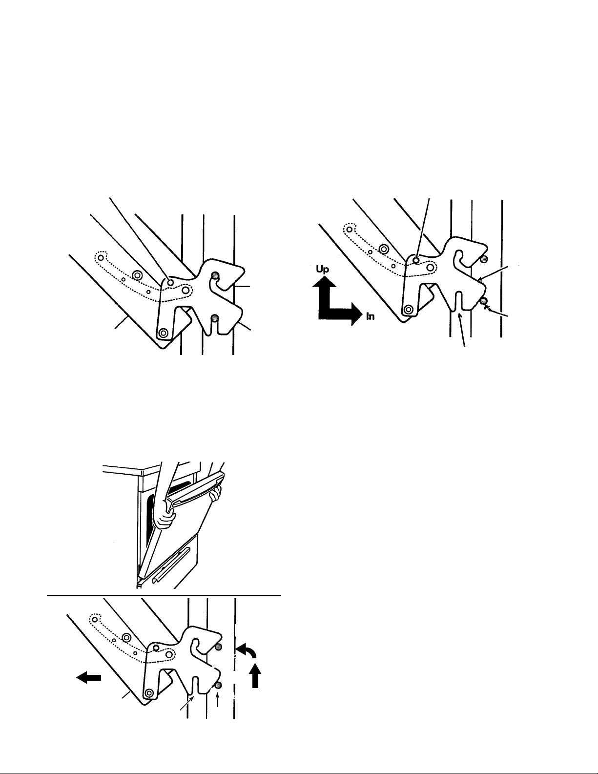
REMOVING/REINSTALLING THE OVEN DOOR
To remove the oven door:
1. Open the door approximately half way and
install the shipping pin (supplied with the
range), or a
hangers on each side of the door.
insert shipping pin or
allen wrench in this hole
oven door hinge
2. Close the oven door as far as the shipping
pins will allow.
3
/16" allen wrench, into the hinge
range
hanger
To reinstall the oven door:
1. Insert the hinge hangers into the front slots of
the range as far as they will go, then lift the
door while you push against it, and hook the
hinge slots in the pins.
remove shipping pin or
allen wrench from this hole
hinge
hanger
pin
slot
2. Remove the shipping pins and close the door.
3. Lift the door as far as possible so the slots in
the hinge hangers clear the pins, then rotate
the top toward you, and pull the hinges from
the slots in the front of the range.
2. ROTATE
3. PULL
oven door
1. LIFT
slot pin
1-20
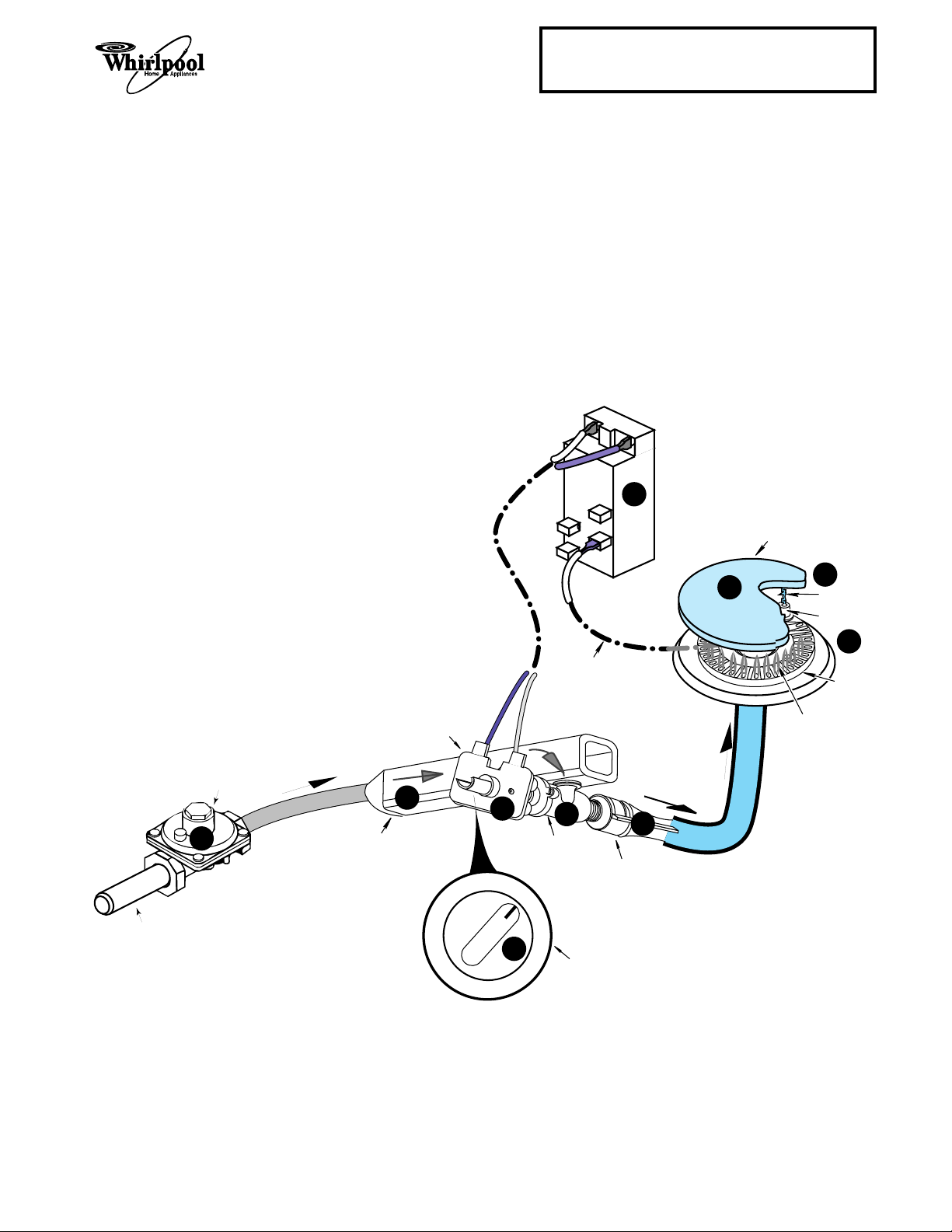
THEORY OF OPERATION
THE COOKTOP BURNERS
Refer to the illustration below while you read
this description.
When a surface burner control knob is turned
to the “lite” position, the gas valve r opens,
and gas from the pressure regulator s flows
into the manifold t, and through the open
valve. As gas passes through the valve and its
orifice, it is directed into the venturi u, where
it mixes with air to create the proper mixture
necessary for combustion.
At the same time, line voltage is applied through
the ignitor switch v to the ignitor module w,
which produces high-voltage pulses to all of
the burner ignitors x. The pulses cause a
spark y to occur between the burner ignitor
and the grounded burner cap z, which ignites
the gas and air mixture at the burner head, and
produces a flame.
Cooking Products Service Manual
Original July, 1996 4321891
© 1996 Whirlpool Corporation
IGNITOR
MODULE
7
Page 2-1
GAS INLET
PRESSURE
REGULATOR
3
GAS FLOW
IGNITOR SWITCH
GAS
MANIFOLD
4
120 VAC
LINE VOLTAGE
6
OFF
LITE
1
2
GAS VALVE
BURNER
CONTROL
HIGH VOLTAGE
PULSES
TO BURNER
IGNITOR
VENTURI
KNOB
GAS FLOW
5
BURNER CAP
10
9
SPARK
BURNER
IGNITOR
8
BURNER
BURNER FLAME
2-1
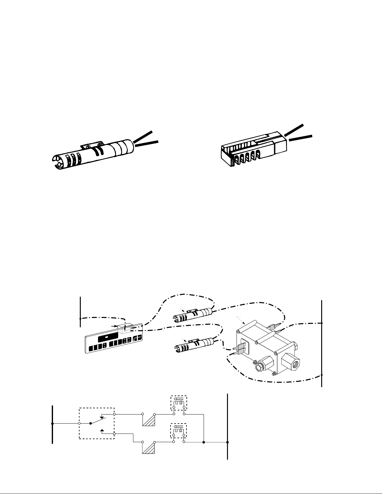
IGNITOR SYSTEM OVERVIEW
This gas range uses two Carborundum ignitors to provide a source for igniting gas from
the bake and broil burners. Norton ignitors
were previously used in the Whirlpool gas
ranges, and both of these ignitors operate the
same way. The only differences are in the
design (see the illustrations), and in the current ratings.
Carborundum Ignitor
2.5 - 3.0 Amps
IGNITOR SYSTEM OPERATION
The oven ignitor system in these Whirlpool
gas ranges has the following three main components, and is wired in a series-parallel circuit (see the illustration below):
1. An Electronic Oven Control (EOC).
2. Two Carborundum Ignitors (Bake &
Broil).
3. Dual Gas Safety Valve.
L1
BROIL IGNITOR
RELAY
CUSTOM
BAKE
O
F
HEAT BAKE BROIL LOCKED CLEAN TIMER
AUTO
CLEAN
BROIL
ON
TA
PF
DELAY
TIMER
CLOCK
SET
TIME
ELECTRONIC
OVEN CONTROL
(EOC)
S
N
E
MIN
HR
STOP
TIMER
OFF
OFF
RT
CANCEL
TER
5 SEC
BAKE IGNITOR
A Carborundum ignitor uses a round design,
and limits the operating current flow to between 2.5 and 3.0 amperes.
A Norton ignitor uses a rectangular design,
and limits the operating current flow to between 3.2 and 3.6 amperes.
Norton Ignitor
3.2 - 3.6 Amps
All of the self-clean gas ranges use these
components. When the EOC is set to the bake
or broil mode and a temperature is selected,
the relay on the EOC closes, and provides
power to the ignitor. With power applied, current flows through the ignitor circuit, and the
ignitor begins to heat and glow.
N
DUAL GAS
SAFETY VALVE
ELECTRONIC OVEN CONTROL
L1
RELAY
N
BROIL VALVE
BROIL IGNITOR
BAKE VALVE
BAKE IGNITOR
2-2
 Loading...