


W10123251
1
Ultra Low Nox
Gas Water Heater
with the Flame Lock™
Safety System
Installation
Instructions and
Use & Care Guide
Do not store or use gasoline or other
flammable vapors and liquids in the
vicinity of this or any other appliance.
WHAT TO DO IF YOU SMELL GAS
• Do not try to light any appliance.
• Do not touch any electrical switch;
do not use any phone in your
building.
• Immediately call your gas supplier
from a neighbor’s phone. Follow
the gas supplier’s instructions.
• If you cannot reach your gas
supplier, call the fire department.
Installation and service must be performed
by a qualified installer, service agency or
the gas supplier.
WARNING: If the information in these
instructions is not followed exactly, a fire
or explosion may result causing property
damage, personal injury or death.
INSTALLER:
• AFFIX THESE INSTRUCTIONS TO OR ADJACENT
TO THE WATER HEATER.
OWNER:
• RETAIN THESE INSTRUCTIONS AND WARRANTY
FOR FUTURE REFERENCE. RETAIN THE ORIGINAL
RECEIPT AS PROOF OF PURCHASE.
315422-000
W10123251
December 2008
Table of Contents ...................................................... 2
®
To obtain technical, warranty, or service assistance during or after
the installation of this water heater, visit our website at:
http://www.whirlpoolwaterheatersupport.com
or call toll free
1-877-817-6750
When calling for assistance, please have the following
information ready:
1. Model number
2. 7 digit product number
3. Serial number
4. Date of installation
5. Place of purchase
2
Important Instructions
• Do not use this appliance if any part has been under water. Immediately call a qualified service technician. Water
heaters subjected to flood conditions or any time the gas controls, main burner or pilot have been submerged in
water require replacement of the entire water heater.
• Hydrogen gas can be produced in a hot water system that has not been used for a long period of time (generally
two weeks or more). Hydrogen gas is extremely flammable and can ignite when exposed to a spark or flame. To
prevent the possibility of injury under these conditions, we recommend the hot water faucet be opened for several
minutes at the kitchen sink before using any electrical appliance which is connected to the hot water system. If
hydrogen is present, there will probably be an unusual sound such as air escaping through the faucet as water
begins to flow. Do not smoke or have any open flame near the faucet at the time it is open.
The California Safe Drinking Water and Toxic Enforcement Act requires the Governor of California to publish a list of
substances known to the State of California to cause cancer, birth defects, or other reproductive harm, and requires
businesses to warn of potential exposure to such substances.
WARNING: This product contains a chemical known to the State of California to cause cancer, birth defects, or other
reproductive harm.
This appliance can cause low-level exposure to some of the substances included in the Act.
Your safety and the safety of others are very important.
We have provided many important safety messages in this manual and on your appliance. Always read and obey all
safety messages.
This is the safety alert symbol.
This symbol alerts you to potential hazards that can kill or hurt you and others.
All safety messages will follow the safety alert symbol and either the word “DANGER” or
“WARNING.” These words mean:
You can be killed or seriously injured if you don’t
immediately follow instructions.
You can be killed or seriously injured if you don’t
follow instructions.
All safety messages will tell you what the potential hazard is, tell you how to reduce the chance of injury, and tell you
what can happen if the instructions are not followed.
Table Of Contents
Water Heater Safety . . . . . . . . . . . . . . . . . . . . . . . . . . . . . . . . . . . . . . 1-2
Installing Your Gas Water Heater . . . . . . . . . . . . . . . . . . . . . . . . . . . 3-16
Unpacking the Water Heater . . . . . . . . . . . . . . . . . . . . . . . . . . . . . . . 3
Location Requirements . . . . . . . . . . . . . . . . . . . . . . . . . . . . . . . . . 4-5
Gas Supply . . . . . . . . . . . . . . . . . . . . . . . . . . . . . . . . . . . . . . . . . . . . 6
Combustion Air Supply and Ventilation . . . . . . . . . . . . . . . . . . . . 7-11
Water System Piping . . . . . . . . . . . . . . . . . . . . . . . . . . . . . . . . . 12-15
Installation Checklist . . . . . . . . . . . . . . . . . . . . . . . . . . . . . . . . . . . . 16
Operating Your Water Heater . . . . . . . . . . . . . . . . . . . . . . . . . . . . . . 17-20
Lighting Instructions . . . . . . . . . . . . . . . . . . . . . . . . . . . . . . . . . . 17-18
Operational Conditions . . . . . . . . . . . . . . . . . . . . . . . . . . . . . . . . . . 20
Maintenance of Your Water Heater . . . . . . . . . . . . . . . . . . . . . . . . . 21-25
Troubleshooting Chart . . . . . . . . . . . . . . . . . . . . . . . . . . . . . . . . . . . 25-27
Repair Parts Illustration . . . . . . . . . . . . . . . . . . . . . . . . . . . . . . . . . . 28-29
PAGE
WATER HEATER SAFETY
3
INSTALLING YOUR GAS WATER HEATER
Important Information About
This Water Heater
This gas water heater was manufactured to voluntary
safety standards to reduce the likelihood of a flammable
vapor ignition incident. New technology used in meeting
these standards makes this product more sensitive to
installation errors or improper installation environments.
Please review the Installation Checklist found at the end of
the installation instructions section and make any required
installation upgrades or changes.
Consumer Information
This water heater is design-certified by CSA International
as a Category I, non-direct vented water heater which takes
its combustion air either from the installation area or from
air ducted to the unit from the outside.
This water heater must be installed according to all local
and state codes or, in the absence of local and state codes,
the “National Fuel Gas Code”, ANSI Z223.1(NFPA 54)-
latest edition. This is available from the following:
CSA America, Inc.
8501 East Pleasant Valley Road
Cleveland, OH 44131
National Fire Protection Association
1 Batterymarch Park
Quincy, MA 02269
Check your phone listings for the local authorities having
jurisdiction over your installation.
Consumer Responsibilities
This manual has been prepared to acquaint you with the
installation, operation, and maintenance of your gas water
heater and provide important safety information in these
areas.
Read all of the instructions thoroughly before attempting
the installation or operation of this water heater.
Do not discard this manual. You or future users of this
water heater will need it for future reference.
Service to the Flame Lock™Safety System should only be
performed by a qualified person.
Examples of a qualified person include: licensed plumbers,
authorized gas company personnel, and authorized
service personnel.
IMPORTANT: The manufacturer and seller of this water
heater will not be liable for any damages, injuries, or
deaths caused by failure to comply with the installation and
operating instructions outlined in this manual.
If you lack the necessary skills required to properly install
this water heater, or you have difficulty following the
instructions, you should not proceed but have a qualified
person perform the installation of this water heater.
Massachusetts code requires this water heater to be
Removing Packaging Materials
IMPORTANT: Do not remove any permanent instructions,
labels, or the data label from either the outside of the water
heater or on the inside of water heater panels.
• Remove exterior packaging and place installation
components aside.
• Inspect all parts for damage prior to installation and
start-up.
• Completely read all instructions before attempting to
assemble and install this product.
• After installation, dispose of/recycle all packaging
materials.
Unpacking the Water Heater
installed in accordance with Massachusetts Plumbing and
Fuel Gas Code 248 CMR Section 2.00 and 5.00.
A data plate identifying your water heater can be found next
to the gas control valve/thermostat. When referring to your
water heater, always have the information listed on the data
plate readily available.
Retain your original receipt as proof of purchase.
WARNING
Excessive Weight Hazard
Use two or more people to move and install
water heater.
Failure to do so can result in back or
other injury.
4
Location Requirements
The Flame Lock™Safety System is designed to reduce the
risk of flammable vapor-related fires. The patented system
protects your family by trapping the burning vapors within
the water heater combustion chamber through the special
flame-trap. The burning vapors literally “burn themselves
out” without escaping back into the room. In the event
of a flammable vapor incident, the Flame Lock™Safety
System disables the water heater by shutting off the gas
supply to the water heater’s burner and pilot, preventing
re-ignition of any remaining flammable vapors in the area.
This will not prevent a possible fire/explosion if the igniter
is depressed and flammable vapors have accumulated
in the combustion chamber with the pilot light off. If you
suspect a flammable vapor incident has occurred, do not
use this appliance. Do not attempt to light this appliance,
or depress the igniter button if you suspect flammable
vapors have accumulated inside or outside the appliance.
Immediately call a qualified person to inspect the
appliance. Water heaters subjected to a flammable vapors
incident will show a discoloration on the flame-trap and
require replacement of the entire water heater.
Do not use or store flammable products such as gasoline,
solvents, or adhesives in the same room or area near the
water heater. If such flammables must be used, all gas
burning appliances in the vicinity must be shut off and their
pilot lights extinguished. Open the doors and windows for
ventilation while flammable substances are in use.
If flammable liquids or vapors have spilled or leaked in
the area of the water heater, leave the area immediately
and call the fire department from a neighbor’s home. Do
not attempt to clean the spill until all ignition sources have
been extinguished.
Keep combustibles such as boxes, magazines, clothes,
etc. away from the water heater area.
Site Location
• Select a location near the center of the water piping
system. The water heater must be installed indoors and
in a vertical position on a level surface. Do not install in
bathrooms, bedrooms, or any occupied room normally
kept closed.
• Locate the water heater as close to the chimney or gas
vent as practical. Consider the vent system piping and
combustion air supply requirements when selecting the
water heater location. The venting system must be able
to run from the water heater to termination with minimal
length and elbows.
• Locate the water heater near the existing gas piping.
If installing a new gas line, locate the water heater to
minimize the pipe length and elbows.
NOTE: This water heater must be installed according to all
local and state codes or, in the absence of local and state
codes, the “National Fuel Gas Code”, ANSI Z223.1(NFPA
54)-latest edition.
Carbon Monoxide Poisoning Hazard
Do not install in a mobile home.
Doing so can result in death or
carbon monoxide poisoning.
WARNING
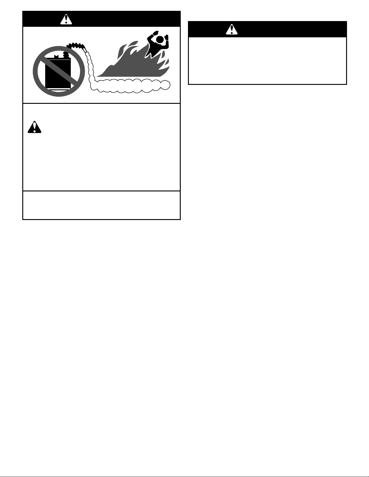
FIRE AND EXPLOSION HAZARD
Can result in serious injury or death
Do not store or use gasoline or other
flammable vapors and liquids in the
vicinity of this or any other appliance.
Storage of or use of gasoline or other
flammable vapors or liquids in the vicinity
of this or any other appliance can result in
serious injury or death.
Flammable Vapors
FLAMMABLES
Read and follow water heater warnings and
instructions.
WARNING
5
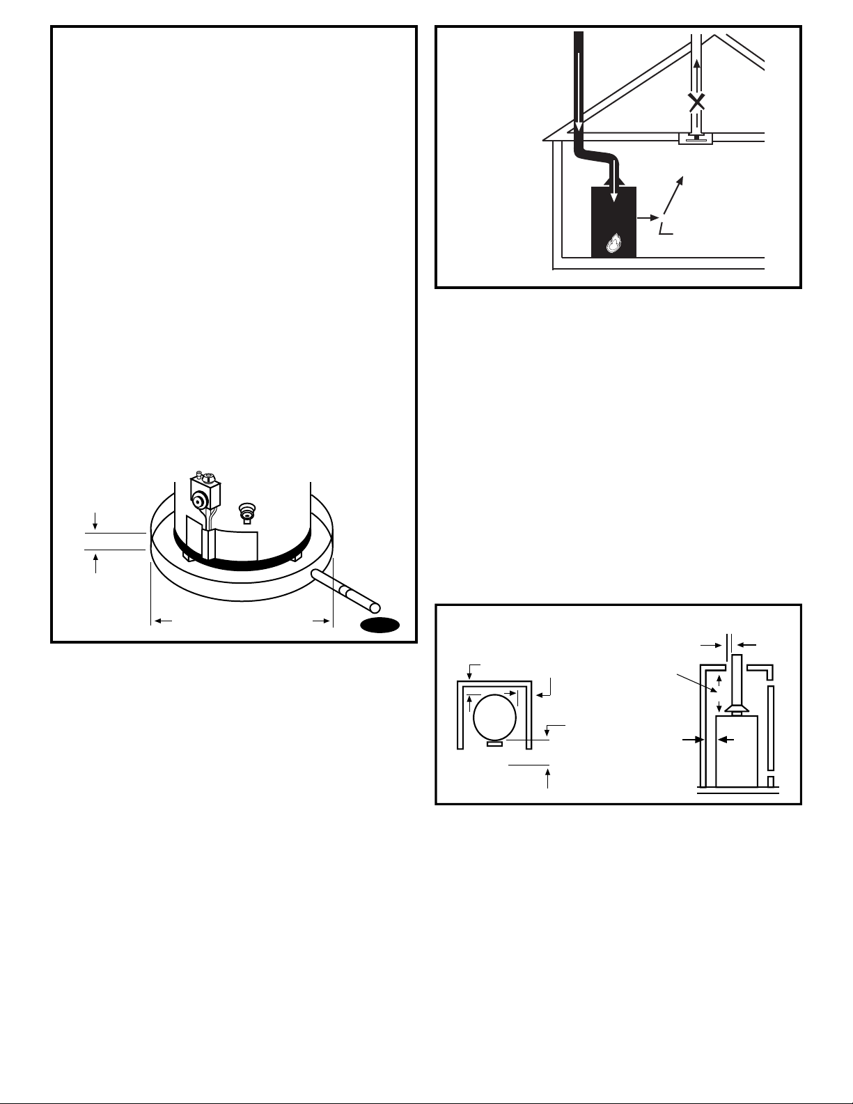
IMPORTANT: The water heater should be located in
an area where leakage of the tank or connections
will not result in damage to the area adjacent to the
water heater or to lower floors of the structure. Due
to the normal corrosive action of the water, the tank
will eventually leak after an extended period of time.
Also any external plumbing leak, including those from
improper installation, may cause early failure of the tank
due to corrosion if not repaired. If the owner/operator is
uncomfortable with making the repair a qualified person
should be contacted. A suitable metal drain pan should
be installed under the water heater as shown below,
to help protect the property from damage which may
occur from condensate formation or leaks in the piping
connections or tank. The pan must limit the water level
to a maximum depth of 1-3/4” and be two inches wider
than the heater and piped to an adequate drain. NOTE:
The pan must not restrict combustion air flow. Locate the
water heater near a suitable indoor drain. Outside drains
are subject to freezing temperatures which can obstruct
the drain line. The piping should be at least 3/4” ID and
pitched for proper drainage. Under no circumstance will
the manufacturer or seller of this water heater be held
liable for any water damage which is caused by your
failure to follow these instructions.
1 3/4” maximum
Pipe to
adequate
drain
At least 2” greater than the
diameter of the water heater.
• The water heater should be located in an area not
subject to freezing temperatures. Water heaters located
in unconditioned spaces (i.e., attics, basements,
etc.) may require insulation of the water piping and
drain piping to protect against freezing. The drain and
controls must be easily accessible for operation and
service. Maintain proper clearances as specified on the
data plate.
• Do not locate the water heater near an air-moving
device. The operation of air-moving devices such as
exhaust fans, ventilation systems, clothes dryers,
fireplaces, etc., can affect the proper operation of
the water heater. Special attention must be given to
conditions these devices may create. Flow reversal of
flue gases may cause an increase of carbon monoxide
inside of the dwelling.
• If the water heater is located in an area that is
subjected to lint, dirt, and oil, it may be necessary
to periodically clean the flame-trap and pilot (see
“External Inspection & Cleaning of the Flame-trap” and
“Cleaning the Pilot Assembly” section).
Figure 1
Air-moving
Devices
Reverse flow
of gases
Exhaust
Fan
Clearances and Accessibility
NOTE: Minimum clearances from combustible materials
are stated on the data plate adjacent to the gas control
valve/thermostat of the water heater.
The water heater is certified for installation on a
combustible floor.
• IMPORTANT: If installing over carpeting, the carpeting
must be protected by a metal or wood panel beneath
the water heater. The protective panel must extend
beyond the full width and depth of the water heater by
at least three inches (76.2mm) in any direction; or if in
an alcove or closet installation, the entire floor must be
covered by the panel.
• Figure 2 may be used as a reference guide to locate
the specific clearance locations. A minimum of 24
inches of front clearance should be provided for
inspection and service.
Back
Sides
Sides
Top
View
Top
to
ceiling
Vent
Front
24” minimum
for service
Figure 2
Minimum Clearance
Locations
State of California
NOTE: The water heater must be braced, anchored, or
strapped to avoid moving during an earthquake. Contact
local utilities for code requirements in your area or call
1-877-817-6750 and request instructions.
6
Gas Supply
Gas Requirements
IMPORTANT: Read the data plate to be sure the water
heater is made for the type of gas you will be using in
your home. This information will be found on the data
plate located near the gas control valve/thermostat. If the
information does not agree with the type of gas available,
do not install or light. Call your dealer.
NOTE: An odorant is added by the gas supplier to the gas
used by this water heater. This odorant may fade over an
extended period of time. Do not depend upon this odorant
as an indication of leaking gas.
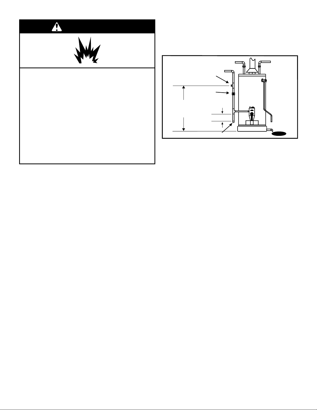
Gas Piping
The gas piping must be installed according to all local and
state codes or, in the absence of local and state codes, the
“National Fuel Gas Code”, ANSI Z223.1(NFPA 54)-latest
edition.
Table 1 on the following page is provided as a sizing
reference for commonly used gas pipe materials. Consult
the “National Fuel Gas Code” for the recommended gas
pipe size of other materials.
Refer to Figure 3
NOTE: When installing gas piping, apply approved pipe
joint compound.
1. Install a readily accessible manual shut-off valve in the
gas supply line as recommended by the local utility.
Know the location of this valve and how to turn off the
gas to this unit.
2. Install a drip leg (if not already incorporated as part of
the water heater) as shown. The drip leg must be no
less than three inches long for the accumulation of dirt,
foreign material, and water droplets.
3. Install a ground joint union between the gas control
valve/thermostat and the manual shut-off valve. This
is to allow easy removal of the gas control valve/
thermostat.
4. Turn the gas supply on and check for leaks. Test all
connections by brushing on an approved noncorrosive
leak-detection solution. Bubbles will show a leak.
Correct any leak found.
Figure 3
Gas Piping
Manual Gas
Shut-off Valve
Ground
Joint
Union
3” minimum
Check with
local utility
for minimum height
Drip leg
Gas Pressure
IMPORTANT: The gas supply pressure must not exceed
the maximum supply pressure as stated on the water
heater’s data plate. The minimum supply pressure is for
the purpose of input adjustment.
Gas Pressure Testing
IMPORTANT: This water heater and its gas connection
must be leak tested before placing the appliance in
operation.
• If the code requires the gas lines to be tested at a
pressure exceeding 14” W.C., the water heater and its
manual shut-off valve must be disconnected from the
gas supply piping system and the line capped.
• If the gas lines are to be tested at a pressure less than
14” W.C., the water heater must be isolated from the
gas supply piping system by closing its manual shut-off
valve.
U.L. recognized fuel gas and carbon monoxide (CO)
detectors are recommended in all applications and should
be installed using the manufacturer’s instructions and local
codes, rules, or regulations.
NOTE: Air may be present in the gas lines and could
prevent the pilot from lighting on initial start-up. The gas
lines should be purged of air by a qualified person after
installation of the gas piping system.
Explosion Hazard
Use a new CSA approved gas supply line.
Install a shut-off valve.
Do not connect a natural gas water heater to
an L.P. gas supply.
Do not connect an L.P. gas water heater to a
natural gas supply.
Failure to follow these instructions can
result in death, explosion, or
carbon monoxide poisoning.
WARNING
7
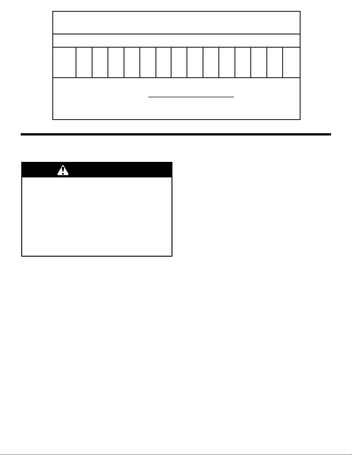
Nominal Iron Pipe Length of Pipe, Feet
Size, in.
1/2
3/4
1
1-1/4
1-1/2
132
278
520
1050
1600
92
190
350
730
1100
73
152
285
590
890
63
130
245
500
760
56
11 5
215
440
670
50
105
195
400
610
46
96
180
370
560
43
90
170
350
530
40
84
160
320
490
38
79
150
305
460
34
72
130
275
410
31
64
120
250
380
28
59
11 0
225
350
26
55
100
210
320
10 20 30 40 50 60 70 80 90 100 125 150 175 200
Table 1
Natural Gas Pipe Capacity Table (Cu. Ft./Hr.)
Capacity of gas pipe of different diameters and lengths in cu. ft. per hr. with pressure drop of 0.3 in. and specific gravity
of 0.60 (natural gas).
After the length of pipe has been determined, select the pipe size which will provide the minimum cubic feet per hour
required for the gas input rating of the water heater. By formula:
Gas Input of Water Heater (BTU/HR)
Heating Value of Gas (BTU/FT³)
The gas input of the water heater is marked on the water heater data plate. The heating value of the gas (BTU/FT )
may be determined by consulting the local natural gas utility.
3
Cu. Ft. Per Hr. Required=
Additional tables are available in the latest edition of the "National Fuel Gas Code", ANSI Z223.1.
Combustion Air Supply and
Ventilation
IMPORTANT: Air for combustion and ventilation must not
come from a corrosive atmosphere. Any failure due to
corrosive elements in the atmosphere is excluded from
warranty coverage.
The following types of installation (not limited to the
following) will require outdoor air for combustion due to
chemical exposure and may reduce but not eliminate the
presence of corrosive chemicals in the air:
• beauty shops
• photo processing labs
• buildings with indoor pools
• water heaters installed in laundry, hobby, or craft
rooms
• water heaters installed near chemical storage areas
Combustion air must be free of acid-forming chemicals
such as sulfur, fluorine, and chlorine. These elements are
found in aerosol sprays, detergents, bleaches, cleaning
solvents, air fresheners, paint, and varnish removers,
refrigerants, and many other commercial and household
products. When burned, vapors from these products form
highly corrosive acid compounds. These products should
not be stored or used near the water heater or air inlet.
Combustion and ventilation air requirements are
determined by the location of the water heater. The water
heater may be located in either an open (unconfined) area
or in a confined area or small enclosure such as a closet
or small room. Confined spaces are areas with less than
50 cubic feet for each 1,000 BTUH of the total input for all
gas using appliances.
Carbon Monoxide Warning
Follow all the local and state codes or, in
the absence of local and state codes, the
“National Fuel Gas Code”, ANSI Z223.1
(NFPA 54)- latest edition to properly install
vent system.
Failure to do so can result in death,
explosion, or carbon monoxide poisoning.
WARNING
8
Unconfined Space
A water heater in an unconfined space uses indoor air for
combustion and requires at least 50 cubic feet for each
1,000 BTUH of the total input for all gas appliances. The
table below shows a few examples of the minimum square
footage (area) required for various BTUH inputs.
30,000
45,000
60,000
75,000
90,000
105,000
120,000
135,000
188
281
375
469
563
657
750
844
9 x 21
14 x 20
15 x 25
15 x 31
20 x 28
20 x 33
25 x 30
28 x 30
Typical Room
with 8' Ceiling
Minimum Square
Feet with
8' Ceiling
BTUH
Input
Table 2
IMPORTANT:
• The area must be open and be able to provide the
proper air requirements to the water heater. Areas that
are being used for storage or contain large objects may
not be suitable for water heater installation.
• Water heaters installed in open spaces in buildings with
unusually tight construction may still require outdoor
air to function properly. In this situation, outside air
openings should be sized the same as for a confined
space.
• Modern home construction usually requires supplying
outside air into the water heater area.
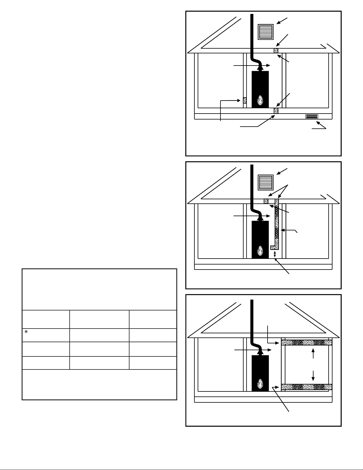
Confined Space
For the correct and proper operation of this water heater,
ample air must be supplied for the combustion, ventilation,
and dilution of flue gases. Small enclosures and confined
areas must have two permanent openings so that sufficient
fresh air can be drawn from outside of the enclosure. One
opening shall be within 12 inches of the top and one within
12 inches of the bottom of the enclosure as shown in
Figure 4.
The size of each opening (free area) is determined by the
total BTUH input of all gas utilization equipment (i.e., water
heaters, furnaces, clothes dryers, etc.) and the method by
which the air is provided. The BTUH input can be found on
the water heater data plate. Additional air can be provided
by two methods:
1. All air from inside the building.
2. All air from outdoors.
Figure 4
Opening Locations-
Confined Spaces
12” maximum
Permanent
openings to
the outside or
additional
rooms within
the building
Closet
or
other
confined
space
12” maximum
All Air from Inside the Building
When additional air is to be provided to the confined area
from additional room(s) within the building, the total volume
of the room(s) must be of sufficient size to properly provide
the necessary amount of fresh air to the water heater
and other gas utilization equipment in the area. If you are
unsure that the structure meets this requirement, contact
your local gas utility company or other qualified agency for
a safety inspection.
Each of the two openings shall have a minimum free area
of 1 square inch per 1,000 BTUH of the total input rating of
all gas utilization equipment in the confined area, but not
less than 100 square inches. (Figure 5.)
Confined
Space
Figure 5
All Air from Inside Building
Confined Space Installation
Permanent
Openings
1 square
inch/1000
BTUH
(minimum
100 sq. In.
each)
9
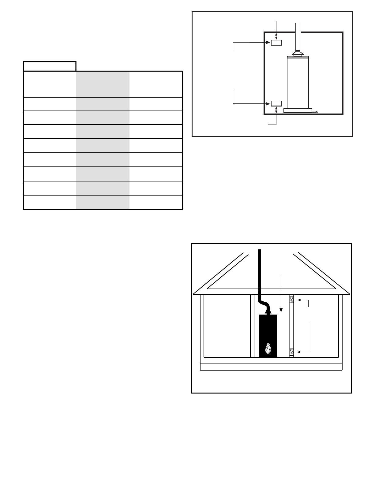
All Air from Outdoors
Outdoor fresh air can be provided to a confined area either
directly or by the use of vertical and horizontal ducts. The
fresh air can be taken from the outdoors or from crawl or
attic spaces that freely communicate with the outdoors.
Attic or crawl spaces cannot be closed and must be
properly ventilated to the outside.
Ductwork must be of the same cross-sectional area as
the free area of the opening to which they connect. The
minimum dimension of rectangular air ducts cannot be less
than three inches.
The size of each of the two openings is determined by the
method in which the air is to be provided. Refer to Table
3 to calculate the minimum free area for each opening.
Figures 6, 7, and 8 are typical examples of each method.
Louvers and Grilles
In calculating free area for ventilation and combustion
air supply openings, consideration must be given to the
blocking effect of protection louvers, grilles, and screens.
These devices can reduce airflow, which in turn may
require larger openings to achieve the required minimum
free area. Screens must not be smaller than 1/4” mesh. If
the free area through a particular design of louver or grille
is known, it should be used in calculating the specified
free area of the opening. If the design and free area are
not known, it can be assumed that most wood louvers will
allow 20 - 25% of free area while metal louvers and grilles
will allow 60 - 75% of free area.
Louvers and grilles must be locked open or interconnected
with the equipment so that they are opened automatically
during equipment operation.
Keep louvers and grilles clean and free of debris or other
obstructions.
Direct to
outdoors
Vertical ducts
Horizontal ducts
Figure 6
Figure 7
Figure 8
Table 3
Minimum Free Area of Permanent Openings for Ventilation and
Combustion Air Supply - All Air from Outdoors Only.
Based on the total BTUH input rating for all gas utilizing equipment
within the confined space.
Opening
Source
1 Square inch per 4000
BTUH
1 Square inch per 4000
BTUH
1 Square inch per 2000
BTUH
Minimum Free Area
Per Opening
(sq. in.)
Reference
Drawing
Example: A water heater with an input rate of 50,000 BTUH using
horizontal ducts would require each opening to have a minimum
free area of 25 square inches.
Minimum free area = 50,000 BTUH x 1 sq. in. / 2000 BTUH = 25
Sq. Inches.
* These openings connect directly with the outdoors
through a ventilated attic, a ventilated crawl space, or
through an outside wall.
Consult the local codes of your area for specific ventilation
and combustion air requirements.
Confined
Space
Figure 8
All Air from Outdoors
Using Horizontal Ducts
Outdoor
Air Ducts
Outlet
Inlet
1 sq. inch
per
2000 BTUH
1 sq. inch per
4000 BTUH
Confined
Space
Figure 6
All Air from Outdoors; Inlet Air from Ventilated
Crawl Space/Outlet Air to Ventilated Attic
Inlet air
from the
crawl
space
Install above
insulation
Gable vent
to outdoors
Outlet
air to attic
1 Sq. inch per
4000 BTUH
Alternate
Air Inlet
Open
Foundation
Vent
Confined
Space
Figure 7
All Air from Outdoors
Through Ventilated Attic
Inlet air duct
1 sq. inch per
4000 BTUH
Install above
insulation
Gable vent
to outdoors
Outlet air
to attic
1 Sq. inch per
4000 BTUH
12” maximum
1sq.Inch
per
2000 BTUH
10
Vent Pipe System
This water heater uses a non-direct, single-pipe vent
system to remove exhaust gases created by the burning of
fossil fuels. Air for combustion is taken from the immediate
water heater location or is ducted in from the outside (see
“Combustion Air Supply and Ventilation” section).
This water heater must be properly vented for the removal
of exhaust gases to the outside atmosphere. Correct
installation of the vent pipe system is mandatory for the
proper and efficient operation of this water heater and is an
important factor in the life of the unit.
The vent pipe must be installed according to all local and
state codes or, in the absence of local and state codes, the
“National Fuel Gas Code”, ANSI Z223.1(NFPA 54)-latest
edition. The vent pipe installation must not be obstructed
so as to prevent the removal of exhaust gases to the
outside atmosphere.
IMPORTANT: The use of vent dampers is not
recommended by the manufacturer of this water heater.
Although some vent dampers are certified by CSA
International, this certification applies to the vent damper
device only and does not mean they are certified for use
on this water heater.
U.L. recognized fuel gas and carbon monoxide (CO)
detectors are recommended in all applications and should
be installed using the manufacturer’s instructions and local
codes, rules, or regulations.
IMPORTANT: If you lack the necessary skills required
to properly install this venting system, you should not
proceed, but get help from a qualified person.
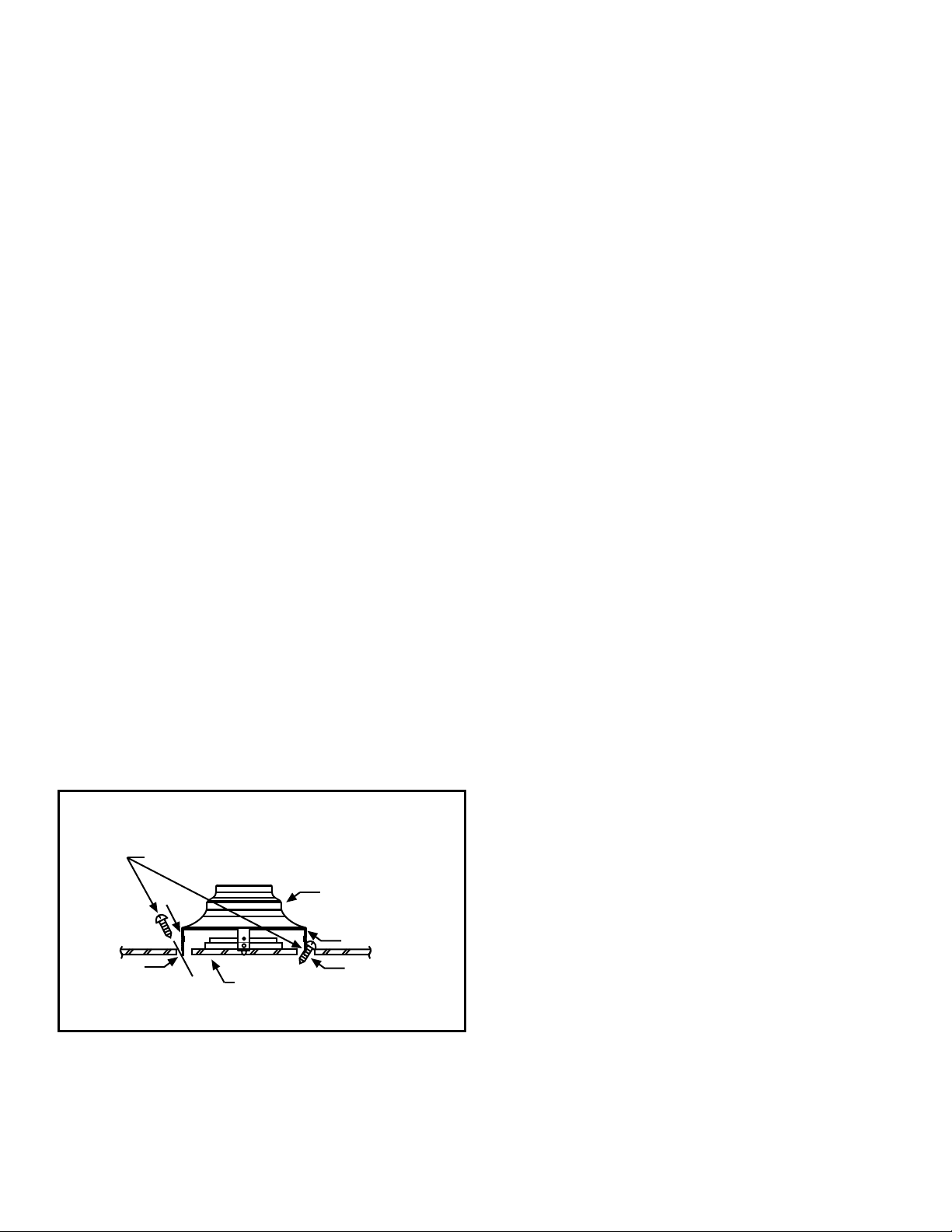
Draft hood Installation
Align the legs of the draft hood with the slots provided.
Insert the legs and secure the draft hood to the water
heater’s top with the four screws provided as shown in
Figure 9. Do not alter the draft hood in any way. If you are
replacing an existing water heater, be sure to use the new
draft hood supplied with the water heater.
Vent Pipe Size
It is important that you follow the guidelines in these
instructions for sizing a vent pipe system. If a transition to
a larger vent size is required, the vent transition connection
must be made at the draft hood outlet.
Vent Connectors
1. Type B, Double Wall, U.L. Listed Vent Pipe.
2. Single Wall Vent Pipe.
Maintain the manufacturer’s specified minimum clearance
from combustible materials when using type B double wall
vent pipe.
Vent connectors made of type B, double wall vent pipe
material may pass through walls or partitions constructed
of combustible material if the minimum listed clearance is
maintained.
Maintain a six inch minimum clearance from all
combustible materials when using single wall vent pipe.
IMPORTANT: Single wall vent pipe cannot be used for
water heaters located in attics and may not pass through
attic spaces, crawl spaces or any confined or inaccessible
location. A single wall metal vent connector cannot pass
through any interior wall.
When installing a vent connector, please note the following:
• Install the vent connector avoiding unnecessary bends,
which create resistance to the flow of vent gases.
• Install without dips or sags with an upward slope of at
least 1/4-inch per foot.
• Joints must be fastened by sheet metal screws or other
approved means. It must be supported to maintain
clearances and prevent separation of joints and
damage.
• The length of the vent connector cannot exceed 75% of
the vertical vent height.
• The vent connector must be accessible for cleaning,
inspection, and replacement.
• Vent connectors cannot pass through any ceiling, floor,
firewall, or fire partition.
IMPORTANT: Existing vent systems must be inspected for
obstructions, corrosion, and proper installation.
Figure 9
Draft hood Inst allation
Sheet Metal Screws (four provided)
Draft hood
Jacket top
Install the draft hood with
the four screws provided.
Slot
Slot
Legs
Legs
 Loading...