

Whirlpool KWVU205YBA2 Installation Instructions And Use & Care Manual
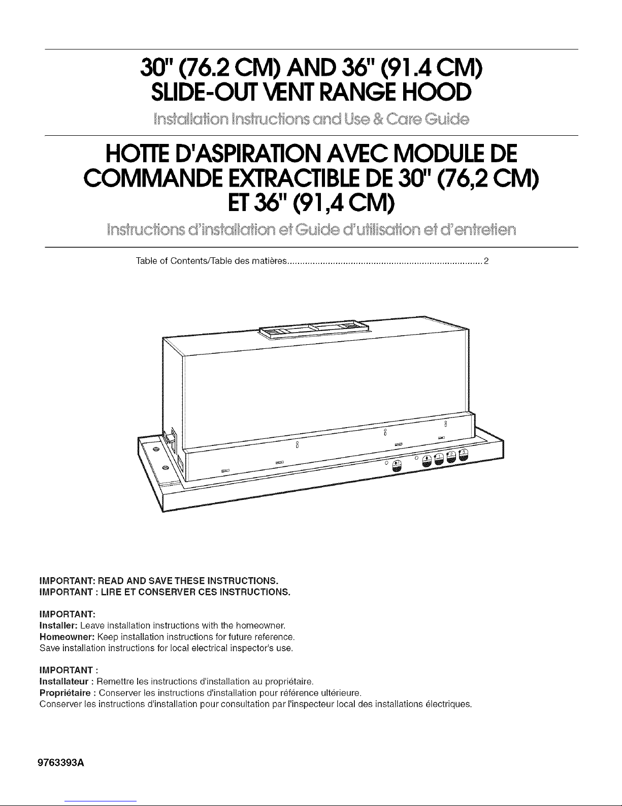
30"(76.2 CM) AND 36"(91.4 CM)
SLIDE-OUTVENTRANGEHOOD
HOTTED'ASPIRATIONAVEC MODULEDE
COMMANDE EXTRACTIBLEDE30" (76,2 CM)
ET36"(91,4 CM)
Table of Contents/Table des matieres ............................................................................. 2
I
IMPORTANT: READ AND SAVE THESE INSTRUCTIONS.
IMPORTANT : LIRE ET CONSERVER CES INSTRUCTIONS.
IMPORTANT:
Installer: Leave installation instructions with the homeowner.
Homeowner: Keep installation instructions for future reference.
Save installation instructions for local electrical inspector's use.
IMPORTANT :
Installateur : Remettre les instructions d'installation au proprk£taire.
Propri_taire : Conserver les instructions d'installation pour r_£f@enceulterieure.
Conserver les instructions d'installation pour consultation par I'inspecteur local des installations _£1ectriques.
9763393A
TABLEOF CONTENTS
TABLEDESMATIERES
RANGE HOOD SAFETY ................................................................. 3
INSTALLATION REQUIREMENTS ................................................ 4
Tools and Parts ............................................................................ 4
Location Requirements ................................................................ 4
Venting Requirements .................................................................. 5
Electrical Requirements ............................................................... 7
INSTALLATION INSTRUCTIONS .................................................. 7
Prepare Location .......................................................................... 7
Install Range Hood ..................................................................... 10
Electrical Connection ................................................................. 10
Connect the Vent System .......................................................... 11
Optional Front Trim Kits ............................................................. 12
RANGE HOOD USE ...................................................................... 12
KWVU Model Series ................................................................... 12
GZ and IH Model Series ............................................................ 13
RANGE HOOD CARE ................................................................... 13
Cleaning ...................................................................................... 13
Replacing the Bulb ..................................................................... 13
WIRING DIAGRAMS ..................................................................... 14
ASSISTANCE OR SERVICE ......................................................... 16
In the U.S.A ................................................................................ 16
In Canada ................................................................................... 16
WAR RAN TY .................................................................................. 17
WAR RAN TY .................................................................................. 18
SECURITE DE LA HOTTE D'ASPIRATION ................................ 19
EXIGENCES D'INSTALLATION ................................................... 21
Outillage et pieces ...................................................................... 21
Exigences d'emplacement ......................................................... 21
Exigences concernant I'evacuation ........................................... 22
Specifications electriques .......................................................... 24
INSTRUCTIONS D'INSTALLATION ............................................. 25
Preparation de I'emplacement ................................................... 25
Installation de la hotte de cuisiniere ........................................... 28
Raccordement electrique ........................................................... 29
Raccordement du circuit d'evacuation ...................................... 29
Ensembles de garniture (option) ................................................ 30
UTILISATION DE LA HOTTE DE CUlSINIERE ........................... 30
Modeles Series KWVU .............................................................. 30
Modeles Series GZ et IH ............................................................ 31
ENTRETIEN DE LA HOTTE DE CUlSlNII_RE ............................. 31
Nettoyage ................................................................................... 31
Remplacement de la lampe ....................................................... 31
SCHEMA DE CABLAGE ............................................................... 32
ASSISTANCE OU SERVICE ......................................................... 33
GARANTIE .................................................................................... 34
GARANTI E ..................................................................................... 35
RANGE HOOD SAFETY
Your safety and the safety of others are very important.
We have provided many important safety messages in this manual and on your appliance. Always read and obey all safety
messages.
This is the safety alert symbol.
This symbol alerts you to potential hazards that can kill or hurt you and others.
All safety messages will follow the safety alert symbol and either the word "DANGER" or "WARNING."
These words mean:
You can be killed or seriously injured if you don't immediately
follow instructions.
You can be killed or seriously injured if you don't follow
instructions.
All safety messages will tell you what the potential hazard is, tell you how to reduce the chance of injury, and tell you what can
happen if the instructions are not followed.
IMPORTANT SAFETY INSTRUCTIONS
WARNING: TO REDUCE THE RISK OF FIRE, ELECTRIC
SHOCK, OR INJURY TO PERSONS, OBSERVE THE
FOLLOWING:
[] Use this unit only in the manner intended by the
manufacturer. If you have questions, contact the
manufacturer.
[] Before servicing or cleaning the unit, switch the power off at
the service panel disconnecting means to prevent power
from being switched on accidentally. When the service
disconnecting means cannot be locked, securely fasten a
prominent warning device, such as a tag, to the service
panel.
[] Installation work and electrical wiring must be done by
qualified person(s) in accordance with all applicable codes
& standards, including fire-rated construction.
[] Sufficient air is needed for proper combustion and
exhausting of gases through the flue (chimney) of fuel
burning equipment to prevent backdrafting. Follow the
heating equipment manufacturer's guideline and safety
standards such as those published by the National Fire
Protection Association (NFPA), the American Society for
Heating, Refrigeration and Air Conditioning Engineers
(ASHRAE), and the local code authorities.
[] When cutting or drilling into wall or ceiling; do not damage
electrical wiring and other utilities.
[] Ducted systems must always be vented outdoors.
CAUTION: For general ventilating use only. Do not use
to exhaust hazardous or explosive materials and vapors.
CAUTION: To reduce risk of fire and to properly exhaust
air, be sure to duct air outside - do not vent exhaust air into
spaces within walls ceilings, attics, crawl spaces, or
garages.
WARNING: TO REDUCE THE RISK OF FIRE, USE ONLY
METAL DUCTWORK.
WARNING: TO REDUCE THE RISK OF A RANGE TOP
GREASE FIRE:
[] Never leave the surface units unattended at high settings.
Boilovers cause smoking and greasy spillovers that may
ignite. Heat oils slowly on low or medium settings.
[] Always turn hood ON when cooking at high heat or when
flambeing food (i.e. Crepes Suzette, Cherries Jubilee,
Peppercorn Beef Flambe).
[] Clean ventilating fans frequently. Grease should not be
allowed to accumulate on fan or filter.
[] Use proper pan size. Always use cookware appropriate for
the size of the surface element.
WARNING: TO REDUCE THE RISK OF INJURY TO
PERSONS IN THE EVENT OF A RANGE TOP GREASE
FIRE, OBSERVE THE FOLLOWING: _
[] SMOTHER FLAMES with a close fitting lid, cookie sheet, or
other metal tray, then turn off the gas burner or electric
element. BE CAREFUL TO PREVENT BURNS. If the
flames do not go out immediately, EVACUATE AND CALL
THE FIRE DEPARTMENT.
[] NEVER PICK UP A FLAMING PAN - you may be burned.
[] DO NOT USE WATER, including wet dishcloths or towels -
a violent steam explosion will result.
[] Use an extinguisher ONLY if:
- You know you have a class ABC extinguisher, and you
already know how to operate it.
- The fire is small and contained in the area where it
started.
- The fire department is being called.
- You can fight the fire with your back to an exit.
%ased on "Kitchen Fire Safety Tips" published by NFPA.
SAVE THESE INSTRUCTIONS
INSTALLATIONREQUIREMENTS
Gather the required tools and parts before starting installation.
Read and follow the instructions provided with any tools listed
here.
Tools needed
• Level
• Drill
• 11/4"drill bit
• %" (8 mm) nut driver or ratchet
• Pencil
• Pliers
• Wire stripper or utility knife
• Tape measure or ruler
• Caulking gun and weatherproof caulking compound
• Phillips screwdriver
• Flat-blade screwdriver
• Saber or keyhole saw
• Vent clamps
• Metal snips
Parts supplied
Check that all parts are included.
• Literature package
• 2 screws
• Damper
• Plastic cover (used for customized front panel)
• Hardware package
Parts needed
• Two 1/2"(12.7 mm) UL listed or CSA approved conduit
connectors
• Wall cap
• Metal vent system
• Power supply cable
Optional parts needed:
• Wood filler strips for cabinets with recessed bottoms. Length
and thickness determined by recess dimensions. See
"Prepare Location" section.
• Two, 1" x 1" x 5" (25.4 x 25.4 x 127 mm) wood pieces for
cabinet floor. See "Prepare Location" section.
• Four, 11/4"(31.8 mm) wood screws
IMPORTANT: Observe all governing codes and ordinances.
• Have a qualified technician install the range hood. It is the
installer's responsibility to comply with installation clearances
specified on the model/serial rating plate. The model/serial
rating plate is located behind the left filter on the rear wall of
the vent hood.
• Range hood location should be away from strong draft areas,
such as windows, doors, and strong heating vents.
Cabinet opening dimensions that are shown must be used.
Given dimensions provide minimum clearance. Consult your
cooktop/range manufacturer installation instructions before
making any cutouts.
• Grounded electrical outlet is required. See "Electrical
Requirements" section.
• The hood is factory set for vented installations through the
roof or wall.
For non-vented installations, Recirculation Kit Part
No. 883140 is available from your dealer or an authorized
parts distributor.
• All openings in ceiling and wall where range hood will be
installed must be sealed.
For Mobile Home Installations
The installation of this range hood must conform to the
Manufactured Home Construction Safety Standards, Title 24
CFR, Part 328 (formerly the Federal Standard for Mobile Home
Construction and Safety, title 24, HUD, Part 280) or when such
standard is not applicable, the standard for Manufactured Home
Installation 1982 (Manufactured Home Sites, Communities and
Setups) ANSI A225.1/NFPA 501A*, or latest edition, or with local
codes.
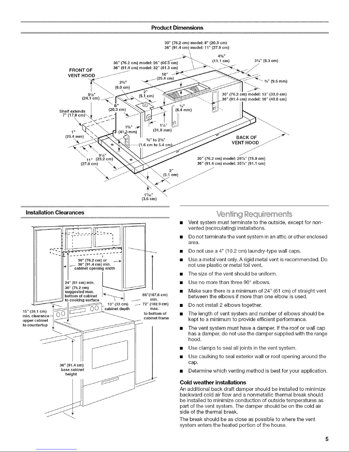
FRONT OF
VENT HOOD
Product Dimensions
30" (75.2 cm) model: 8" (20.3 cm)
36" (01.4 cm) model: 11" (27.9 cm)
30" (76.2 cm) model: 25" (66_.0 cm)
35" (91.4 cm) modem: 32" (81.3 cm)
10"
%" (9.5 ram)
Shelf extends (20.3 cm)
7" (17.,0cm)\ / /
\
1" nm)
Installation Clearances
30" (76.2 cm) or
36" (91.4 cm) min.
cabinet opening width
30" (76.2 cm)
24" (61 cm) rain.
suggested max.
bottom of cabinet
to cooking surface
15" (38.1 cm)
min. clearance-
upper cabinet _
to countertop __
36" (91.4era)
base cabinet
height
91/2 ''
(24.1 cm)
91/8 "
11" (23.2 cm)
(27.9 era) \
\
..... I.....
/
13" (33 cm)
cabinet depth
1%"
/ rain.
/
(31.8 mm)
%" to 2%"
1.6 cm
66"(167.8 cm)
72" (182.9 cm)
max.
to bottom of
cabinet frame
30" (75.2 cm) model: 13" (33.0 cm)
136" (91.4 cm) model: 15" (40.6 cm)
BACK OF
VENT HOOD
J
J
30" (76.2 era) model: 297/8 '' (75.9 cm)
36" (91.4cm) model: 357/8'' (91.1 cm)
• Vent system must terminate to the outside, except for non-
vented (recirculating) installations,
• Do not terminate the vent system in an attic or other enclosed
area,
• Do not use a 4" (10.2 cm) laundry-type wall caps,
• Use a metal vent only, A rigid metal vent is recommended, Do
not use plastic or metal foil vent.
• The size of the vent should be uniform.
• Use no more than three 90° elbows.
• Make sure there is a minimum of 24" (61 cm) of straight vent
between the elbows if more than one elbow is used,
• Do not install 2 elbows together.
• The length of vent system and number of elbows should be
kept to a minimum to provide efficient performance,
• The vent system must have a damper. If the roof or wall cap
has adamper, do not use the damper supplied with the range
hood.
• Use clamps to seal all joints in the vent system.
• Use caulking to seal exterior wall or roof opening around the
cap.
• Determine which venting method is best for your application.
Cold weather installations
An additional back draft damper should be installed to minimize
backward cold air flow and a nonmetallic thermal break should
be installed to minimize conduction of outside temperatures as
part of the vent system. The damper should be on the cold air
side of the thermal break.
The break should be as close as possible to where the vent
system enters the heated portion of the house.
Makeup air
Local building codes may require the use of makeup air systems
when using ventilation systems with greater than specified CFM
of air movement, The specified CFM varies from locale to locale.
Consult your HVAC professional for specific requirements in your
area.
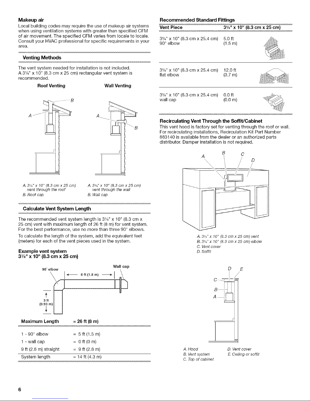
Venting Methods
Recommended Standard Fittings
Vent Piece 31A'' x 10" (8.3 cm x 25 cm)
31/4'' x 10" (8.3 cm x 25.4 cm) 5.0 ft
90° elbow (1.5 m)
The vent system needed for installation is not included.
A 31/4'' x 10" (8,3 cm x 25 cm) rectangular vent system is
recommended.
Roof Venting Wall Venting
A. 3,/4" x10" (8.3 cm x 25 cm)
vent through the roof
B. Roof cap
A. 31/Ix 10" (8.3 cm x 25 cm)
vent through the wall
B. Wall cap
Calculate Vent System Length
3V4"x 10" (8.3 cm x 25.4 cm) 12.0 ft
flat elbow (3.7 m)
31/4'' x 10" (8.3 cm x 25,4 cm) 0.0 ft
wall cap (0.0 m)
Recirculating Vent Through the Soffit/Cabinet
This vent hood is factory set for venting through the roof or wall.
For recirculating installations, Recirculation Kit Part Number
883140 is available from the dealer or an authorized parts
distributor. Damper installation is not required.
The recommended vent system length is 3_/4'' x 10" (8.3 cm x
25 cm) vent with maximum length of 26 ft (8 m) for vent system,
For the best performance, use no more than three 90+ elbows.
To calculate the length of the system, add the equivalent feet
(meters) for each of the vent pieces used in the system,
Example vent system
3V4"x 10" (8.3 cm x 25 cm)
90 + elbow Wal cap
I
(o.@t
Maximum Length = 26 ft (8 m)
1 - 90+elbow = 5 ft (1.5 m)
1 - wall cap = 0 ft (0 m)
9 ft (2.8 m) straight = 9 ft (2.8 m)
System length = 14 ft (4,3 m)
A. 31/4'' x !0" (8.3 cm x 25 cm) vent
B. 31/4''x 10" (8.3 cm x 25 cm) elbow
C. Vent cover
D. Soffit
D E
/
A, Hood D. Ventcover
B.Ventsystem E.Ceiling or soffit
C.Topof cabinet
_°'q _ s_',_,'_ °
For GZ or IH model series: •
WARNING: To reduce the risk of fire or electrical shock, do not
use this fan with any solid state speed control device. •
For KWVU model series: •
This fan is suitable for use with solid state speed controls.
IMPORTANT: Observe all governing codes and ordinances. Save
Installation Instructions for electrical inspector's use.
It is the customer's responsibility to contact a qualified electrical •
installer, and to assure that the electrical installation is adequate •
and in conformance with National Electrical Code, ANSI/NFPA 70
(latest edition), or CSA Standards C22.1-94, Canadian Electrical
Code, Part 1 and C22.2 No. 0-M91 (latest edition) and all local
codes and ordinances. •
If codes permit and a separate ground wire is used, it is
recommended that a qualified electrician determine that the
ground path is adequate. •
A copy of the above code standards can be obtained from:
National Fire Protection Association
One Batterymarch Park, Quincy, MA 02269
CSA International
8501 East Pleasant Valley Road
Cleveland, OH 44131-5575
INSTALLATIONINSTRUCTIONS
A 120 Volt, 60 Hz., AC only 15-amp fused, electrical circuit is
required.
Do not ground to a gas pipe.
Check with a qualified electrician if you are not sure the range
hood is properly grounded.
Do not have a fuse in the neutral or ground circuit.
The range hood must be connected with copper wire only.
The range hood should be connected directly to the fused
disconnect (or circuit breaker) box through flexible armored or
nonmetallic sheathed copper cable.
Wire sizes (copper wire only) and connections must conform
with the rating of the appliance as specified on the model/
serial rating plate.
Wire sizes must conform to the requirements of the National
Electrical Code, ANSI/NFPA 70 (latest edition), or CSA
Standards C22.1-94, Canadian Electrical Code, Part 1 and
C22.2 No. 0-M91 (latest edition) and all local codes and
ordinances.
A W' (12.7 mm) UL listed or CSA approved strain relief must
be provided at each end of the power supply cable (at the
range hood and at the junction box).
It is recommended that the vent system be installed before hood
is installed.
Do not cut a joist or stud unless absolutely necessary. If a joist or
stud must be cut, then a supporting frame must be constructed.
Before making cutouts, make sure there is proper clearance
within the ceiling or wall for vent fittings.
Preparation
Excessive Weight Hazard
Use two or more people to move and install range.
Failure to do so can result in back or other injury.
1. If possible, disconnect and slowly move the freestanding
range from the cabinet opening to provide easier access to
upper cabinet and rear wall.
2. Determine which venting method to use: roof, wall, or non-
vented.
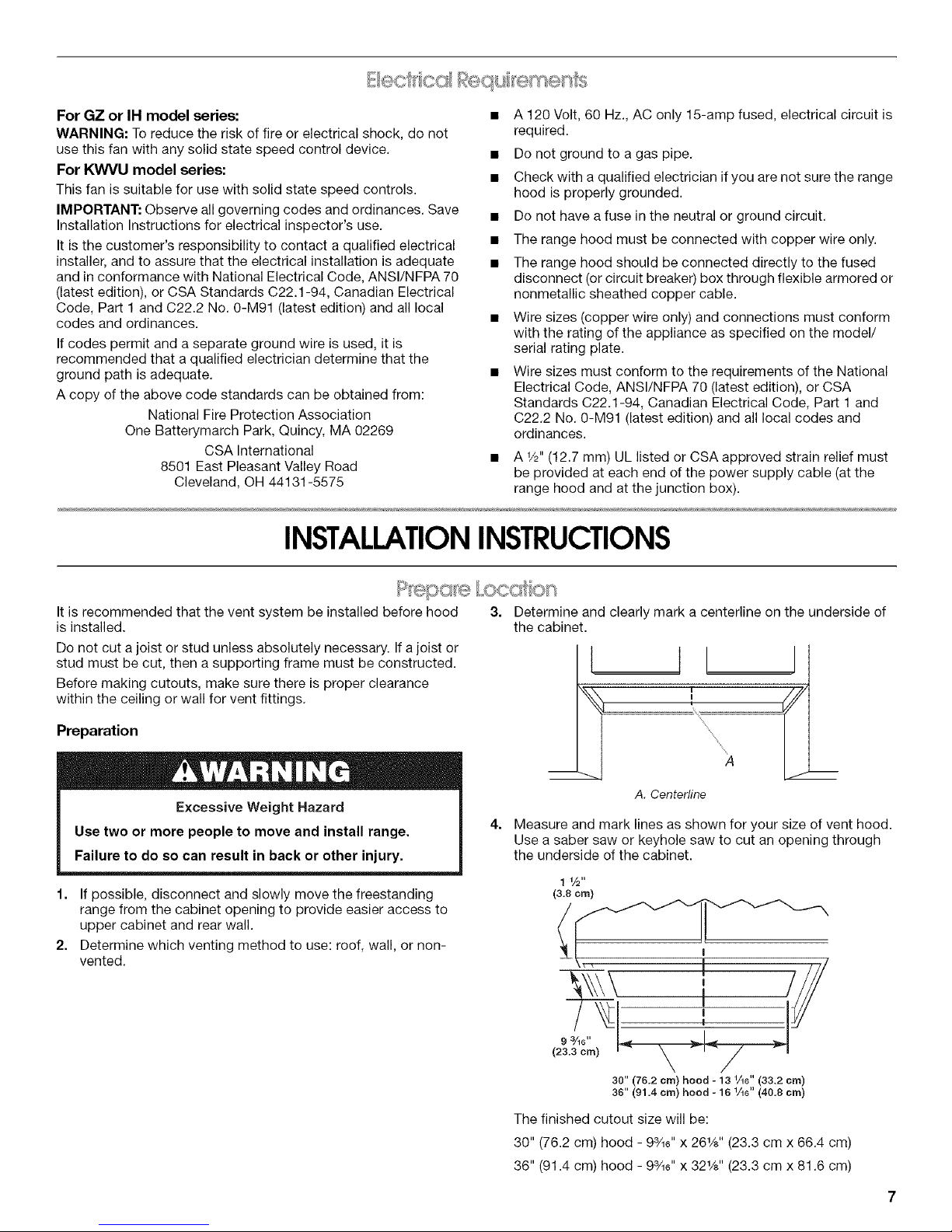
3=
Determine and clearly mark a centerline on the underside of
the cabinet.
xx
xx
m A m
A. Centerline
4. Measure and mark lines as shown for your size of vent hood.
Use a saber saw or keyhole saw to cut an opening through
the underside of the cabinet.
1 1/2"
(3.8 ore)
\\ ///
30" (76.2 cm) hood - 13 1/16" (33.2 cm)
36" (91.4 cm) hood - 16 1/16" (40.8 cm)
The finished cutout size will be:
30" (76.2 cm) hood - 93/_6'' x 26W' (23.3 cm x 66.4 cm)
36" (91.4 cm) hood - 93/_6'' x 32%" (23.3 cm x 81.6 cm)
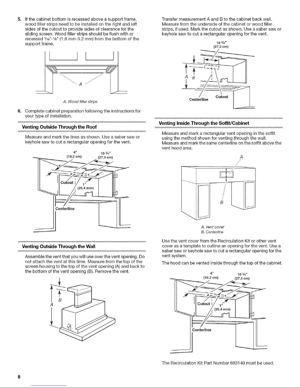
5=
If the cabinet bottom is recessed above a support frame,
wood filler strips need to be installed on the right and left
sides of the cutout to provide sides of clearance for the
sliding screen. Wood filler strips should be flush with or
recessed 1/16"-1/s"(1.6 mm-3.2 mm) from the bottom of the
support frame.
Transfer measurement A and B to the cabinet back wall.
Measure from the underside of the cabinet or wood filler
strips, if used. Mark the cutout as shown. Use a saber saw or
keyhole saw to cut a rectangular opening for the vent.
103/4"
(27.3 cm)
A. Wood filler strips
6. Complete cabinet preparation following the instructions for
your type of installation.
Venting Outside Through the Roof
Measure and mark the lines as shown. Use a saber saw or
keyhole saw to cut a rectangular opening for the vent.
4"
(10.2 cm)
103/4"
(27.3 cm)
C_nte_rline
Centerline
Cutout
Venting Inside Through the Soffit/Cabinet
Measure and mark a rectangular vent opening in the soffit
using the method shown for venting through the wall.
Measure and mark the same centerline on the soffit above the
vent hood area.
B
A. Vent cover
B. Centerline
Venting Outside Through the Wall
Assemble the vent that you will use over the vent opening. Do
not attach the vent at this time. Measure from the top of the
screen housing to the top of the vent opening (A)and back to
the bottom of the vent opening (B). Remove the vent.
Use the vent cover from the Recirculation Kit or other vent
cover as a template to outline an opening for the vent. Use a
saber saw or keyhole saw to cut a rectangular opening for the
vent system.
The hood can be vented inside through the top of the cabinet.
4" 103/4.
Lc._ .I I[lo
The Recirculation Kit Part Number 883140 must be used.
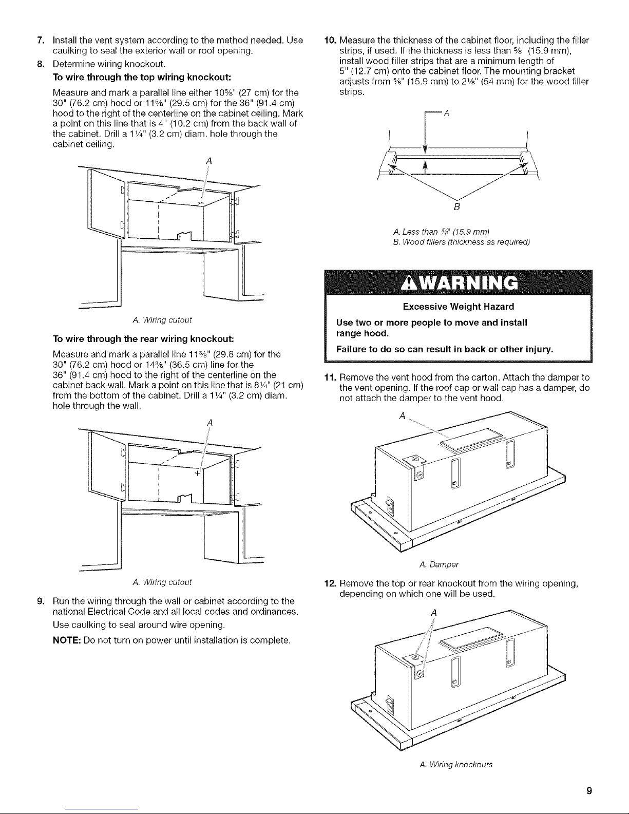
7. Installtheventsystemaccordingtothemethodneeded.Use
caulkingtosealtheexteriorwallorroofopening.
8. Determinewiringknockout.
Towirethroughthetopwiringknockout:
Measure and mark a parallel line either 10%" (27 cm) for the
30" (76.2 cm) hood or 11%" (29.5 cm) for the 36" (91.4 cm)
hood to the right of the centerline on the cabinet ceiling. Mark
a point on this line that is 4" (10.2 cm) from the back wall of
the cabinet. Drill a 11/4"(3.2 cm) diam. hole through the
cabinet ceiling.
A
A. Wiring cutout
10. Measure the thickness of the cabinet floor, including the filler
strips, if used. If the thickness is less than %" (15.9 mm),
install wood filler strips that are a minimum length of
5" (12.7 cm) onto the cabinet floor. The mounting bracket
adjusts from %" (15.9 mm) to 21/8'' (54 mm) for the wood filler
strips.
B
A. Less than _" (15.9 mm)
B. Wood fillers (thickness as required)
To wire through the rear wiring knockout:
Measure and mark a parallel line 11%" (29.8 cm) for the
30" (76.2 cm) hood or 14%" (36.5 cm) line for the
36" (91.4 cm) hood to the right of the centerline on the
cabinet back wall. Mark a point on this line that is 81/4'' (21 cm)
from the bottom of the cabinet. Drill a 11/4"(3.2 cm) diam.
hole through the wall.
A. Wiring cutout
g=
Run the wiring through the wall or cabinet according to the
national Electrical Code and all local codes and ordinances.
Use caulking to seal around wire opening.
NOTE: Do not turn on power until installation is complete.
11. Remove the vent hood from the carton. Attach the damper to
the vent opening. If the roof cap or wall cap has a damper, do
not attach the damper to the vent hood.
A. Damper
12. Remove the top or rear knockout from the wiring opening,
depending on which one will be used.
A
A. Wiring knockouts
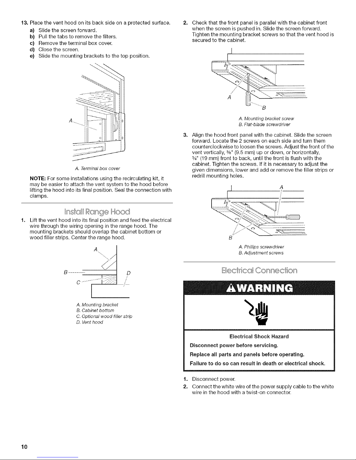
13. Place the vent hood on its back side on a protected surface.
a) Slide the screen forward.
b) Pull the tabs to remove the filters,
c) Remove the terminal box cover.
d} Close the screen.
e) Slide the mounting brackets to the top position.
A. Terminal box cover
NOTE: For some installations using the recirculating kit, it
may be easier to attach the vent system to the hood before
lifting the hood into its final position, Seal the connection with
clamps.
2.
Check that the front panel is parallel with the cabinet front
when the screen is pushed in. Slide the screen forward.
Tighten the mounting bracket screws so that the vent hood is
secured to the cabinet.
.......i
........
A___ _ .....
A. Mounting bracket screw
B. Flat-blade screwdriver
3.
Align the hood front panel with the cabinet. Slide the screen
forward. Locate the 2 screws on each side and turn them
counterclockwise to loosen the screws. Adjust the front of the
vent vertically, %" (9.5 mm) up or down, or horizontally,
3/4"(19 mm) front to back, until the front is flush with the
cabinet. Tighten the screws. If it is necessary to adjust the
given dimensions, lower and add or remove the filler strips or
redrill mounting holes.
I /_
Lift the vent hood into its final position and feed the electrical
wire through the wiring opening in the range hood. The
mounting brackets should overlap the cabinet bottom or
wood filler strips. Center the range hood.
A
A. Mounting bracket
B. Cabinet bottom
C. Optional wood filler strip
D. Vent hood
B
A. Phillips screwdriver
B. Adjustment screws
Electrical Shock Hazard
Disconnect power before servicing.
Replace all parts and panels before operating.
Failure to do so can result in death or electrical shock.
1. Disconnect power.
2. Connect the white wire of the power supply cable to the white
wire in the hood with a twist-on connector.
10
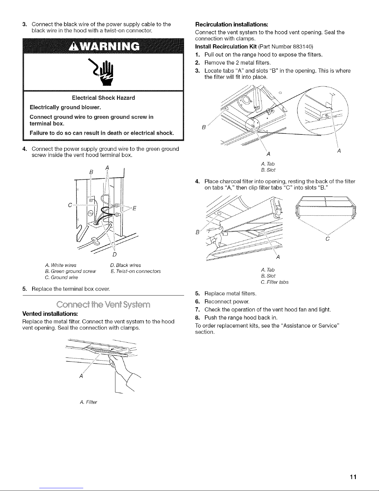
3. Connect the black wire of the power supply cable to the
black wire in the hood with a twist-on connector.
Electrical Shock Hazard
Electrically ground blower.
Connect ground wire to green ground screw in
terminal box.
Failure to do so can result in death or electrical shock.
Recirculation installations:
Connect the vent system to the hood vent opening. Seal the
connection with clamps.
Install Recirculation Kit (Part Number 883140)
1. Pull out on the range hood to expose the filters.
2. Remove the 2 metal filters.
3. Locate tabs "A" and slots "B" in the opening. This is where
the filter will fit into place.
B '/
4. Connect the power supply ground wire to the green ground
screw inside the vent hood terminal box.
B
C
A. White wires
B. Green ground screw
C. Ground wire
D. Black wires
E.Twist-on connectors
5. Replace the terminal box cover.
Vented installations:
Replace the metal filter. Connect the vent system to the hood
vent opening. Seal the connection with clamps.
A
A. Tab
B. Slot
4.
Place charcoal filter into opening, resting the back of the filter
on tabs "A," then clip filter tabs "C" into slots "B."
A. Tab
B. Slot
C. Filter tabs
5. Replace metal filters.
6. Reconnect power.
7. Check the operation of the vent hood fan and light.
8. Push the range hood back in.
To order replacement kits, see the "Assistance or Service"
section.
A. Filter
11
 Loading...