

Whirlpool KECT 365, KECT 305 Installation Instructions Manual
ELECTRIC GLASS SURFACE
BUILT-IN COOKTOPS
36” MODEL: KECT365
30” MODEL: KECT305
INSTALLATION
INSTRUCTIONS
INSTALLER: FINAL CHECKLIST
IMPORTANT:
LEAVE THESE INSTRUCTIONS FOR USE BY
THE LOCAL ELECTRICAL INSPECTOR
PLACEMENT OF COOKTOP
Cl 1. Specified clearances maintained to adjacent surfaces.
0 2. Unit secure to countertop.
ELECTRICAL
Cl 1. Unit properly grounded.
El 2. Check that unit is connected to proper volt, amp and breaker ratings per
Electrical Specifications given in this booklet.
Cl 3. All connections made in accordance with local and/or National Electrical Code.
OPERATIONAL
Cl 1. Knobs installed on switches.
Cl 2. Individual element indicator light comes on when the element is turned on.
Unless instructed to leave for owner, remove all tags, labels, and internal packing
material.
THANK YOU INSTALLER:
1. Complete Installation Checklist.
2. Leave all literature for customer.
3. Notify dealer that installation is completed.
FOR DETAILED INSTRUCTIONS, FOLLOW METHODS DESCRIBED IN THIS FOLDER.
IMPORTANT:
Read completely before installing to save time, work,
assure proper performance, and owner’s warranty protection.
ELECTRICAL SPECIFICATIONS
KECT 365
KECT 305
Voltage and Frequency 240 volts 60 Hertz
240 volts 60 Hertz
Maximum Watts 8100 watts
7ooo watts
Operating Load
33.75 amperes
29.2 amperes
Maximum
Device Size
40 amperes
40 amperes
Minimum Circuit Size 40 amperes
40 amperes
WARNING:
ELECTRICAL AND GROUNDING CONNECTIONS MUST COMPLY WITH APPLICABLE
PORTIONS OF THE NATIONAL ELECTRICAL CODE AND/OR OTHER LOCAL ELECTRICAL CODES.
The bare copper wire in factory installed conduit is the unit ground wire, not a neutral conductor.
INSTALLATION INSTRUCTIONS
All work should be done by a qualified electrician who is familiar with the National Electrical Code and/or Local Codes.
WARNING:
DISCONNECT ELECTRICAL POWER SUPPLY AND PLACE A TAG AT THE DISCONNECT SWITCH
INDICATING THAT YOU ARE WORKING ON THE CIRCUIT.
Before installing unit be sure that the electrical supply meets the electrical specifications given in this booklet.
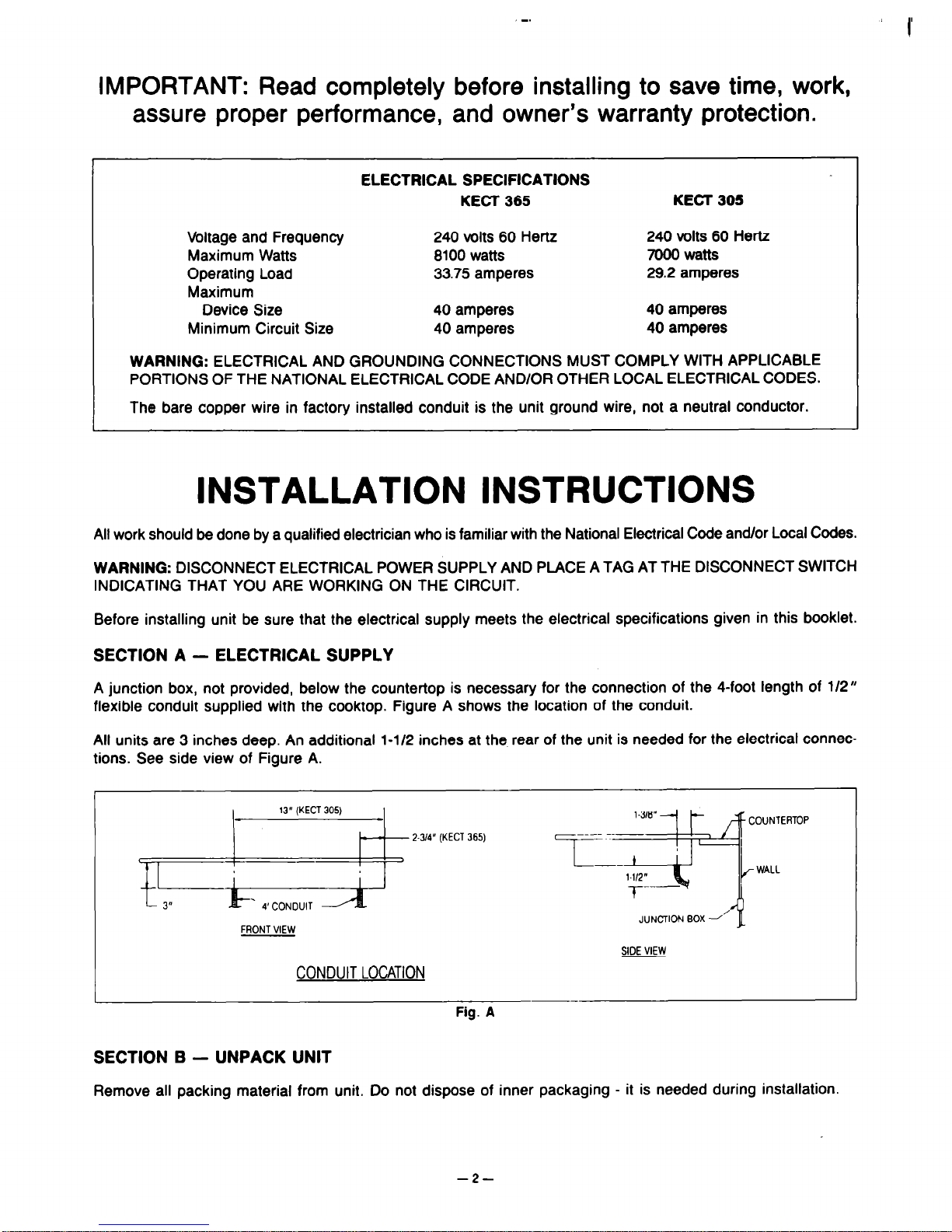
SECTION A - ELECTRICAL SUPPLY
A junction box, not provided, below the countertop is necessary for the connection of the 4-foot length of 112”
flexible conduit supplied with the cooktop. Figure A shows the location of the conduit.
All units are 3 inches deep. An additional l-112 inches at the. rear of the unit is needed for the electrical connections. See side view of Figure A.
FRONT VIEW
CONDUIT LOCATION
SIDE VIEW
Fig. A
SECTION B - UNPACK UNIT
Remove all packing material from unit. Do not dispose of inner packaging - it is needed during installation
-2-
 Loading...