


®
®
ELECTRONIC
ELECTRIC DRYER
Use&CareGuide
For questions about features, operation/performance, parts, accessories or service, call: 1-800-253-1301
or visit our website at... www.whirlpool.com
Table of Contents ................................................ |
2 |
8577193

TABLE OF CONTENTS
DRYER SAFETY.............................................................................. |
3 |
INSTALLATION INSTRUCTIONS .................................................. |
4 |
Tools and Parts ............................................................................ |
4 |
Options......................................................................................... |
4 |
Location Requirements................................................................ |
5 |
Electrical Requirements ............................................................... |
7 |
Electrical Connection ................................................................... |
8 |
Venting Requirements................................................................ |
13 |
Plan Vent System....................................................................... |
14 |
Install Vent System..................................................................... |
15 |
Install Leveling Legs................................................................... |
16 |
Connect Vent.............................................................................. |
16 |
Level Dryer ................................................................................. |
16 |
Complete Installation ................................................................. |
16 |
DRYER USE .................................................................................. |
17 |
Starting Your Dryer..................................................................... |
17 |
Stopping Your Dryer................................................................... |
18 |
Pausing or Restarting................................................................. |
18 |
Control Locked........................................................................... |
18 |
Drying and Cycle Tips ................................................................ |
18 |
Status Lights............................................................................... |
19 |
Cycles......................................................................................... |
19 |
Additional Features .................................................................... |
20 |
Drying Rack ................................................................................ |
21 |
DRYER CARE............................................................................... |
22 |
Cleaning the Dryer Location....................................................... |
22 |
Cleaning the Lint Screen ............................................................ |
22 |
Cleaning the Dryer Interior ......................................................... |
22 |
Removing Accumulated Lint...................................................... |
22 |
Vacation and Moving Care......................................................... |
23 |
Changing the Drum Light ........................................................... |
23 |
TROUBLESHOOTING .................................................................. |
24 |
ASSISTANCE OR SERVICE......................................................... |
26 |
WARRANTY .................................................................................. |
28 |
2

DRYER SAFETY
Your safety and the safety of others are very important.
We have provided many important safety messages in this manual and on your appliance. Always read and obey all safety messages.
This is the safety alert symbol.
This symbol alerts you to potential hazards that can kill or hurt you and others.
All safety messages will follow the safety alert symbol and either the word “DANGER” or “WARNING.” These words mean:
 DANGER
 WARNING
You can be killed or seriously injured if you don't immediately follow instructions.
You can be killed or seriously injured if you don't follow instructions.
All safety messages will tell you what the potential hazard is, tell you how to reduce the chance of injury, and tell you what can happen if the instructions are not followed.
IMPORTANT SAFETY INSTRUCTIONS
WARNING: To reduce the risk of fire, electric shock, or injury to persons when using the dryer, follow basic precautions, including the following:
■ Read all instructions before using the dryer. |
■ Do not repair or replace any part of the dryer or attempt |
|
■ Do not place items exposed to cooking oils in your dryer. |
any servicing unless specifically recommended in this |
|
Items contaminated with cooking oils may contribute to |
Use and Care Guide or in published user-repair |
|
a chemical reaction that could cause a load to catch fire. |
instructions that you understand and have the skills to |
|
■ Do not dry articles that have been previously cleaned in, |
carry out. |
|
■ Do not use fabric softeners or products to eliminate static |
||
washed in, soaked in, or spotted with gasoline, dry- |
||
unless recommended by the manufacturer of the fabric |
||
cleaning solvents, or other flammable or explosive |
||
softener or product. |
||
substances as they give off vapors that could ignite or |
||
■ Do not use heat to dry articles containing foam rubber or |
||
explode. |
||
■ Do not allow children to play on or in the dryer. Close |
similarly textured rubber-like materials. |
|
■ Clean lint screen before or after each load. |
||
supervision of children is necessary when the dryer is |
||
used near children. |
■ Keep area around the exhaust opening and adjacent |
|
■ Before the dryer is removed from service or discarded, |
surrounding areas free from the accumulation of lint, dust, |
|
remove the door to the drying compartment. |
and dirt. |
|
■ Do not reach into the dryer if the drum is moving. |
■ The interior of the dryer and exhaust vent should be |
|
■ Do not install or store the dryer where it will be exposed |
cleaned periodically by qualified service personnel. |
|
■ See installation instructions for grounding requirements. |
||
to the weather. |
||
■ Do not tamper with controls. |
|
SAVE THESE INSTRUCTIONS
3
INSTALLATION INSTRUCTIONS
ToolsandParts
Gather the required tools and parts before starting installation. Read and follow the safety instructions provided with any tools listed here.
■Flat-blade screwdriver
■#2 Phillips screwdriver
■Adjustable wrench that opens to 1" (2.5 cm) or hex-head socket wrench (for adjusting dryer feet)
■Wire stripper (direct wire installations)
■Level
Parts supplied
■Vent clamps
■Caulking gun and compound (for installing new exhaust vent)
■Tin snips (new vent installations)
■Tape measure
■¼" nut driver (recommended)
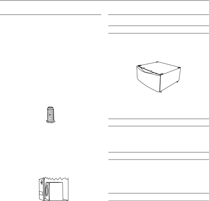
Remove parts packages from dryer drum. Check that all parts are included.
■Parts package
4 Leveling legs
NOTE: Do not use leveling legs if installing the dryer on a pedestal.
Parts needed
Check local codes. Check existing electrical supply and venting. See “Electrical Requirements” and “Venting Requirements” before purchasing parts.
■For close-clearance installations between 31.5" (80.01 cm) and 37" (93.98 cm), see “Plan Vent System” section for venting requirements.

 37"
37" 
 (93.98 cm)
Mobile home installations require metal exhaust system hardware available for purchase from the dealer from whom you purchased your dryer. For further information, please refer to the “Assistance or Service” section of this manual.
Options
Pedestal
Are you placing the dryer on a pedestal? You may purchase a pedestal separately for this dryer. This pedestal will add about 13" (33 cm) to the height of your unit for a total height of approximately 51" (130 cm).
For a garage installation, you will need to place the pedestal at least 6" (22.9 cm) above the floor.
Optional pedestal
To order, call the dealer from whom you purchased your dryer or refer to the “Assistance or Service” section of this manual. Ask for Part Number LAB2700MQ (White), LAB2700MT (Biscuit) or LAB2700ML (Pewter).
Stack Kit
Are you planning to stack your DUET® washer and dryer? To do so, you will need to purchase a Stack Kit.
To order, call the dealer from whom you purchased your dryer or refer to the “Assistance or Service” section of this manual. Ask for Part Number 8541503.
Door Reversal Kit
Are you planning to reverse the door swing direction on your DUET® dryer? To do so, you will need to purchase a Door Reversal Kit.
To order, call the dealer from whom you purchased your dryer or refer to the “Assistance or Service” section of this manual. Ask for Part Number 8530069 (Shield Blue), 8530070 (Shield Platinum), 8530071 (Biscuit) or 8530072 (Pewter).
Door Reversal and Stack Combination Kit
Are you planning to reverse the door swing direction on your DUET® dryer and stack your DUET® washer and dryer? To do so, you can purchase a Door Reversal and Stack Combination Kit.
To order, call the dealer from whom you purchased your dryer or refer to the “Assistance or Service” section of this manual. Ask for Part Number 8530073 (Shield Blue), 8530074 (Shield Platinum), 8530075 (Biscuit) or 8530076 (Pewter).
4
LocationRequirements
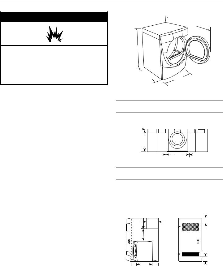
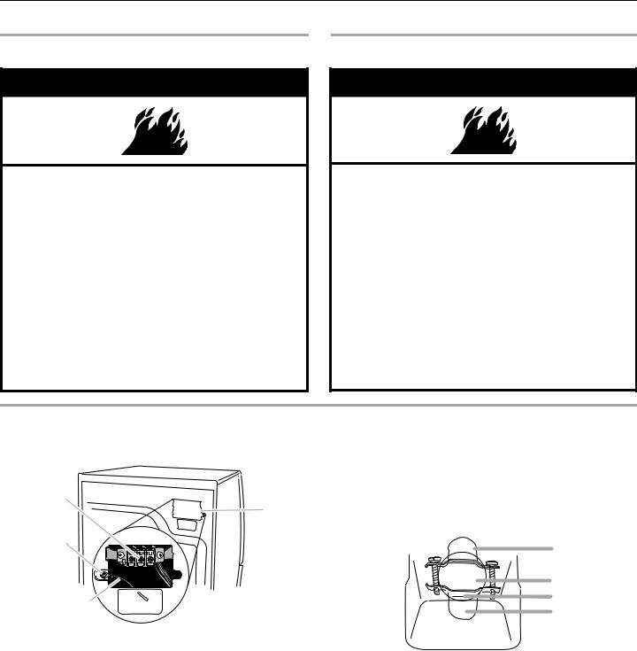
 WARNING
Explosion Hazard
Keep flammable materials and vapors, such as gasoline, away from dryer.
Place dryer at least 18 inches (46 cm) above the floor for a garage installation.
Failure to do so can result in death, explosion, or fire.
You will need
■A location that allows for proper exhaust installation. See “Venting Requirements.”
■A separate 30-amp circuit.
■If you are using a power supply cord, a grounded electrical outlet located within 2 ft (61 cm) of either side of the dryer. See “Electrical Requirements.”
■A sturdy floor to support the total dryer weight of 200 lbs (90.7 kg). The combined weight of a companion appliance should also be considered.
■A level floor with a maximum slope of 1" (2.5 cm) under entire dryer. If slope is greater than 1" (2.5 cm), install Extended Dryer Feet Kit, Part Number 279810. Clothes may not tumble properly and automatic sensor cycles may not operate correctly if dryer is not level.
■For a garage installation, you will need to place the dryer at least 18" (46 cm) above the floor. If using a pedestal, you will need to place the pedestal at least 6" (22.9 cm) above the floor.
Do not operate your dryer at temperatures below 45ºF (7ºC). At lower temperatures, the dryer might not shut off at the end of an automatic cycle. This can result in longer drying times.
The dryer must not be installed or stored in an area where it will be exposed to water and/or weather.
Check code requirements. Some codes limit, or do not permit, installation of the dryer in garages, closets, mobile homes or sleeping quarters. Contact your local building inspector.
Installation clearances
■The location must be large enough to allow the dryer door to open fully.
■Additional spacing should be considered for ease of installation and servicing.
■Additional clearances might be required for wall, door and floor moldings.
■Additional spacing of 1" (2.5 cm) on all sides of the dryer is recommended to reduce noise transfer.
■Companion appliance spacing should also be considered.
Dryer Dimensions
 51½" (130.81 cm)
38" (96.52 cm)
*31½"
(80 cm)
27" (68.6 cm)
*Most installations require a minimum 5½" (14 cm) clearance behind the dryer for the exhaust vent with elbow. See “Venting Requirements.”
Minimum installation spacing for custom undercounter installation
The dimensions shown are for the minimum spacing allowed.
Custom undercounter installation - Dryer only
0" 
 (0 cm)
38" min. (96.52 cm)
0"* |
|
27" |
|
0"* |
(0 cm) |
|
(68.6 cm) |
(0 cm) |
|
*Additional spacing recommended
Minimum installation spacing for recessed or closet installation, with or without a pedestal
■The dimensions shown are for the minimum spacing allowed.
■For closet installation, with a door, minimum ventilation openings in the top and bottom of the door are required. Louvered doors with equivalent ventilation openings are acceptable.
Closet installation - Dryer only
|
|
|
|
|
3" |
|
14" max. |
|
|
(7.6 cm) |
|
|
48 in.2 |
|
|
||
|
(35.6 cm) |
|
|
||
|
|
|
(310 cm2) |
|
|
|
18" min. |
|
|
|
|
|
(45.72 cm) |
|
|
|
|
|
|
|
24 in.2 |
2) |
|
|
|
|
(155 cm |
3" |
|
|
|
|
|
|
(7.6 cm) |
1" |
31½" |
0"* |
|
|
|
(2.5 cm) (80 cm) |
(0 cm) |
|
|
|
|
|
A |
|
|
|
B |
A.Side view - closet or confined area
B.Closet door with vents
*Side or bottom venting - additional spacing recommended
5
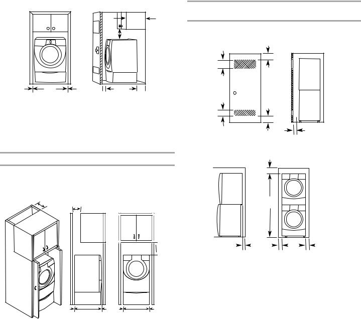
Recessed or closet installation - Dryer on pedestal
|
|
|
|
|
14" max. |
|
|
|
|
|
(35.6 cm) |
|
|
|
|
18" min. |
|
|
|
|
|
(45.72 cm) |
|
0"* |
27" |
0"* |
1" |
31½" |
0"** |
(0 cm) |
(68.6 cm) |
(0 cm) |
(2.5 cm) |
(80 cm) |
(0 cm) |
|
A |
|
|
B |
|
A.Recessed area
B.Side view - closet or confined area
*Additional spacing recommended
**Side or bottom venting - additional spacing recommended
Minimum installation spacing for cabinet installation
■The dimensions shown are for the minimum spacing allowed.
■For cabinet installation, with a door, minimum ventilation openings in the top of the cabinet are required.
7" (17.8 cm) |
7" (17.8 cm) |
|
|
|
|
|
|
|
 9"
9"
 (22.9 cm)
|
|
|
1" |
|
|
|
|
|
|
|
|
|
|
|
|
|
|
|
|
|
|
|
|
|
|
|
|
|
|
|
|
|
|
|
|
0"** |
31¹" |
0"* |
27" |
0"* |
||||
|
(0 cm) |
(80.0 cm) (2.5 cm) |
(0 cm)(68.6 cm) (0 cm) |
|||||
*Side or bottom venting - additional spacing recommended
**Additional spacing recommended
Recommended installation spacing for recessed or closet installation, with stacked washer and dryer
The dimensions shown are for the recommended spacing.
48 in.2 *
(310 cm2)
3" (7.6 cm)
|
3" (7.6 cm) |
24 in.2 * |
1" (2.5 cm) |
(155 cm2) |
|
*Min. top and bottom air openings for closet door.
6" (15.2 cm)
76" (193 cm)
5½"** |
|
|
|
1"*** |
|
|
|
27" |
|
|
|
1"*** |
|
|
|
|
|
|
|||||||
(14 cm) |
|
|
|
(2.5 cm) |
|
(68.6 cm) |
|
(2.5 cm) |
||||
**External exhaust elbow requires additional space.
***Wall, door and floor molding may require additional spacing.
Mobile home - Additional installation requirements
This dryer is suitable for mobile home installations. The installation must conform to the Manufactured Home Construction and Safety Standard, Title 24 CFR, Part 3280 (formerly the Federal Standard for Mobile Home Construction and Safety, Title 24, HUD Part 280) or Standard CAN/CSA-Z240 MH.
Mobile home installations require:
■Metal exhaust system hardware, which is available for purchase from your dealer.
■Special provisions must be made in mobile homes to introduce outside air into the dryer. The opening (such as a nearby window) should be at least twice as large as the dryer exhaust opening.
6
ElectricalRequirements
It is your responsibility
■To contact a qualified electrical installer.
■To be sure that the electrical connection is adequate and in conformance with the National Electrical Code, ANSI/NFPA 70-latest edition and all local codes and ordinances.
The National Electric Code requires a 4-wire supply connection for homes built after 1996, dryer circuits involved in remodeling after 1996, and all mobile home installations.
A copy of the above code standards can be obtained from: National Fire Protection Association, One Batterymarch Park, Quincy, MA 02269.
■To supply the required 3 or 4 wire, single phase, 120/240 volt, 60 Hz., AC only electrical supply (or 3 or 4 wire, 120/208 volt electrical supply, if specified on the serial/rating plate) on a separate 30-amp circuit, fused on both sides of the line. A time-delay fuse or circuit breaker is recommended. Connect to an individual branch circuit. Do not have a fuse in the neutral or grounding circuit.
■Do not use an extension cord.
■If codes permit and a separate ground wire is used, it is recommended that a qualified electrician determine that the ground path is adequate.
Electrical Connection
To properly install your dryer, you must determine the type of electrical connection you will be using and follow the instructions provided for it here.
■This dryer is manufactured ready to install with a 3-wire electrical supply connection. The neutral ground wire is permanently connected to the neutral conductor (white wire) within the dryer. If the dryer is installed with a 4-wire electrical supply connection, the neutral ground wire must be removed from the external ground conductor screw (green screw), and secured under the neutral terminal (center or white wire) of the terminal block. When the neutral ground wire is secured under the neutral terminal (center or white wire) of the terminal block, the dryer cabinet is isolated from the neutral conductor.
■If local codes do not permit the connection of a neutral ground wire to the neutral wire, see “Optional 3-wire connection” section.
■A 4-wire power supply connection must be used when the appliance is installed in a location where grounding through the neutral conductor is prohibited. Grounding through the neutral is prohibited for (1) new branch-circuit installations, (2) mobile homes, (3) recreational vehicles, and (4) areas where local codes prohibit grounding through the neutral conductors.
If using a power supply cord:
Use a UL listed power supply cord kit marked for use with clothes dryers. The kit should contain:
■A UL listed 30-amp power supply cord, rated
120/240 volt minimum. The cord should be type SRD or SRDT and be at least 4 ft (1.22 m) long. The wires that connect to the dryer must end in ring terminals or spade terminals with upturned ends.
■A UL listed strain relief.
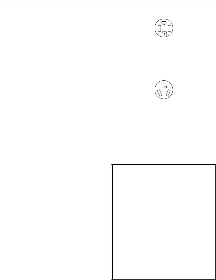
If your outlet looks like this:
4-wire receptacle (14-30R)
Then choose a 4-wire power supply cord with ring or spade terminals and UL listed strain relief. The 4-wire power supply cord, at least 4 ft (1.22 m) long, must have four 10-gauge copper wires and match a 4-wire receptacle of NEMA Type
14-30R. The ground wire (ground conductor) may be either green or bare. The neutral conductor must be identified by a white cover.
If your outlet looks like this:
3-wire receptacle (10-30R)
Then choose a 3-wire power supply cord with ring or spade terminals and UL listed strain relief. The 3-wire power supply cord, at least 4 ft (1.22 m) long, must have three 10-gauge copper wires and match a 3-wire receptacle of NEMA Type 10-30R.
If connecting by direct wire:
Power supply cable must match power supply (4-wire or 3-wire) and be:
■Flexible armored cable or nonmetallic sheathed copper cable (with ground wire), protected with flexible metallic conduit. All current-carrying wires must be insulated.
■10-gauge solid copper wire (do not use aluminum).
■At least 5 ft (1.52 m) long.
GROUNDING INSTRUCTIONS
■ For a grounded, cord-connected dryer:
This dryer must be grounded. In the event of malfunction or breakdown, grounding will reduce the risk of electric shock by providing a path of least resistance for electric current.
This dryer uses a cord having an equipment-grounding conductor and a grounding plug. The plug must be plugged into an appropriate outlet that is properly installed and grounded in accordance with all local codes and ordinances.
■ For a permanently connected dryer:
This dryer must be connected to a grounded metal, permanent wiring system, or an equipment-grounding conductor must be run with the circuit conductors and connected to the equipment-grounding terminal or lead on the dryer.
WARNING: Improper connection of the equipmentgrounding conductor can result in a risk of electric shock. Check with a qualified electrician or service representative or personnel if you are in doubt as to whether the dryer is properly grounded. Do not modify the plug on the power supply cord: if it will not fit the outlet, have a proper outlet installed by a qualified electrician.
SAVE THESE INSTRUCTIONS
7
ElectricalConnection
Power Supply Cord |
|
Direct Wire |
 WARNING
Fire Hazard
Use a new UL listed 30 amp power supply cord.
Use a UL listed strain relief.
Disconnect power before making electrical connections.
Connect neutral wire (white or center wire) to center terminal (silver).
Ground wire (green or bare wire) must be connected to green ground connector.
Connect remaining 2 supply wires to remaining 2 terminals (gold).
Securely tighten all electrical connections.
Failure to do so can result in death, fire, or electrical shock.
 WARNING
Fire Hazard
Use 10 gauge solid copper wire.
Use a UL listed strain relief.
Disconnect power before making electrical connections.
Connect neutral wire (white or center wire) to center terminal (silver).
Ground wire (green or bare wire) must be connected to green ground connector.
Connect remaining 2 supply wires to remaining 2 terminals (gold).
Securely tighten all electrical connections.
Failure to do so can result in death, fire, or electrical shock.
1.Disconnect power.
2.Remove the hold-down screw and terminal block cover.
C
D
B
A
A.Neutral ground wire
B.External ground conductor screw
C.Center, silver-colored terminal block screw
D.Terminal block cover and hold-down screw
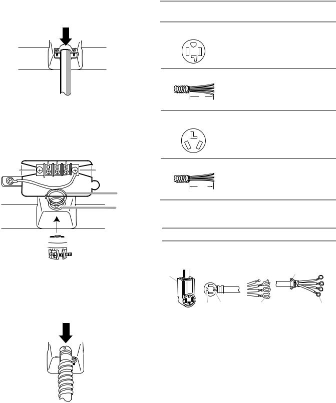
3.Install strain relief.
Style 1: Power supply cord strain relief
■Remove the screws from a ³⁄" (1.9 cm) UL listed strain relief (UL marking on strain relief). Put the tabs of the two clamp sections into the hole below the terminal block opening so that one tab is pointing up and the other is pointing down, and hold in place. Tighten strain relief screws just enough to hold the two clamp sections together.
 A
A
 B
B
 C
C
 D
D
A.Strain relief tab pointing up
B.Hole below terminal block opening
C.Clamp section
D.Strain relief tab pointing down
8
■Put power supply cord through the strain relief. Be sure that the wire insulation on the power supply cord is inside the strain relief. The strain relief should have a tight fit with the dryer cabinet and be in a horizontal position. Do not further tighten strain relief screws at this point.
Style 2: Direct wire strain relief
■Unscrew the removable conduit connector and any screws from a ³⁄" (1.9 cm) UL listed strain relief (UL marking on strain relief). Put the threaded section of the strain relief through the hole below the terminal block opening. Reaching inside the terminal block opening, screw the removable conduit connector onto the strain relief threads.
 A
A
B
 C
C
A.Removable conduit connector
B.Hole below terminal block opening
C.Strain relief threads
■Put direct wire cable through the strain relief. The strain relief should have a tight fit with the dryer cabinet and be in a horizontal position. Tighten strain relief screw against the direct wire cable.
4.Now complete installation following instructions for your type of electrical connection:
4-wire (recommended)
3-wire (if 4-wire is not available)
Electrical Connection Options
If your home has: |
And you will be |
Go to Section |
|
connecting to: |
|
4-wire receptacle |
A UL listed, |
4-wire connection: |
(NEMA Type 14-30R) |
120/240-volt |
Power supply cord |
|
minimum, |
|
|
30-amp, dryer |
|
|
power supply |
|
|
cord* |
|
4-wire direct |
A fused |
4-wire connection: |
|
disconnect or |
Direct Wire |
|
circuit breaker |
|
5" |
box* |
|
|
|
|
(12.7 cm) |
|
|
3-wire receptacle |
A UL listed, |
3-wire connection: |
(NEMA type 10-30R) |
120/240-volt |
Power supply cord |
|
minimum, |
|
|
30-amp, dryer |
|
|
power supply |
|
|
cord* |
|
3-wire direct |
A fused |
3-wire connection: |
|
disconnect or |
Direct Wire |
|
circuit breaker |
|
3¹⁄" |
box* |
|
(8.9 cm) |
|
|
*If local codes do not permit the connection of a frame-grounding conductor to the neutral wire, go to “Optional 3-wire connection” section.
4-wire connection: Power supply cord
IMPORTANT: A 4-wire connection is required for mobile homes and where local codes do not permit the use of 3-wire connections.
B F A 

C D E G
A.4-wire receptacle (NEMA type 14-30R) B. 4-prong plug
C. Ground prong D. Neutral prong
E. Spade terminals with upturned ends F. ¾" (1.9 cm) UL listed strain relief
G. Ring terminals
9
 Loading...