

Whirlpool AWP 093, AWP 1200 INSTALLATION
GB QUICK REFERENCE GUIDE
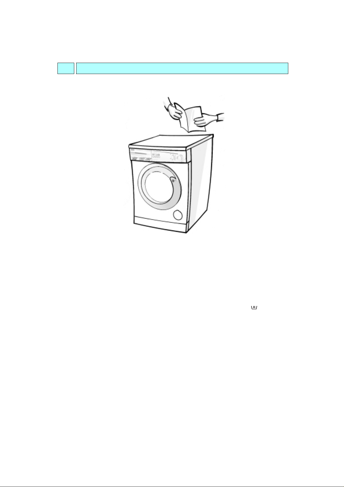
BEFORE USING THE APPLIANCE FOR THE FIRST TIME
• IMPORTANT: MAKE SURE YOU HAVE READ THE INSTALLATION INSTRUCTIONS.
• REMOVE THE TRANSIT BOLTS BEFORE USING THE MACHINE FOR THE FIRST
TIME.
• First wash cycle without laundry:
1.
Open the tap(s).
2.
Close the door.
3.
Pour a little detergent (about 100 ml) into the detergent compartment .
4.
Select a short wash programme (see programme chart).
5.
Press the “ON/OFF” button.
This will remove any water remaining in the machine from the manufacturer's test run.
ROUTINE WASHES:
1.
Open the tap(s).
2.
Sort the laundry according to fabric type and colour and load the machine.
3.
Close the door.
4.
Add detergent and any additives required.
5.
Select the programme, temperature and special options (depending on model).
6.
Press the “ON/OFF” button.
20

CONTENTS GB
INSTALLATION INSTRUCTIONS
APPLIANCE AND ACCESSORIES
PROTECTING THE ENVIRONMENT
SAFETY INSTRUCTIONS
MOVING AND TRANSPORTING THE APPLIANCE
SORTING THE WASH
DETERGENT AND ADDITIVES
DYEING AND BLEACHING
SELECTING THE PROGRAMME AND
SPECIAL OPTIONS / PROGRAMME START
PAGE
PAGE
PAGE
PAGE
PAGE
PAGE
PAGE
PAGE
PAGE
22
28
29
29
29
30
31
32
33
DOOR LOCK / PROGRAMME END /
PROGRAMME RESELECTION
REMOVING THE FILTER /
DRAINING RESIDUAL WATER
CARE AND MAINTENANCE
TROUBLE-SHOOTING GUIDE
AFTER-SALES SERVICE
PAGE
PAGE
PAGE
PAGE
PAGE
34
34
35
36
36
21
INSTALLATION INSTRUCTIONS
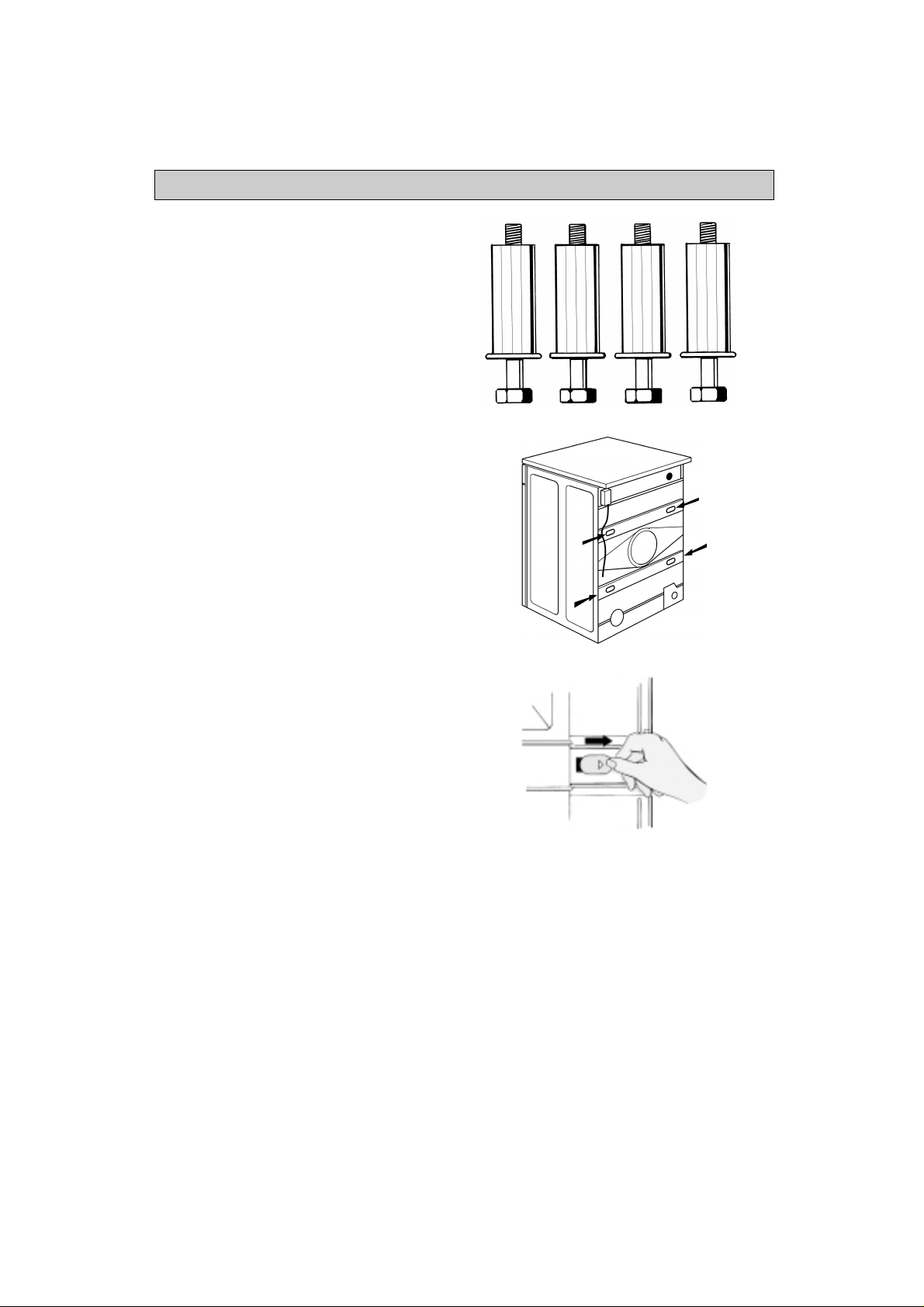
TRANSIT BOLTS
The appliance is fitted with transit bolts to prev ent
internal damage while it is being moved.
Before using the appliance the transit bolts
MUST be removed (Fig. 1).
1.
Slacken the bolts with the spanner supplied
(Fig. 2).
2.
Move the bolt to the centre of the hole
(Fig. 3).
3.
Completely extract the bolt and the coloured
plastic spacer (Fig. 4).
4.
Plug the hole using the plastic cap provided
(Fig. 5).
5.
Repeat the above operations for the other
3 bolts.
Note
Fit the transit bolts before tr ans po rt in g th e
appliance as follows:
1.
Pry up the plastic caps with a screwdriver,
slide them out against the direction indicated
with the arrow and remove them.
2.
Fit the transit bolts by following the above
procedure in reverse order.
Fig. 1
Fig. 2
22
Fig. 3
INSTALLATION INSTRUCTIONS
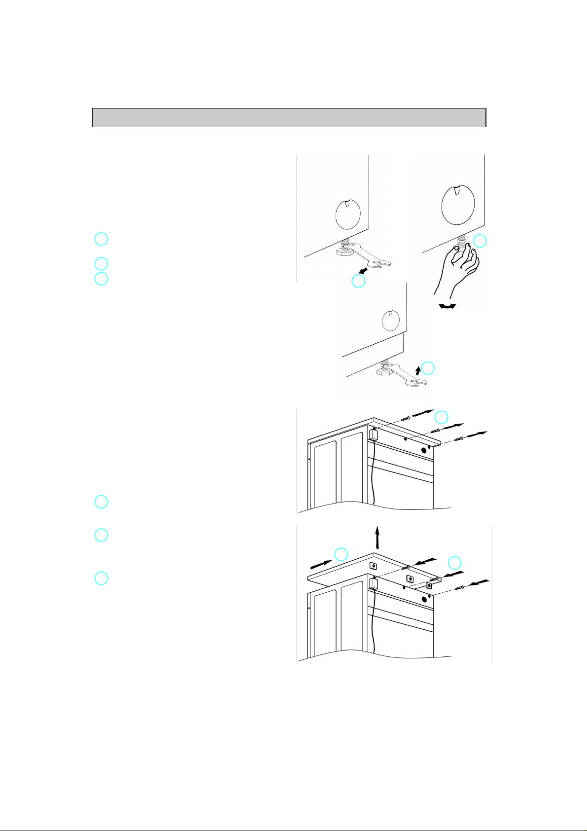
INSTALLATION
•
Install the appliance on a solid and level floor
surface, preferably in a corner of the room.
•
Make sure that all four feet are resting firmly
on the floor and check that the appliance is
perfectly level (use a spirit level).
•
If the floor is uneven, adjust the levelling feet
as required (do not insert pieces of wood,
cardboard etc. under the feet).
Slacken the locknut using the spanner
1.
supplied.
Adjust the height of the foot, turning it by hand.
2.
Tighten the locknut anticlockwise towards
3.
the washing machine.
•
If the appliance is to be installed on a wooden
floor, distribute the weight by placing it on a
60x60 cm sheet of plywood at least 3 cm in
thickness. Secure the plywood sheet to the
floor.
2
1
3
BUILD-UNDER / WORKTOP
The appliance must be installed only under a
fitted, continuous kitchen worktop.
The appliance must only be built under using
the built under set UBS.
•
Unplug the appliance from the mains.
Unscrew the worktop fixing screws (2 or 3
1.
screws dependent on the model) from the
rear of the appliance.
Slide the worktop fully backward and lift it
2.
upwards to remove.
Install the cover panel following the relative
instructions.
3.
Refit the fixing screws and tighten them.
BUILD-UNDER OPENING DIMENSIONS
Width 600 mm
Height 825 mm
Depth 600 mm
WARNING:
Only plug the machine into the ma ins p owe r
socket after you have fitted the c over panel or the
machine worktop.
1
2
3
23

INSTALLATION INSTRUCTIONS
WATER SUPPLY
•
Water supply: only cold water.
•
Tap: 3/4” threaded hose connector.
•
Water pressure (mains pressure):
10-100 N/cm2 (100 kPa-1000 kPa).
For Great Britain and Ireland only
•
Water inlet: hot and cold fill. The warm water
inlet temperature must not exceed 60°C.
INLET HOSE(S)
Note: If the inlet hose is already fitted to the rear
panel on the appliance, ignore points 1 and 4.
1.
Remove the inlet hose from the drum.
2.
Fit the mesh filter supplied in the thread
between the straight end of the inlet hose(s)
and the tap(s).
3.
Carefully screw the straight end of the inlet
hose(s) to the tap(s) by hand.
4.
Screw the curved end of the hose to the
appliance taking care that the hose is not
kinked.
5.
Turn the tap(s) on fully and check that the
joints at the washing machine and the tap(s)
are watertight.
•
If the hose is not long enough, replace it with
a suitable length of pressure-resistant hose
(approved under EN 500 65 to withstand a
minimum of 10 bar).
•
Check the hose regularly for brittleness and
cracks and replace if necessary.
•
The washing machine may be connected
without a non-return valve.
•
Observe any special local regulations
regarding connection to the water supply.
24
INSTALLATION INSTRUCTIONS
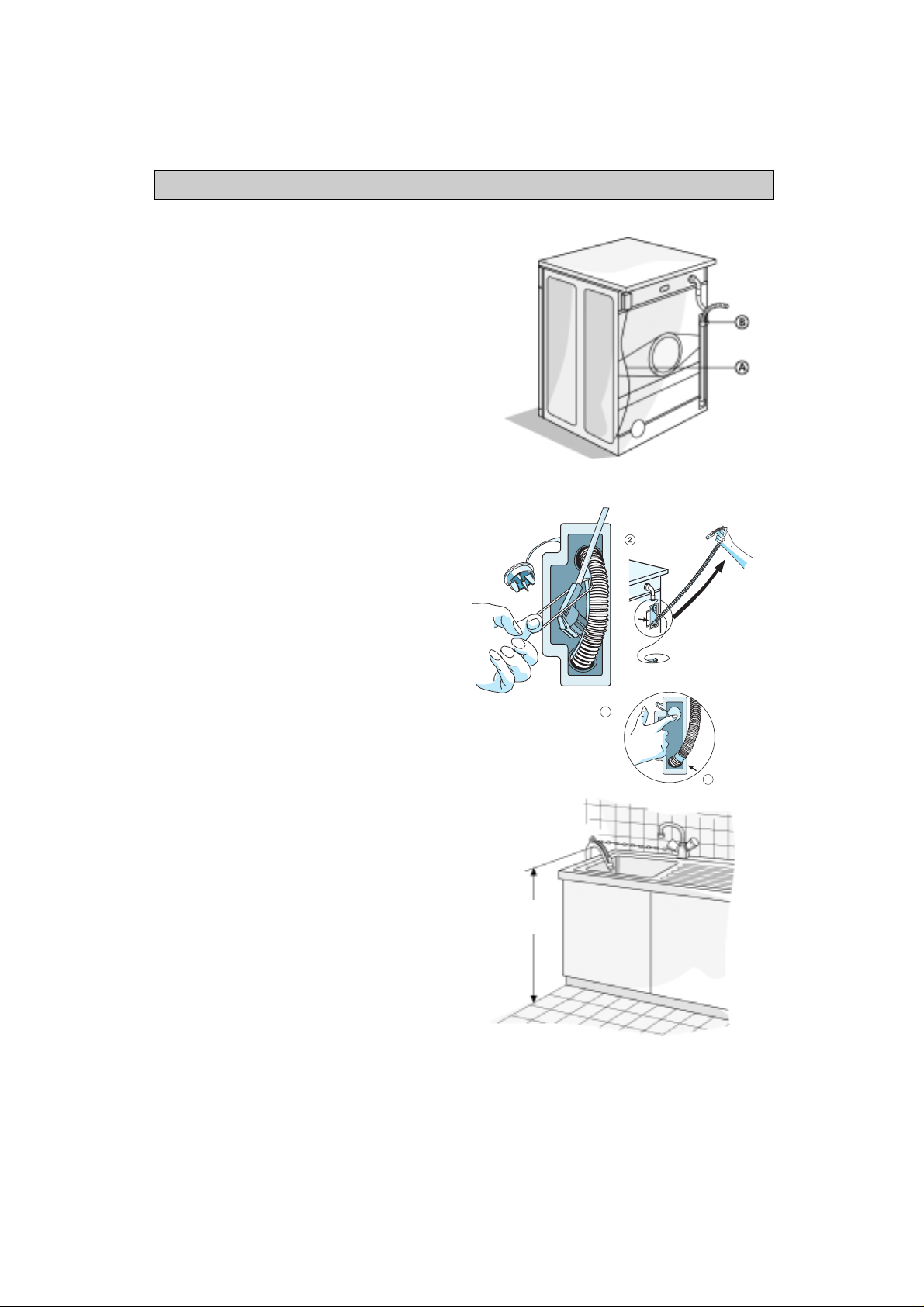
DRAINING
(varies according to model)
a) Drain hose on rear panel of appliance,
Figure 1
Unhook the drain hose from the left clip, see
1.
arrow A in Fig. 1.
Important:
Do NOT loosen the right drain hose
connection, see arrow B in Fig. 1, otherwise
there is the risk of leakage (danger of
scalding with hot water).
b) Appliance internal drain hose , Figure 2
Pull downwards on the loop until the end of the
1.
hose is pulled completely out of the holder.
Pull out the hose upwards until th e mark on the
2.
hose is visible (see Figure 2, arrow in Fig. 3).
Close off the circular opening that is now
3.
exposed using the stopper.
Drain hose connection to water outlet.
•
Fit the drain hose either to the siphon or hook
1.
it over the edge of a sink or bath tub with the
“U” bend (Fig. 2). Small hand basins are not
suitable. The edge of the tub must be no
higher than 125 cm above the floor.
Minimum drain height: 70 cm.
2.
Maximum drain height (“U” bend): 125 cm.
If you need to add an extension, use a
3.
flexible hose of the same type and secure the
union with screw-on hose clips.
Maximum overall drain hose length 2.5 m
Fig. 1
1
Important
Make sure that there are no kinks in the drain
hose run and take precautions against it falling
while the appliance is running (Fig. 3).
CONNECTION TO THE MAINS
Observe local utility company regulations.
•
The connection must be made with a correctly
•
installed, earthed and insulated socket.
The system must be earthed.
•
The manufacturer declines all responsibility
for injury to persons or pets and damage to
property caused by disregarding the above
instructions.
The data concerning voltage, consumption
•
and necessary fuse are supplied on the
inside of the appliance door.
The mains connection cable may only be
•
replaced by a qualified electrician.
The appliance conforms to European safety
•
regulations, EC directive 93/68/EWG and
EN 60555.
Do not use extension leads or multiplugs.
•
Fig. 2
Fig. 3
3
min70 cm
max125 cm
25
 Loading...