

Whirlpool ACM 631 IX Installation Instructions Manual

INSTRUCTIONS FOR USE
INSTALLATION INSTRUCTIONS
BEFORE USING THE APPLIANCE
PRECAUTIONS AND GENERAL ADVICE
ENERGY SAVING TIPS
OVEN ACCESSORIES
CLEANING AND MAINTENANCE
TROUBLESHOOTING GUIDE
AFTER-SALES SERVICE
For best use of the oven, carefully read the operating instructions and keep them for future consultation.
ACM 631 IX

*The max. load that can be placed on the pastry tray is 5kg.
ACM 631 IX
PRODUCT DESCRIPTION SHEET
GB
5019 310 66103
ACCESSORIES (depending on models)
CONTROL PANEL
* The hob control knobs are not interchangeable. After cleaning or servicing, they must be returned to their original positions.
2
4
5
1
3
c
d
e
a
6
OVEN
HOB
a. Rapid burner (front left)
b. Semi-rapid burner (rear left)
c. Semi-rapid burner (rear right)
d. Auxiliary burner (front right)
e. Rear left hotplate
1. Control panel
Grill and upper heating element
Oven light
Lower heating element
Oven door
Lid
2.
3.
4.
5.
6.
Wire shelf: Baking tray:
Turnspit:
1.
Electronic timer
Oven function selector knob
Thermostat indicator lamp
Thermostat knob
Rear left burner control knob
Front left burner control knob
Front right burner control knob
Rear right burner control knob
Hotplate operation control and oven power indicator lamp
Rear left hotplate knob
2.
3.
4.
5.
6.
7.
8.
9.
10.
Max
200°
150°
100°
50°
1
2
3
4
5
6
ACM 631 IX
21 1043 76
89
NB: Cooking times and temperatures are approximate.
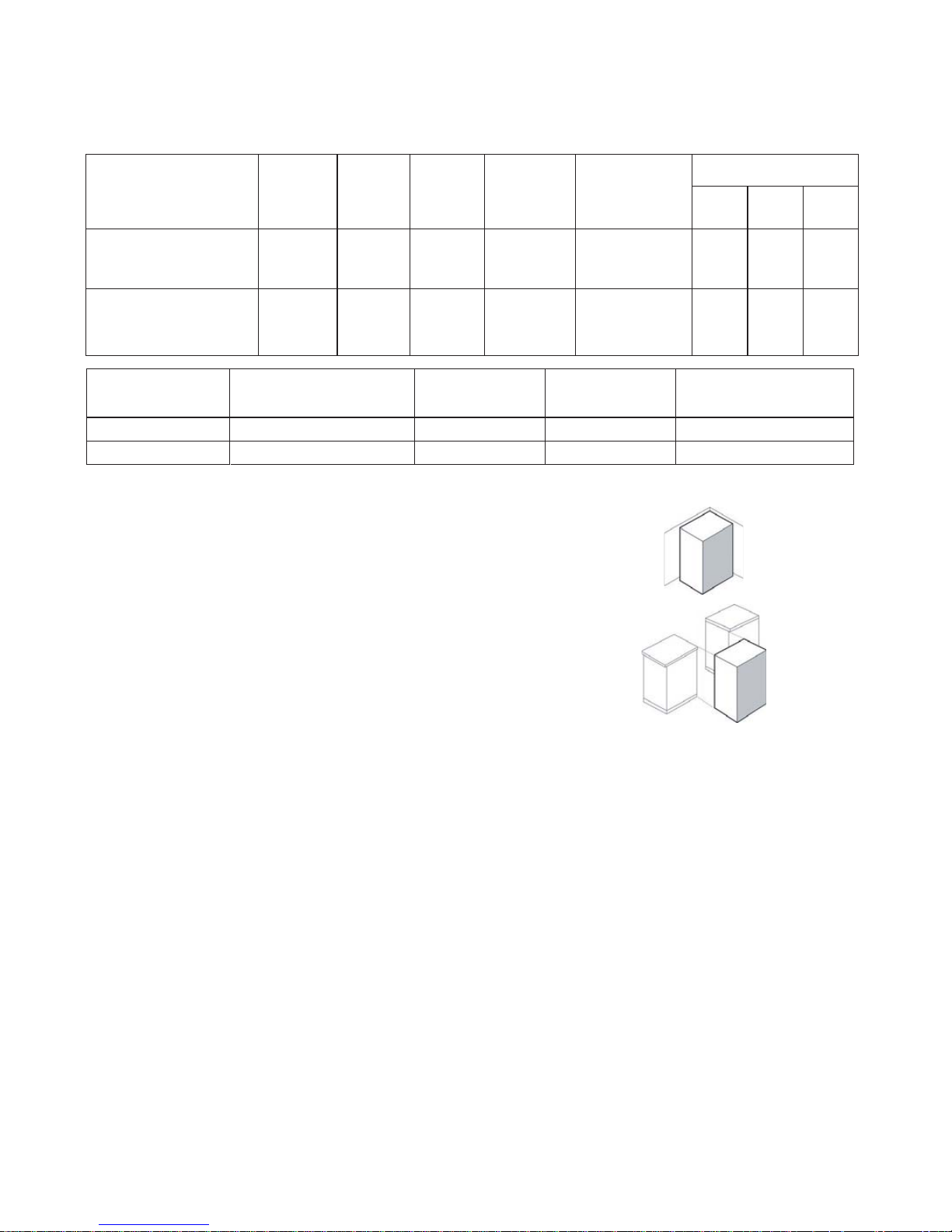
CLASSES OF APPLIANCES
The cooking appliances described on this product sheet belong to the
following installation classes:
• Class 1: non-flush-mounted cooking appliance;
• Class 2 - subclass 1: cooking appliance flush-mounted between two
units, consisting of a single unit, but which can also be installed so that the
side panels are accessible.
Gas pressure mbar
min max.nominal
Type of gas used Total nominal
heating power kW
Appliance model
Total nominal
consumption
Air necessary (m3) for the
combustion of 1 m3 of gas
G20 20 mbar 7.5
665 l/h
9.52
30.94
1R - 2 SR - 1 AUX + oven
ELECTRICAL POWER SUPPLY: 220 V ~ 60 Hz
G30 mbar
1R - 2 SR - 1 AUX + oven 7.5
545 g/h
CATEGORY P/B3H2IIINJECTOR TABLE
Type of gas used
NATURAL GAS
(Methane) G20
rapid
semi-rapid
auxiliary
115
97
72
25
LIQUID PETROLEUM GAS
(Butane) G30
35
rapid
semi-rapid
85
65
3.0
1.75
1.0
236 l/h
167 l/h
95 l/h
0.70
0.495
0.30
3.0
1.75
236 l/h
167 l/h
0.85 0.65
20
17
25
30
Type of
burner
Injector
marking
Injector
marking
Rated
consumption
Reduced heat
capacity kW
INSTALLATION INSTRUCTIONS
Electrical connection
Before connecting the appliance, make sure:
1. the mains voltage in your home matches that specified on the appliance dataplate;
2. the electrical system adequate for appliance max. power absorption specified on the dataplate;
3. the house electrical system is suitably earthed.
•Connect the appliance to the power supply by means of a suitable disconnecting switch with min. contact opening
distance allowing complete disconnection in category III overvoltage conditions, in compliance with the installation
regulations.
Notes: After installation, the electrical components must only be accessible with the use of a special tool. The power
cable must be H05VV-F type, in compliance with the table given below.
Connect a power cable of suitable section:
Instructions for the installer
Warning
•Disconnect the appliance from the power su pply before carrying out any repairs or operation.
•Installation must be carried out by a qualified technician, in compliance with the current safety regulations.
•The appliance must be earthed.
The Manufacturer declines any liability for injury or damage to people or property due to non-compliance with the
above-mentioned regulations. The appliance dataplate is located at the bottom right of frame of the oven cavity and
visible with the door open. Adjustment conditions are given on a label on the packing. Do not use the oven door for
handling operations, or for removing the appliance from the packing.
Type of appliance Single-phase power supply
220V 60 HZ
Gas hob with gas oven
Philippines’s plug and AWG wire AWG 16X 2
1,5mm2 grounding wire
Section 3 x 1 mm²
Gas connection
For information regarding gas connection instructions, see the section
on “standards” relevant to your country (“References to National
Regulations”).
The gas supply system must comply with current local regulations.
The appliance must be connected to the gas supply or gas bottle by
means of a rigid copper or steel pipe with fittings conforming to local
regulations or by means of a continuous s/steel hose conforming to
local regulations.
The hose must not be longer than 2 m.
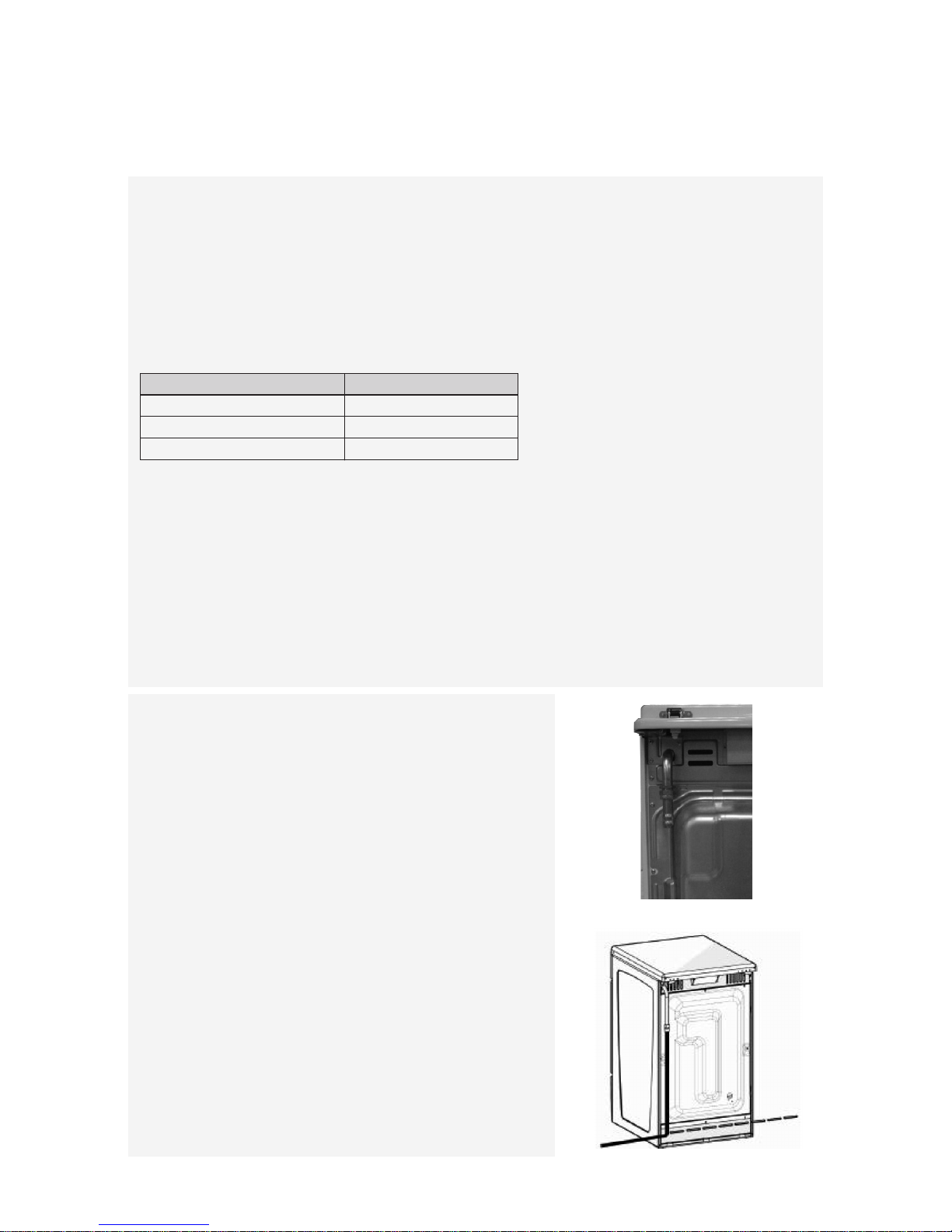
The hose must be connected directly to the elbow of the outlet union
(Fig.1).
Important: When using a hose, it must be installed so that no part of
it is contact with hot parts on the back of the appliance or cooker. Its
path must be free of any hindrances and in a place where it can be
inspected along the entire length (Fig.2).
When the appliance is connected to the gas supply, use soapy
water to check for gas leaks.
This appliance shall be installed in accordance with the regulations
in force and only used in a well ventilated space. Read the
instructions before installing or using this appliance.
Fig. 2
Fig. 1
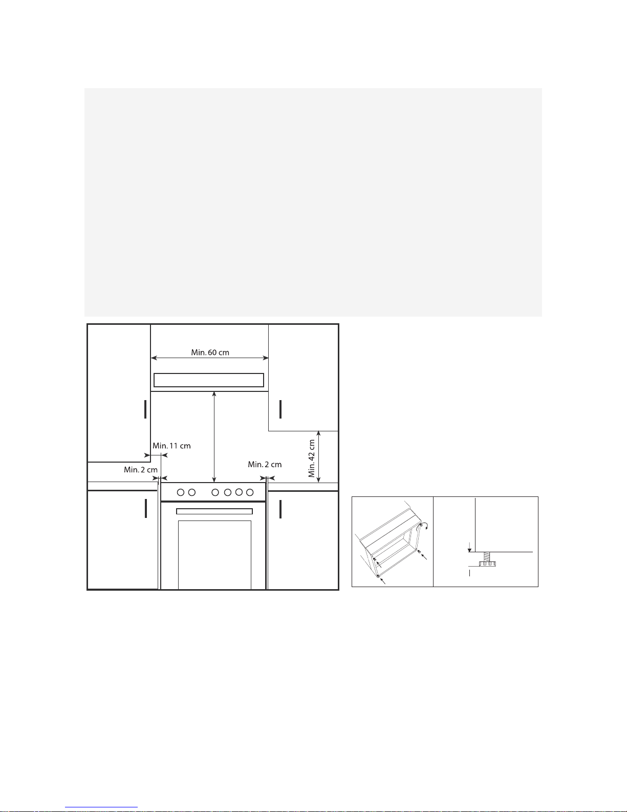
Installation
Important: The covering of the cabinets must be in heat resistant (min. 90°C) material.
If the appliance is installed next to kitchen cabinets, ensure the minimum clearances indicated in the following figure.
There are certain points to pay attention to when positioning the cooker. Make sure to take into consideration the
following recommendations, in order to prevent any problems and hazardous situations that may occur!
The cooker can be positioned near other cabinets provided their height does not exceed the hob level.In selecting a
position for the cooker, make sure the appliance is not placed next to a refrigerator and that there are no flammable or
combustible materials in the vicinity, such as curtains, etc. which can quickly catch fire.
A minimum space of 20 mm between the metal rear cover of the cooker and the wall is required to ensure air
circulation.
If the counter tops are higher than hob level, they should be at least 110 mm from the sides of the cooker.
To fit them, tilt the appliance and screw the 4 feet in the special threads located in the corners (see Fig.2).
Fig. 2
Max.
adjustment
15mm
Fig. 1
Min. 65 cm
Min. 50 cm (depending on the model)
ELECTRICAL CONNECTION AND SAFETY
• The earth wire must be connected to the earth terminal ( ). If there
is no approved earthed electrical outlet in the place where the
appliance is to be installed, immediately contact to our Authorised
Service.
• The earthed electrical outlet must be close to the appliance. Do not
use extension cords.
• The power cable must not touch hot parts of the product.
• If the power cable is damaged, contact a Qualified Service Centre.
The cable must be replaced by the Authorised Service.
• An incorrect electrical connection could damage your appliance. Such
damage is not covered by the warranty.
• The appliance is arranged for a 220 Volt power supply. If the power
supply voltage is different, immediately contact to our authorised
service.
The power cable must not touch hot parts of appliance. Otherwise it may
become damaged.
This situation could cause short circuiting.
The manufacturer declines any liability for damage and loss due to
failure to comply with the following safety regulations
If replacing the power cable, the new one must have the same
characteristics that are specified in this manual.
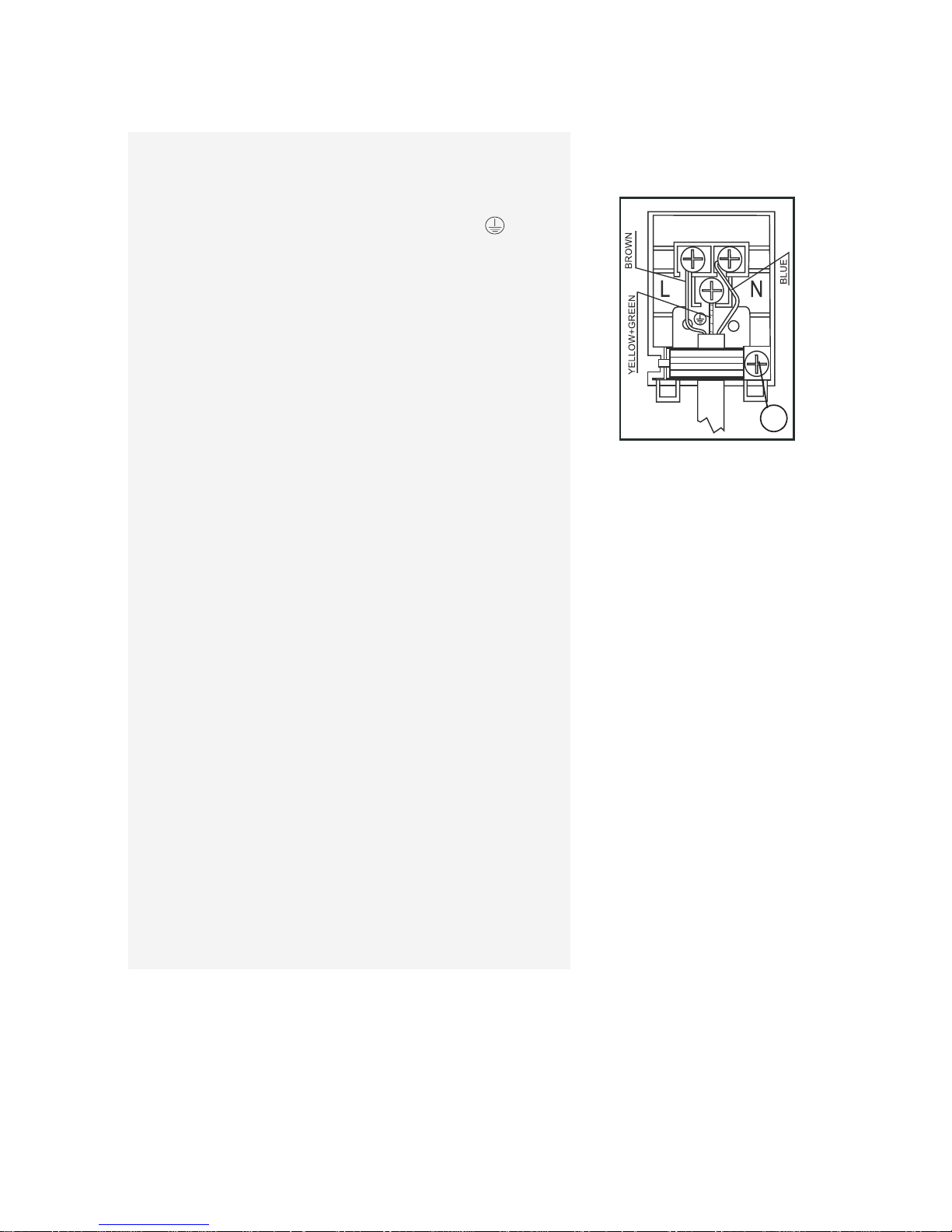
• To replace the cable, proceed as follows:
• open the terminal board box;
• undo the cable fixing screw A;
• loosen the screw contacts and replace the cable with one of the same
length, complying with the table in the section “Electrical connection”;
• the Yellow/Green earth wire must be connected to the terminal and be
approx. 20 mm longer than the line wires;
• the Blue neutral wire must be connected to the terminal marked with
the letter N;
• the live wire must be connected to the terminal marked with the letter
L.
For the electrical connection, make sure to follow the instructions
given below:
A
Electrical Connection Diagram
 Loading...