

Whirlpool ACG 900 IX User Manual

Users
Guide
Installation
& Servicing
NOTE TO INSTALLER: LEAVE THE OWNER’S GUIDE MANUAL WITH THE APPLIANCE.
(Keep For Future Reference)
Model ACG 900 IX
AU
2
RECORD HERE FOR EASY REFERENCE
Model Colour
Serial Number Installation Date
Dealer's Name and Address
GENERAL INFORMATION
Getting to know your new cooker
Thank you for choosing one of our products.
Our cookers are of simple , rational design. They are
constructed to the best standards to ensure good
service and outstanding safety.
Please read this manual carefully; it will pro vide all the
advice needed to allow you to obtain the best results
from the very first day.
ATTENTION:
- Before using the appliance, do not forget to remove the
protecting parts of the appliance.
WHEN YOU CALL FOR SERVICE
When you call for service or order parts for your unit, be
sure to give:
1. MODEL
2. SERIAL NUMBER
3. COLOUR
4. PART NAME and/or description of problem
5. YOUR FULL NAME, ADDRESS , and HOME TELEPHONE
NUMBER and BUSINESS TELEPHONE NUMBER IF
APPROPRIATE.
ENVIRONMENTAL WARNING
Waste packaging
Do not throw the p ac kaging of your appliance into the dustbin,
but pick out the dif f erent materials (f or inst ance f oil, p aperboard,
polystyrene) according to the local rules for rubbish elimination.
This appliance must only be used for the purpose of domestic
cooking.
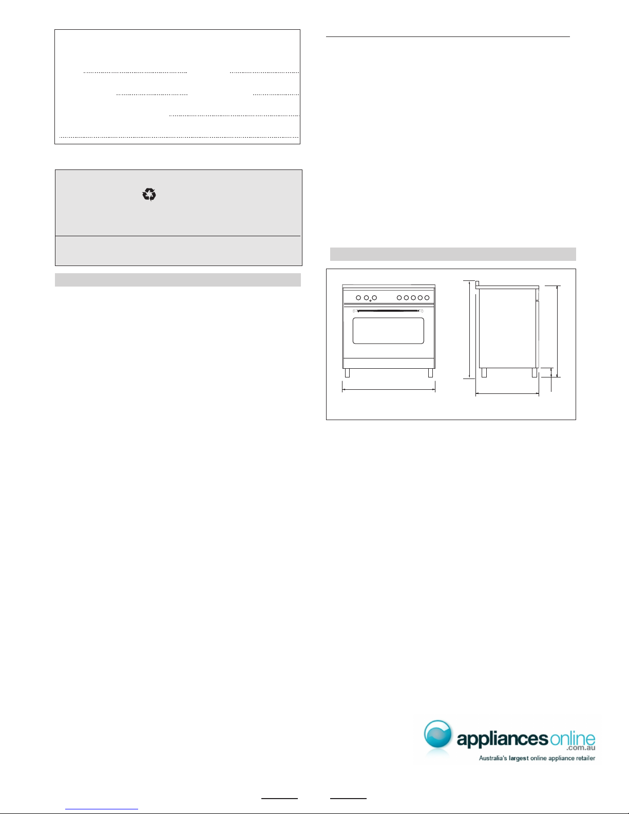
OVERALL DIMENSIONS
SECTION FOR THE QUALIFIED TECHNICIAN
• WARNING -Accessible parts will become hot when in use.
To avoid burns and scalds children should be kept away.
WARNING:
The appliances is not intended for use by children or infirm
persons. Young children and infirm persons should not be left
unsupervised in the vicinity.
WARNING:
If the surface is cracked, switch off the appliance to avoid the
possibility of electric shock.
WARNING:
A steam cleaner is not to be used cleaning this appliances.
WARMING
DO NOT place inflammable materials or plastic utensils in the
warming drawer.
Costumer Service: 1300 363 344
Service call booking: 1300 361 166
Whirlpool Europa S.r.l.
Viale G. Borghi, 27
21025 Comerio (VA) Italy
895
600
h*
950/1000
890/940
h* =
Adjustment
140 / 190
POSITIONING
Important: Fix the chain located next to the gas connection on
both sides of the cooker to the wall to prevent the cooker from
tilting. Both chains must be securely fixed.
Make sure that the wall surface behind the Cooker is noncombustable (will not catch fire).
Where a painted surface is adjacent, a fire ret ardent paint surface
is recommended. Wallpaper, wood, or fabric should not be used
behind or next to the cooker.
“Any adjoining wall surface situated within 200mm from the edge
of any hob burner must be a suitable non-combustible material
for a height of 150mm for the entire length of the hob. Any
combustible construction above the hotplate must be at least
650mm above the maintop.” Ensure that a power and gas supply
are nearby. The Cooker should be located carefully so that the
heat produced by it has plenty of space to escape. The diagram
below shows an ideal configuration.
PROVISION FOR VENTILATION
INSTALLATION
The room where the Cooker is installed should have permanent
ventilation as follows:
“Ventilation must be in accordance with AS5601/AG 601 - Gas
Installations. In general, the appliance should have adequate
ventilation for complete comb ustion of gas, proper flueing and to
maintain temperature of immediate surroundings within saf e limit s .”
- Do not install in a bed-sitting room, a bathroom or sho wer room.
If there is another fuel burning appliance in the same room, a
higher level of ventilation will be required, you should consults
" the safety requirements".
In addition to the abov e , during prolonged use , opening a window
in the same room is recommended. This will avoid the build up
of excessive moisture and condensation.
“If the cooker is being fitted next to cupboards or adjoing wall
surfaces, which are within 200mm from the edge of the hob
burner and of a suitable non-combustible material as specified
in AS5601, ensure that a total gap of at least 12cm is left
between the edge of the cooker”.
This gap could be split equally,
i.e. 6cm on each side, or unequally, to suit circumstances. This
is to allow plenty of space for the heat produced by the hob to
escape at each side of it.
Note:
The cooker is fitted with 4 legs for an ev entual alignment in height
with the furniture ( fig. 1B ).
3
TO FIX THE COOKER TO THE REAR W ALL
WARNING - In order to prevent tipping of the appliance, this
stabilizing means must be installed.
This is required for safety reasons.
The cooker is equipped with 2 chains fixed in the upper part of the
rear right and of the rear left side (see Fig. A - position 1 and 2).
These 2 chains enable to fix the cooker to the rear wall.
To fix the cooker, act as follows:
1. By means of a drill make 2 holes with a diameter of 6mm in the
wall as in Fig. B - position F (with a distance between them as
per Fig. A position 1 and 2).
2. Put in these two holes part. R, then screw part. G (which are
provided with the cooker) (see Fig. C).
3. Bring the cooker near the wall and put the chains on hooks G
as in Fig. D - position C.
Fig. C
wall
R
G
Fig. D
position D
position C
wall
min.100 mm
min. 50 mm
min. 650 mm
min. 400 mm
"0" mm "0" mm
min. 50 mm
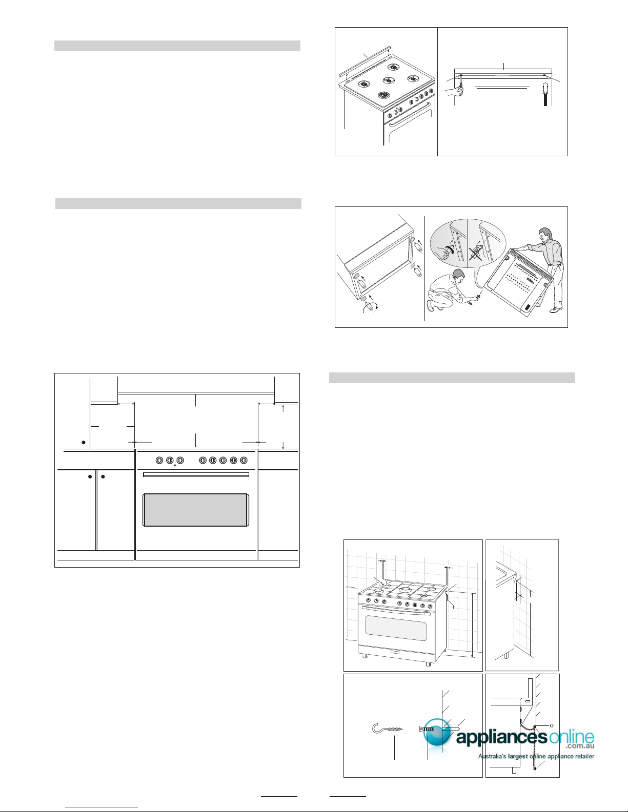
Note:
the cooker is fitted with a metallic rear hob protecting
profile (”F”, see fig. 1) which must be assembled in
following way:
- put the profile (F) on the rear part of the cooker as in fig.
1, and screw the delivered screws (V) as in fig. 1A.
Fig. 1
Fig. 1A
BACK SIDE
V
V
F
86 cm +/- 5
20 mm +/- 3
Position F = Hole
ø 6 mm
OK NO
Fig. B
Fig. 1B
Fig. A
86 cm +/- 5
20 mm +/- 3
20 mm +/- 3
Position
2
Position
1
chain
F
4
SPECIAL NOTE
After installation or any servicing operation, always ensure that
the appliance is gas sound and that the components are now
operating correctly. Items removed during servicing should be
replaced in the reverse order to their removal.
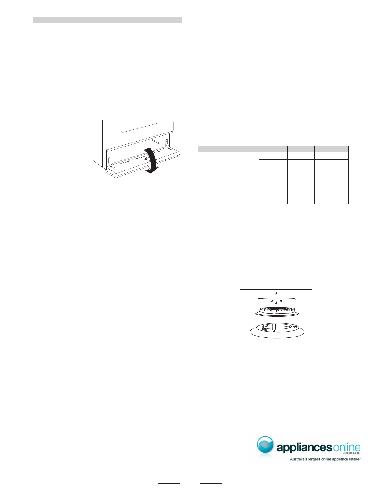
In order to change the work-top injectors, it is necessary to act as
follows:
- remove the grids
- remove burners
and flame-spreaders.
GAS CONNECTION
Should conform to gas utility regulations e.g. AS5601 Gas
installations; also refer to rangehood manufacturers
recommendations.
Check gas pressure, note the correct setting from the data plate
sealed inside the front appliance drawer .
This appliance from the factory suitable for NATURAL gas but, if
necessary, can be adjusted for U-LPG by authorised person.
*
IT IS RECOMMENDED THAT A SERVICE TAP AND UNION BE
FITTED ADJA CENT TO THE APPLIANCE INLET TO FACILITATE
FUTURE SERVICING.
5 burner models: set the burner pressure to 1kPa for Natural Gas
and 2.75kPa for U-LPG with the wok b urner operating a full r ate’.
Apply a manometer to the test nipple and reset the regulator if
necessary. Do not forget to replace the test nipple screw and to
leave the instructions book with the user.
VERY IMPORTANT FOR THE INSTALLER
Do not attempt to turn or stress threaded elbow of the manifold:
you risk damage to this part of the gas appliance which may v oid
the manufacturers warranty.
Before Leaving - Check all connections for gas leaks with soap
and water. DO NOT use a naked flame for detecting leaks. Ignite
all burners to ensure correct operation of gas valves, burners and
ignition. Turn gas taps to low flame position and observe stability
of the flame.
When satisfied with the cooker, please instruct the user on the
correct method of operation.
In case the appliance fails to operate correctly after all checks
have been carried out, refer to the authorised service provider in
your area.’
GAS CONVERSION AND ADJUSTMENT
When used with natural gas all burners have been preset at our
factory and further adjustment should not be necessary. Conv ersion
kits to other gases are available from the place of purchase. Do
not attempt to fit the conversion kit yourself. Conversion to U-LPG
gas should only be carried out by an authorized technician.
GAS ADJUSTEMENTS
- change the injectors
- adjust the minimum flow
‘When converting from Natural Gas to U-LPG ensure that
the NG regulator is removed and replaced with the Test Point
Assembly. A gas regulator suit ab le f or a supply pressure of 2.75kPa
should be part of the gas tank supply and should be adjusted with
the wok burner operating at maximum.
REPLACEMENT OF THE INJECTORS
When required to operate on other gas replace the injectors in
accordance with information referred to in chart below.
other relevant statutory code band regulations. If you have some
doubts, please contact the authorities for confirmation concerning
the characteristics of the gas and electricity output.
The appliance is generally preset for natural gas (so no other
adjustment is necessary) ensure regulator is fitted for N.G.
Ensure that all foreign matter has been cleared from the gas
supply line and also purge all air from the gas system. Connect
to regulator, tighten and check the installation to ensure no gas
leaks occur.
TAB. 1
accordance with the manufacturer’s installation instructions,
relevant local fitting regulations, municipal building regulations,
the AS5601 code for gas burning appliances and equipment and
and 695mm from the floor (depends on adjustment of feet).
The appliance shall be installed by an authorized person in
For the adjustments to U-LPG please operate as specified in the
paragraph GAS CONVERSION AND ADJUSTMENT (pag 4).
The Gas Connection is male 1/2" BSP and is situated at the right
hand rear of the appliance, approximately 40mm from the side
This appliance can be connected with rigid pipe as specified in
AS5601 table 3.1 or with a Plumbezy Flexible hose, AGA Approval
number 6196, 10mm ID, class D and between 1-1.2m long in
accordance with AS5601 for a 'high level connection'.
If connected with a flexible hose, the restraining chain supplied
fitted to each side of the cooker must be fixed to the wall as follows:
1. Drill 2 holes in the wall approximately 100mm up from the floor
to line up with the holes in position 1 & 2 above (see fig. A)
2. Insert part R (above) in each hole and screw in part G into each
part R (fig. C).
3. Fix the chain to part G
at position D (chain
should also be fixed at
position C to prevent
cooker tilting) as shown
in Fig. D. Ensure that the
chain prevents stress on
the hose assembly when
the cooker is moved out
of its normal operating
position.
Natural Gas 1.00 kPa
0.90 Auxiliary 4.0
1.20 Semi-rapid
7.1
1.50 Rapid 11.0
1.60 Wok 12.5
U - LPG 2.75 kPa
0.53 Auxiliary 3.7
0.73 Semi-rapid 7.0
0.95 Rapid 11.7
1.00 Wok 12.9
Jet mm Ø Burners Power MJ/h
Gas Type
kPa
5
- change the injector (see Fig. 1A) and replace it with another
one suitable for the new type of gas (see tab. 1)
Fig. 1A
Z
Fig. 2BFig. 2A
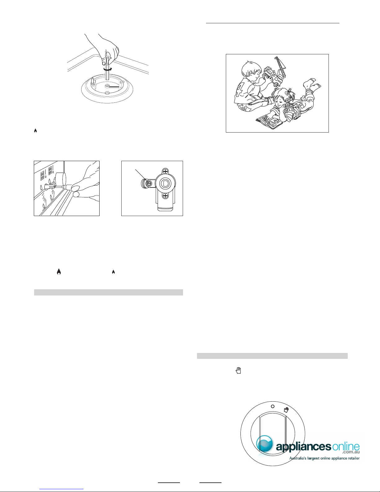
MINIMUM FLOW ADJUSTMENT FOR HOB-TOP TAPS
In order to adjust the minimum flame setting proceed as follows:
switch the burner on, and set the knob at the minimum position
. Remove the knob from the t ap, place a small bladed screwdriver
down the centre of the tap shaft (fig. 2A).
Attention: on taps with a security valve, the minimum adjusting
screw «Z» is on the body of the gas tap (fig. 2B).
Unscrew the adjusting scre w in order to increase the flow or scre w
it to decrease the flow.
The correct adjustment is obtained when the flame has a length
of about 3 or 4 mm.
For butane/propane gas, the adjusting screw must be screwed
in thigt.
Make sure that the flame does not go out turning quickly from the
max. flow to the minimum flow .
Refit the knob again.
ELECTRICAL CONNECTION
‘In order to avoid hazard, any electrical work performed on this
equipment or its associated wiring, should only be done by persons
authorised by the supplier or similarly qualified persons.’
2nd SECTION FOR THE USER
WARNING:
Children should be kept away while the oven or grill is in use
since accessible parts become hot.
- Do not use oven base panel as a shelf, make use of the oven
shelves.
- To avoid splattering and smoke, position collecting tray under
the grill with some water in it.
- Always turn pan handles to the side or to the back of the hob.
If they are left out into the room they can easily be hit or reached
by children, this knocking the pan off the hob.
- Don’t let children sit down or play with the oven door. Do not
use the drop down door as a stool to reach above cabinets.
- Once your cooking is over make sure to close the main gas
supply.
WARNING
* This appliance is not intended for use by young children or
infirm persons without supervision.
* Young children should be supervised to ensure that they do
not play with the appliance.
WARNING
Before you use the appliance for the first time, check that the
plastic films protecting some parts (fascia panel, parts in stainless
steel, etc.) have been removed.
WARNING - In order to prevent accidental tipping of the appliance,
for example by a child climbing onto the open oven door, the
stabilizing means must be installed.
DO NOT SPRAY AEROSOLS IN THE VICINITY OF THIS APPLIANCE
WHILE IT IS IN OPERATION.
Electric..................1.5mm2 3 core cable (15 amp fuse required)
WARNING: THIS APPLIANCE MUST BE EARTHED
Connecting the mains cable
Open the mains terminal block co v er as sho wn, unscre w the cable
clamp «A» and unscrew (not fully) the scre ws in the mains terminal
block «L N E» which secure the three wires of the mains cable.
Fit the cable and refit the cable clamp «A» (fig. 10) .
IMPORTANT
The wires in the mains lead are coloured in accordance with the
following code:
GREEN & YELLOW.........................................................EARTH
BLUE...........................................................................NEUTRAL
BROWN ...............................................................................LIVE
The supply cable must not come into contact with any component
the temperature of which exceeds the ambient temperature by
50°C.
Easy access to the plug or the switch is ensured once the appliance
is installed.
Ensure that there is sufficient cable allowed for any subsequent
removal of the unit.
PROGRAMMER WITH COOKING END TIME
For a manual operation of the programmer, turn the knob
anticlockwise to .
Adjust the cooking time by turning the knob clockwise.
Select the cooking time with the relevant knob (max.120 min.).
The oven will switch off automatically when the cooking is up.
0
10
20
30
40
50
60
70
80
90
100
110
120
stop
BURNERS PANS
fl min. fl max
AUXILIARY 80 mm 160 mm
SEMI-RAPID 120 mm 200 mm
RAPIDE 200 mm 230 mm
TRIPLE CROWN 230 mm 260 mm
- 1 Minute Tour -
Be safe
Please read the rest of the instruction book which contains
important information to help you use the appliance safely and
efficiently.
Gas and Electricity on
Make sure that the gas supply is turned on and that the appliance
is plugged in and switched on. The ignitor needs electricity.
In case there is no electric current, the burner can also be lighted
using a match.
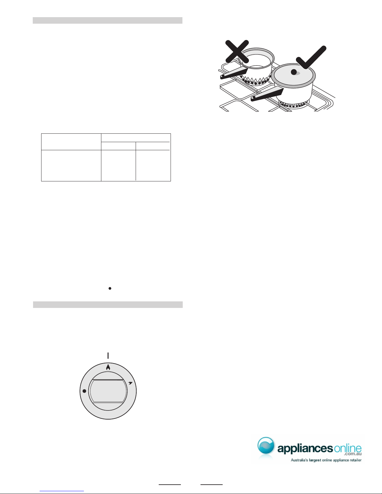
It is recommended that pans suitable to the size of the burner
should be used as follows:
6
The small flame indicates the ‘low position’.
Turn the knob to it after the contents of a pan have boiled.
The smaller burners are for smaller pans and simmering. Make
sure flames are under the pans. Using a lid will help the contents
boil more quickly.
Always use pans with a flat base diameter, which are well balanced
and stable in use, a pan which overhangs the hotplate should not
be used. Avoid using old, misshapen pans, or pans which are
unstable when placed on a flat surface. Do not use “split pans”
as they are inherently unstable.
To save gas, always position pans centrally over the burners and
adjust the flames so that they do not lick up the sides of the pan
and only the base is heated. Always put lids on saucepans and
boil only the amount of liquid you use. When the liquid has boiled
adjust the setting to maintain a simmer. Do not light the burner
until the pan is in position and turn off the burner before removing
the pan. In hard water areas, descale kettles regularly. For safety,
keep saucepan handles turned to a safe position so they are out
of reach of small children and cannot be accidentally knocked.
To tunr the burner OFF, turn the control knob clockwise to the
OFF setting (marked with a dot )
WARNING
It is not recommended to press push button for ignition if all the
burners are not located in the proper positions. The burner heads,
burner skirts and pan supports are removable for better cleaning:
Always ensure that the burner skirts and heads are replaced
correctly so that the burners function safely and correctly.
During the use of the appliance pay attention that water or any
liquid does not enter into the appliance through the holes of the
burners or around the rods of the valves or the push button
electronic lighter.
Water or juice will produce dangerous short-circuits and can
seriously damage the working of the Hotplate.
Automatic electric ignition
To turn on a burner, press the knob corresponding to the
selected burner and turn it anticlockwise to the maximum
position. Keeping the knob pressed, the electric automatic
ignition of the burner will be started up. In case there is not
electric current, the burner can also be lighted using a
match.
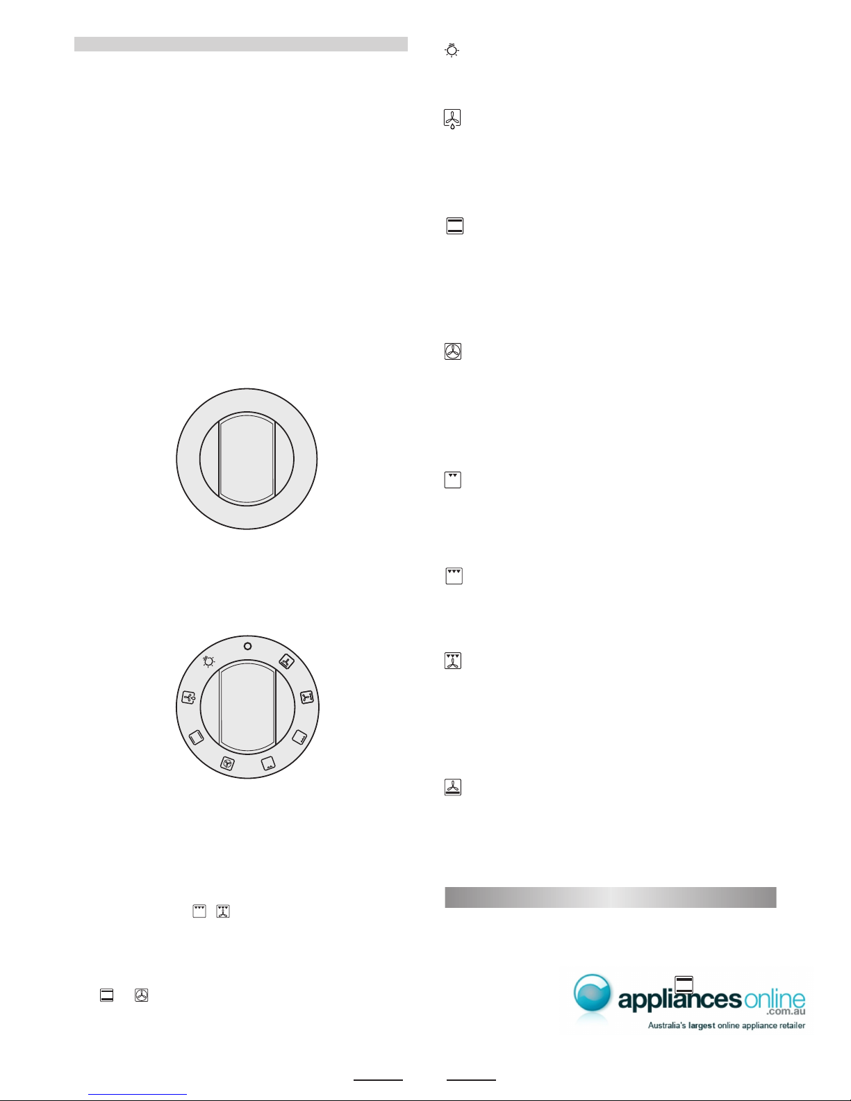
Oven commutator knob
Depending on the type of oven, it is possible to select one of the
following functions turning the commutator knob clockwise.
Note:
All the functions mentioned above switch the oven internal light on.
A warning light on the control panel will stay lit until the temperature
is reached; after it will light up intermittently.
Always use the oven with the oven door closed.
Use of the oven
Note: ovens with separate thermostat and commutator.
When the functions are used, place the thermostat
knob between 180 ÷ 200°C as maximum temperature.
ATTENTION:
The temperature shown on the control panel corresponds to the
temperature in the oven centre only when the functions selected
are or .
GENERAL INSTRUCTION
Warning: remember ovens get hot; some parts naturally become
very hot, notably the glass oven door and the protective strip.
Keep children away from oven at all times and warn them about
the danger.
GUIDE FOR CONVENTIONAL COOKING
(Outer ring of upper electric element and lower electric element
ON) The following Cooking Guides give the recommended shelf
positions (counted from the bottom), thermostat settings and
approximate cooking times for a range of baked items, using the
MULTIFUNCTIONAL OVEN
The oven is fitted with:
• a lower heating element;
• an upper heating element;
• a circular heating element surrounding the fan.
N.B.: Always set the temperature on the thermostat knob before
selecting any of the functions.
Oven thermostat knob
To obtain an oven temperature between 60°C and MAX°C, turn the
knob clockwise.
HOW TO USE YOUR ELECTRIC OVEN
- Before cooking in the first time we reccommend that the oven
should be operated at 200° C for 30 minutes to remove any
manufacturing greases and odours.
- Do not place items or pan directly on to the oven botton.
- Foil should only be used to cover food and not oven shelves or
party of the oven. When used improperly will obstruct the air
circulation causing problems in cooking and/or harmful accidents.
7
60
80
100
125
150
175
200
225
max
Natural convection
Both the lower and upper heating elements operate together.
This is the traditional cooking, very good for roasting joints, ideal
for biscuits, baked apples and crisping food.
You obtain very good results when cooking on a shelf adjusting
the temperature between 60 and MAX°C.
Fan oven
Both the fan and the circular heating element operate together.
The hot air adjustable between 60 and MAX°C is evenly distributed
inside the oven. This is ideal for cooking several types of food
(meat, fish) at the same time without affecting taste and smell.
It is indicated for delicate pastries.
Medium grill
It is indicated for grilling and gratinating small quantities of traditional
food.
The thermostat knob must be placed on the maximum position.
Total grill
It is indicated for grilling and gratinating traditional food.
Turn the thermostat control knob to the 200°C position.
Fan assisted total grill
The air which is heated by the grill heating element is circulated
by the fan which distributes the heat on the food.
The fan assisted grill replaces perfectly the turnspit. Y ou can obt ain
very good results also with large quantities of poultry, sausage,
red meat. Turn the thermostat control knob to the 200°C position.
Air forced lower heating element
The air which is heated by the lower heating element is circulated
by the fan which distributes the heat on the food.
This function can be used to sterilize food. This function can be
used between 60 and MAX°C
When you turn the control knob to this position, the light will be
on for all the following operations.
Defrosting with fan
The air at ambient temperature is distributed inside the oven for
defrosting food very quickly and without proteins adulterations.
conventional oven, using one tray only. Cooking results are a
matter of personal preference and may easily be adjusted to suit
individual requirements by slight adjustment of the temperature
and or cooking time. Preheating of the oven is recommended for
10-15 minutes or until the oven thermostat indicator light switches
off to show the selected temperature has been reached.
When using a baking tray it should be placed centrally on the oven
shelf with the short sides of the tray parallel to the sides of the
oven. Do not use trays, tins or dishes larger than 380 mm (15")
long, 356 mm (14") wide, as cooking results may be impaired.
PLATE WARMING
Ovenproof plates and dishes may be warmed in the oven on a
low temperature setting. Remember do not place items directly
into the oven base.
Warning: do not use foil to cover the oven shelves, or any part
of the oven interior including the oven base. Foil should only be
used to cover food and cooking dishes. Always place items which
may boil over (e.g. fruit pies) on a baking tray to prevent spillage
burning onto the oven base. Foil used improperly is frequent
cause of oven problems and painful accidents. A void letting grease
deposit collect around the upper heating element: it will cause
smoking and may start a fire.
Remember do not place pan or items directly onto the oven base.
Never leave unit unattended at hight heat settings. Boil over
causes smokingand greasy spill over that may start a fire.
If a grease fire should occur in a pan put out the flame by placing
a lid on the pan. Do not throw water on a grease fire.
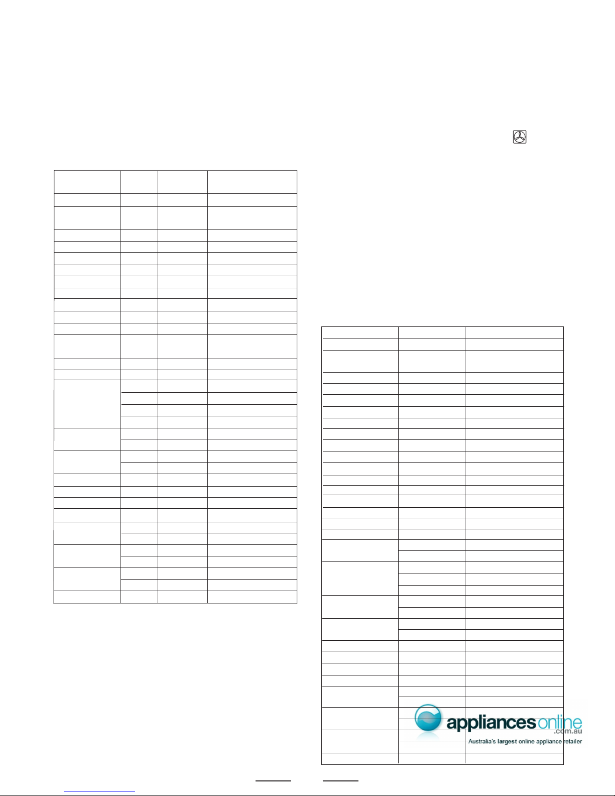
GUIDE FOR FORCED CONVECTION COOKING
(Back rolled electric element with fan)
The accessories provided with the oven can be slotted in at 5
positions: the following guide concerns cooking times and thermostat
settings using N. 2 shelves on the same time (in position N. 2 and
N. 4). Cooked results are a matter of personal preference and may
easily be adjusted to suit individual requirements by slight adjustment
of the temperature and/or cooking time, or when using more or
less shelves in the same time. Preheating of the oven is
recommended for 10-15 minutes or until the oven thermostat
indicator light switches off to show the selected temperature has
been reached.
When using a baking tray it should be placed centrally on the oven
shelf with the short sides of the tray parallel to the sides of the
oven. Do not use trays, tins or dishes larger than 380mm (15")
long, 356 mm (14") wide, as cooking results may be impaired.
Food Thermostat Shelf Position Cooking Time
setting °C
(Counted from Bottom)
Small cakes (12 on tray) 195 3 20 - 30 mins.
Victoria sandwich 190 3 25 - 35 mins.
(2x7"/180mm)
Swiss roll or whisked sponge 200 3 20 - 25 mins.
Fruit cake (8"/205mm) 155 2 2 - 3 hours.
Scones 260 3 10 - 20 mins.
Meringues 95 2 2 - 3 hours.
Shortcrust Pastry 210 3 25 - 45 mins. depending
Puff or Flaky Pastry 220 2 20 - 35 mins. upon
Choux Pastry 220 3 25 - 35 mins. dish
Biscuits 200/220 3 15 - 25 mins. depending upon type
Bread 250 2 30 - 40 mins.
Milk pudding 165 2 1 H - 2 hours.
Pizza 270 3 25 mins.
Lasagne 170 3 75 mins.
Oven noodles 160 3 75 mins.
BEEF on bone & crusty 270 rare 3 12 mins. per 1/b (500 g) plus 12 mins.
(rare) 220 °C 3 15 mins. per 1/b (500 g) plus 15 mins.
(medium) 220 °C 3 20 mins. per 1/b (500 g) plus 20 mins.
(well done) 180 °C 3 25 mins. per 1/b (500 g) plus 15 mins.
LAMB on bone 220 °C 3 20 mins. per 1/b (500 g) plus 20 mins.
170 °C 3 27 mins. per 1/b (500 g) plus 27 mins.
Boned and rolled 220 °C 3 25 mins. per 1/b (500 g) plus 25 mins.
170 °C 3 35 mins. per 1/b (500 g) plus 20 mins.
PORK on bone 220 °C 3 25 mins. per 1/b (500 g) plus 25 mins.
Boned and roller 180 °C 3 30-35 mins. per 1/b (500 g) plus 35 mins.
VEAL on bone 220 °C 3 25 mins. per 1/b (500 g) plus 25 mins.
Boned and roller 220 °C 3 30 mins. per 1/b (500 g) plus 30 mins.
CHICKEN 220 °C 3 20 mins. per 1/b (500 g) plus 20 mins.
170 °C 3 25 mins. per 1/b (500 g) plus 25 mins.
TURKEY 220 °C 3 20 mins. per 1/b (500 g)
170 °C 3 25 mins. per 1/b (500 g)
DUCK 220 °C 3 20 mins. per 1/b (500 g)
170 °C 3 25 mins. per 1/b (500 g)
GOOSE 220 °C 3 20 mins. per 1/b (500 g) plus 20
Food Thermostat setting °C Cooking Time
Small cakes (12 on tray) 175 15-25 mins.
Victoria sandwich 170 20-30 mins.
(2x7"/180mm)
Swiss roll or whisked sponge 180 15-20 mins.
Fruit cake (8"/205mm) 135 1 H - 2 H hours.
Scones 210 8-15 mins.
Meringues 80 1 H - 2 H hours.
Shortcrust Pastry 190 20-40 mins. depending
Puff or Flaky Pastry 200 15-30 mins. upon
Choux Pastry 200 20-30 mins. dish
Biscuits 170/180 10-20 mins. depending upon type
Bread 200/220 25-35 mins.
Milk pudding 150 1 H - 2 hours.
Pizza 250 20 mins.
Lasagne 165 60 mins.
Oven noodles 150 60 mins.
BEEF on bone 230 rare & crusty 9 mins. per 1/b (500 g) plus 9 mins.
BEEF on bone 190 °C (rare) 15 mins. per 1/b (500 g) plus 8 mins.
190 °C (medium) 20 mins. per 1/b (500 g) plus 10 mins.
160 °C (well done) 25 mins. per 1/b (500 g) plus 8 mins.
Boned and rolled 190 °C (rare) 20 mins. per 1/b (500 g) plus 10 mins.
190 °C (medium) 25 mins. per 1/b (500 g) plus 15 mins.
160 °C (well done) 30 mins. per 1/b (500 g) plus 8 mins.
LAMB on bone 190 °C 20 mins. per 1/b (500 g) plus 10 mins.
155 °C 27 mins. per 1/b (500 g) plus 14 mins.
Boned and rolled 190 °C 25 mins. per 1/b (500 g) plus 14 mins.
155 °C 25 mins. per 1/b (500 g) plus 14 mins.
PORK on bone 200 °C 25 mins. per 1/b (500 g) plus 14 mins.
Boned and roller 160 °C 30-35 mins. per 1/b (500 g) plus 18 mins.
VEAL on bone 200 °C 25 mins. per 1/b (500 g) plus 14 mins.
Boned and roller 200 °C 30 mins. per 1/b (500 g) plus 14 mins.
CHICKEN 200 °C 20 mins. per 1/b (500 g) plus 10 mins.
155 °C 25 mins. per 1/b (500 g) plus 13 mins.
TURKEY 200 °C 18 mins. per 1/b (500 g) plus 14 mins.
155 °C 23 mins. per 1/b (500 g)
DUCK 200 °C 18 mins. per 1/b (500 g)
155 °C 23 mins. per 1/b (500 g)
GOOSE 180 °C 18 mins. per 1/b (500 g) plus 20 mins.
8
 Loading...