

Whirlpool ACE119PR0 Owner’s Manual
WhJol °
THROUGH-THE-WALL
AIRCONDITIONER
For questions about features, operation/perlormance, parts,
accessories or service call: 1-800-253-1301.
In Canada, call for assistance 1-800-461-5681, for installation
and service, call: 1-800-807-6777
or visit our website at... www.whirlpool.com
or...www.whirlpoolappliances.ca
CLIMATISEUR
ENCASTREDANS
LEMUR
819041994/1188177
Au Canada, pour assistance composez me: 1-800-461-5681, pour
installation ou service, le : 1-800-807-6777
ou visitez notre site web &... www.whirlpoolappliances.ca
Table of Contents/Table des matieres ................ 2
TABLEOFCONTENTS
AIR CONDITIONER SAFETY ......................................................... 2
INSTALLATION REQUIREMENTS ................................................ 3
Tools and Parts ............................................................................ 3
Location Requirements ................................................................ 4
Electrical Requirements ............................................................... 4
INSTALLATION INSTRUCTIONS .................................................. 5
Unpack the Air Conditioner .......................................................... 5
Before Installing Air Conditioner .................................................. 5
Install Air Conditioner in Existing Wall Sleeve ............................. 5
Plastic Grille Installation ............................................................... 6
Install Air Conditioner in New Wall Sleeve ................................... 7
Complete Installation ................................................................... 8
TABLEDESMATIERES
SECURIT¢: DU CLIMATISEUR .................................................... 17
EXIGENCES D'INSTALLATION ................................................... 18
Outillage et pi_ces ...................................................................... 18
Exigences d'emplacement ......................................................... 19
Specifications electriques .......................................................... 19
INSTRUCTIONS D'INSTALLATION ............................................ 20
Deballage du climatiseur ............................................................ 20
Avant I'installation du climatiseur .............................................. 20
Installation du climatiseur dans une gaine murale existante.....20
Installation de la grille de plastique ............................................ 21
Installation du climatiseur dans une nouvelle gaine murale ...... 22
Achever I'installation .................................................................. 23
AIR CONDITIONER USE ................................................................ 9
Starting Your Air Conditioner ....................................................... 9
Changing Air Direction ............................................................... 12
Normal Sounds ........................................................................... 12
AIR CONDITIONER CARE ........................................................... 12
Cleaning the Air Filter ................................................................. 12
Cleaning the Front Panel ............................................................ 13
Annual Maintenance ................................................................... 13
TROUBLESHOOTING .................................................................. 13
ASSISTANCE OR SERVICE ......................................................... 14
In the U.S.A................................................................................ 14
In Canada ................................................................................... 14
WARRANTY .................................................................................. 15
UTILISATION DU CLIMATISEUR ................................................ 24
Mise en marche du olimatiseur .................................................. 24
Changement de direction de I'air ............................................... 27
Sons normaux ............................................................................ 27
ENTRETIEN DU CLIMATISEUR .................................................. 27
Nettoyage du filtre h air .............................................................. 27
Nettoyage du panneau avant ..................................................... 28
Entretien annuel .......................................................................... 28
Dr!:PANNAGE ................................................................................. 28
ASSISTANCE OU SERVICE ......................................................... 30
Au Canada .................................................................................. 30
GARANTIE ..................................................................................... 31
AIRCONDITIONERSAFETY
Your safety and the safety of others are very important.
We have provided many important safety messages in this manual and on your appliance. Always read and obey all
safety messages.
This symbol alerts you to potential hazards that can kill or hurt you and others.
All safety messages will follow the safety alert symbol and either the word "DANGER" or
This is the safety alert symbol.
"WARNING." These words mean:
You can be killed or seriously injured if you don't
immediately follow instructions.
You can be killed or seriously injured if you don't
follow instructions.
All safety messages will tell you what the potential hazard is, tell you how to reduce the chance of injury, and tell you
what can happen if the instructions are not followed.
IMPORTANT SAFETY INSTRUCTIONS
WARN ING: To reduce the risk of fire, electrical shock or injury when using your air conditioner, follow these basic precautions:
• Plug into a grounded 3 prong outlet.
[] Do not use an extension cord.
[] Do not remove ground prong.
[] Do not use an adapter.
[] Unplug air conditioner before servicing.
[] Use two or more people to move and install air conditioner.
SAVE TH ESE INSTRUCTIONS
INSTALLATIONREQUIREMENTS
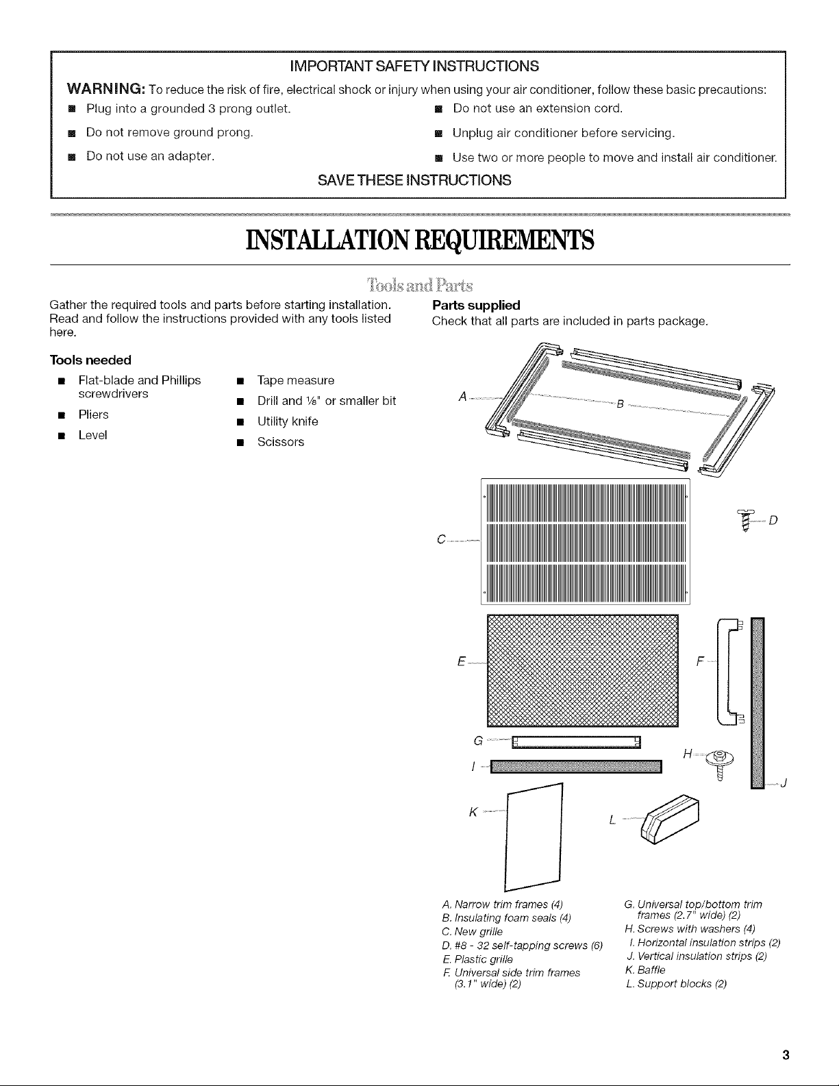
Gather the required tools and parts before starting installation. Parts supplied
Read and follow the instructions provided with any tools listed Check that all parts are included in parts package.
here.
Tools needed
• Flat-blade and Phillips • Tape measure
screwdrivers
• Pliers
• Level
• Drill and 1/s"or smaller bit
• Utility knife
• Scissors
C .........................
G .......
A. Narrow trim frames (4)
B. Insulating foam seals (4)
C. New grille
D. #8 - 32 self-tapping screws (6)
E.Plastic grille
E Universal side trim frames
(3.!" wide) (2)
G. Universal top/bottom trim
frames (2.7" wide) (2)
H. Screws with washers (4)
I. Horizontal insulation strips (2)
J. Vertical insulation strips (2)
K. Baffle
L. Support blocks (2)
Power supply cord Wiring requirements
IMPORTANT: Observe all governing codes and ordinances.
Check the location where the air conditioner will be installed.
Proper installation is your responsibility. Make sure you have
everything necessary for correct installation.
The location should provide:
• Grounded electrical outlet within 4 ft (122 cm) of where the
power cord exits the air conditioner.
NOTE: Do not use an extension cord.
• Free movement of air in room to be cooled.
• A large enough opening for the air conditioner and sleeve
(sold separately).
• Adequate wall support for weight of air conditioner.
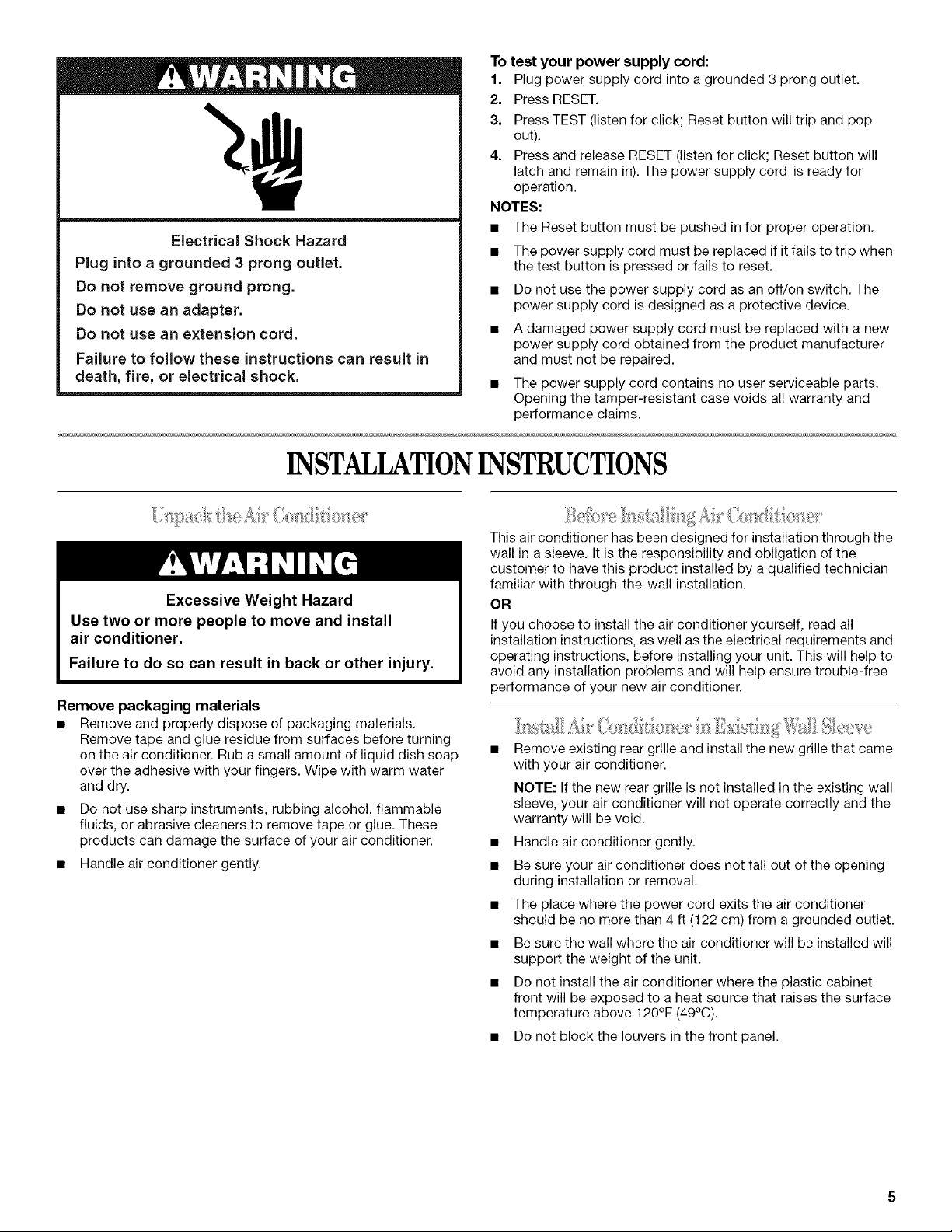
Electrical Shock Hazard
Plug into a grounded 3 prong outlet.
Do not remove ground prong.
Do not use an adapter.
Do not use an extension cord.
Failure to follow these instructions can result in
death, fire, or electrical shock.
The electrical ratings for your air conditioner are listed on the
model and serial number label. The model and serial number
label is located behind the front panel on the front flange above
the coil area.
Specific electrical requirements are listed in the chart below.
Follow the requirements for the type of plug on the power supply
cord.
• 115-volt (103.5 min. -
126.5 max.)
• 7.6-12 amps
• 15-amp time-delay fuse or
circuit breaker
• Use on single outlet circuit only.
• 230/208 volt (197.6 min. -
1/4" 253 max.)
(0,6cm)
• 15-amp time-delay fuse or
_ • 0-12 amps
circuit breaker
• Use on single outlet circuit only.
Recommended ground method
This air conditioner must be grounded. This air conditioner is
equipped with a power supply cord having a grounded 3 prong
plug. To minimize possible shock hazard, the cord must be
plugged into a mating, grounded 3 prong outlet, grounded in
accordance with all local codes and ordinances. If a mating outlet
is not available, it is the customer's responsibility to have a
properly grounded 3 prong outlet installed by a qualified electrical
installer.
It is the customer's responsibility:
• To contact a qualified electrical installer.
• To assure that the electrical installation is adequate and in
conformance with National Electrical Code, ANSI/NFPA 70 -
latest edition, and all local codes and ordinances.
Copies of the standards listed may be obtained from:
National Fire Protection Association
One Batterymarch Park
Quincy, MA 02269
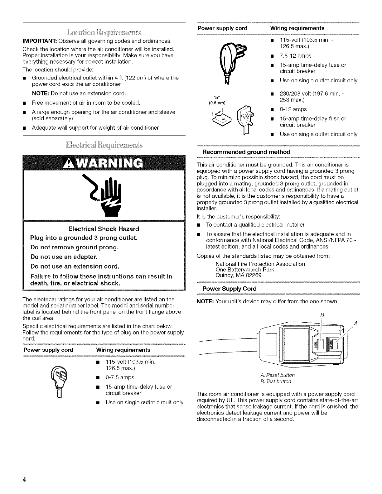
Power Supply Cord
NOTE: Your unit's device may differ from the one shown.
B
,i
Power supply cord Wiring requirements
• 115-volt (103.5 min. -
• 0-7.5amps
• 15-amp time-delay fuse or
126.5 max.)
circuit breaker
• Use on single outlet circuit only.
A. Reset button
B. Test button
This room air conditioner is equipped with a power supply cord
required by UL. This power supply cord contains state-of-the-art
electronics that sense leakage current. If the cord is crushed, the
electronics detect leakage current and power will be
disconnected in a fraction of a second.
Electrical Shock Hazard
Plug into a grounded 3 prong outlet.
Do not remove ground prong.
Do not use an adapter.
Do not use an extension cord.
Failure to follow these instructions can result in
death, fire, or eJectricaJ shock.
INSTALLATIONINSTRUCTIONS
,, [ i
To test your power supply cord:
1. Plug power supply cord into a grounded 3 prong outlet.
2. Press RESET.
3. Press TEST (listen for click; Reset button will trip and pop
out).
4. Press and release RESET (listen for click; Reset button will
latch and remain in). The power supply cord is ready for
operation.
NOTES:
• The Reset button must be pushed in for proper operation.
• The power supply cord must be replaced if it fails to trip when
the test button is pressed or fails to reset.
• Do not use the power supply cord as an off/on switch. The
power supply cord is designed as a protective device.
• A damaged power supply cord must be replaced with a new
power supply cord obtained from the product manufacturer
and must not be repaired.
• The power supply cord contains no user serviceable parts.
Opening the tamper-resistant case voids all warranty and
performance claims.
Excessive Weight Hazard
Use two or more people to move and install
air conditioner.
Failure to do so can result in back or other injury.
Remove packaging materials
• Remove and properly dispose of packaging materials.
Remove tape and glue residue from surfaces before turning
on the air conditioner. Rub a small amount of liquid dish soap
over the adhesive with your fingers. Wipe with warm water
and dry.
• Do not use sharp instruments, rubbing alcohol, flammable
fluids, or abrasive cleaners to remove tape or glue. These
products can damage the surface of your air conditioner.
• Handle air conditioner gently.
This air conditioner has been designed for installation through the
wall in a sleeve. It is the responsibility and obligation of the
customer to have this product installed by a qualified technician
familiar with through-the-wall installation.
OR
If you choose to install the air conditioner yourself, read all
installation instructions, as well as the electrical requirements and
operating instructions, before installing your unit. This will help to
avoid any installation problems and will help ensure trouble-free
performance of your new air conditioner.
" "" ..... " ' SI ,!cv_
Remove existing rear grille and install the new grille that came
with your air conditioner.
NOTE: If the new rear grille is not installed in the existing wall
sleeve, your air conditioner will not operate correctly and the
warranty will be void.
Handle air conditioner gently.
Be sure your air conditioner does not fall out of the opening
during installation or removal.
The place where the power cord exits the air conditioner
should be no more than 4 ft (122 cm) from a grounded outlet.
Be sure the wall where the air conditioner will be installed will
support the weight of the unit.
Do not install the air conditioner where the plastic cabinet
front will be exposed to a heat source that raises the surface
temperature above 120 F (49 C).
• Do not block the louvers in the front panel.
o o
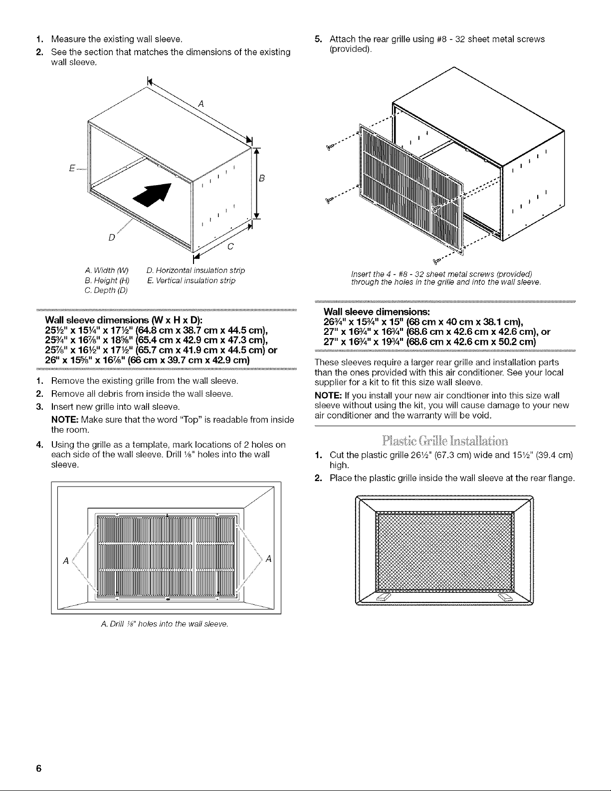
1. Measuretheexistingwallsleeve.
2. Seethesectionthatmatchesthedimensionsoftheexisting
wallsleeve.
5. Attachthereargrilleusing#8-32sheetmetalscrews
(provided).
÷.÷
÷÷
A. Width (W) D. Horizontal insulation strip
B. Height (H) E. Vertical insulation strip
C. Depth (D)
Wall sleeve dimensions ONx H x D):
25½" x 15Y4"x 17½" (64.8 cm x 38.7 cm x 44.5 cm),
25%" x 167/8'' x 18%"(65.4 cm x 42.9 cm x 47.3 cm),
257/8'' x 161/2'' x 17½" (65.7 cm x 41.9 cm x 44.5 cm) or
26" x 15%" x 16%" (66 cm x 39.7 cm x 42.9 cm)
1. Remove the existing grille from the wall sleeve.
2. Remove all debris from inside the wall sleeve.
3. Insert new grille into wall sleeve.
NOTE: Make sure that the word "Top" is readable from inside
the room.
4. Using the grille as a template, mark locations of 2 holes on
each side of the wall sleeve. Drill 1/8"holes into the wall
sleeve.
Insert the 4 - #8 - 32 sheet metal screws (provided)
through the holes in the grille and into the wall sleeve.
Wall sleeve dimensions:
26%" x 15%" x 15" (68 cm x 40 cm x 38.1 cm),
27" x 16%" x 16%" (68.6 cm x 42.6 cm x 42.6 cm), or
27" x 16%" x 19%" (68.6 cm x 42.6 cm x 50.2 cm)
These sleeves require a larger rear grille and installation parts
than the ones provided with this air conditioner. See your local
supplier for a kit to fit this size wall sleeve.
NOTE: If you install your new air condtioner into this size wall
sleeve without using the kit, you will cause damage to your new
air conditioner and the warranty will be void.
1. Cut the plastic grille 261/2'' (67.3 am) wide and 151/2'' (39.4 cm)
high.
2. Place the plastic grille inside the wall sleeve at the rear flange.
A. Drill _" holes into the wall sleeve.
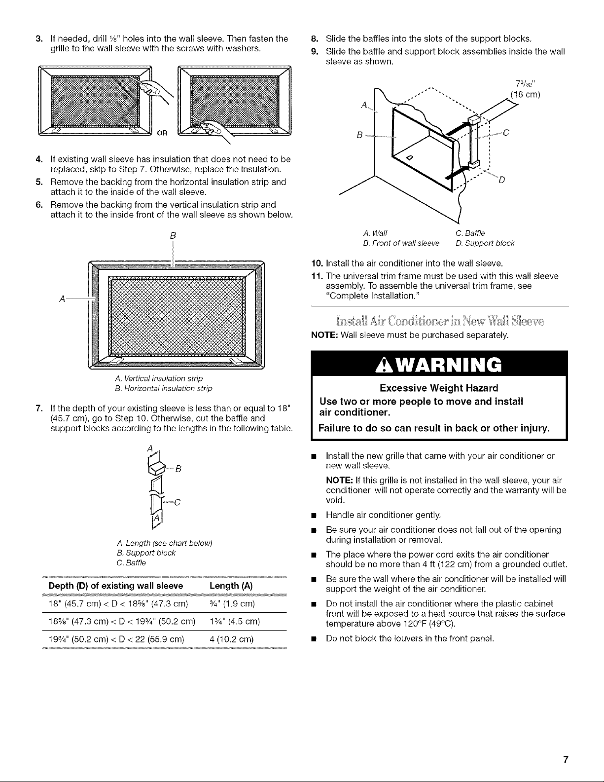
3.
If needed, drill 1/8"holes into the wall sleeve. Then fasten the
grille to the wall sleeve with the screws with washers.
8. Slide the baffles into the slots of the support blocks.
9. Slide the baffle and support block assemblies inside the wall
sleeve as shown.
73/32 ''
_(18 cm)
4. If existing wall sleeve has insulation that does not need to be
replaced, skip to Step 7. Otherwise, replace the insulation.
5. Remove the backing from the horizontal insulation strip and
attach itto the inside of the wall sleeve.
6. Remove the backing from the vertical insulation strip and
attach it to the inside front of the wall sleeve as shown below.
B
A. Vertical insulation strip
B. Horizontal insulation strip
7. If the depth of your existing sleeve is less than or equal to 18"
(45.7 cm), go to Step 10. Otherwise, cut the baffle and
support blocks according to the lengths in the following table.
.....
A. Wall
B. Front of wall sleeve
10. Install the air conditioner into the wall sleeve.
11. The universal trim frame must be used with this wall sleeve
assembly. To assemble the universal trim frame, see
"Complete Installation."
........... %
NOTE: Wall sleeve must be purchased separately.
Excessive Weight Hazard
Use two or more people to move and install
air conditioner.
Failure to do so can result in back or other injury.
C. Baffle
D. Support block
A
_'"B
A. Length (see chart below)
B. Support block
C. Baffle
Depth (D) of existing wall sleeve Length (A)
18" (45.7 cm) < D < 18%" (47.3 cm) 3/4"(1.9 cm)
18%" (47.3 cm) < D < 193/4'' (50.2 cm) 13/4'' (4.5 cm)
193/4"(50.2 cm) < D < 22 (55.9 cm) 4 (10.2 cm)
Install the new grille that came with your air conditioner or
new wall sleeve.
NOTE: If this grille is not installed in the wall sleeve, your air
conditioner will not operate correctly and the warranty will be
void.
Handle air conditioner gently.
Be sure your air conditioner does not fall out of the opening
during installation or removal.
The place where the power cord exits the air conditioner
should be no more than 4 ft (122 cm) from a grounded outlet.
Be sure the wall where the air conditioner will be installed will
support the weight of the air conditioner.
Do not install the air conditioner where the plastic cabinet
front will be exposed to a heat source that raises the surface
temperature above 120 F (49 C).
• Do not block the louvers in the front panel.
o o
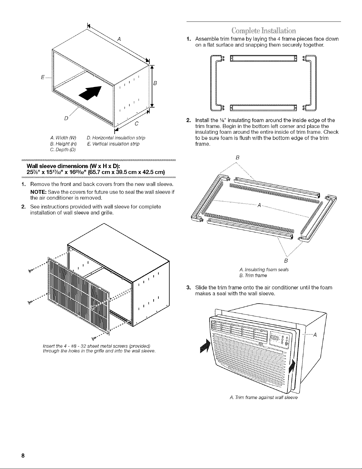
A. Width (W) D. Horizontal insulation strip
B. Height (H) E. Vertical insulation strip
C. Depth (D)
Wall sleeve dimensions (W x H x D):
25Ya" x 151%2'' x 16_/32'' (65.7 cm x 39.5 cm x 42.5 cm)
1. Remove the front and back covers from the new wall sleeve.
NOTE: Save the covers for future use to seal the wall sleeve if
the air conditioner is removed.
2. See instructions provided with wall sleeve for complete
installation of wall sleeve and grille.
Assemble trim frame by laying the 4 frame pieces face down
on a flat surface and snapping them securely together.
2.
Install the 1/8"insulating foam around the inside edge of the
trim frame. Begin in the bottom left corner and place the
insulating foam around the entire inside of trim frame. Check
to be sure foam isflush with the bottom edge of the trim
frame.
÷÷÷
_÷÷
Insert the 4 - #8 - 32 sheet metal screws (provided)
through the holes in the grille and into the wall sleeve.
\
\
Y/
B
A. Insulating foam seals
B. Trim frame
3. Slide the trim frame onto the air conditioner until the foam
makes a seal with the wall sleeve.
A. Trim frame against wall sleeve
Electrical Shock Hazard
Plug into a grounded 3 prong outlet.
Do not remove ground prong.
Do not use an adapter.
Do not use an extension cord.
Failure to follow these instructions can result in
death, fire, or eJectricaJ shock.
AIRCONDITIONERUSE
4. Plug into a grounded 3 prong outlet.
5. Press RESET on power supply cord,
Operating your air conditioner properly helps you to obtain the
best possible results,
This section explains proper air conditioner operation.
IMPORTANT:
• If you turn off the air conditioner, wait at least 3 minutes
before turning it back on. This prevents the air conditioner
from blowing a fuse or tripping a circuit breaker.
Do not try to operate your air conditioner in the cooling mode
when outside temperature is below 66°F (19°C). The inside
evaporator coil will freeze up, and the air conditioner will not
operate properly.
NOTES:
• In the event of a power failure, your air conditioner will
operate at the previous settings when the power is restored.
If the electronic control will not respond to touch pad or
remote control commands, it is necessary to unplug the unit
from the electrical outlet for 5 seconds before plugging
back in.
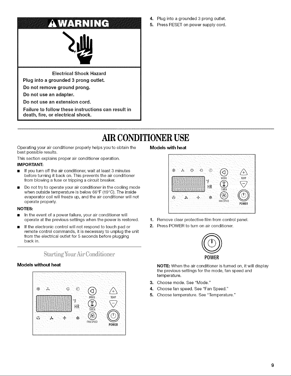
Models without heat
Models with heat
FANSPEED
1. Remove clear protective film from control panel.
2. Press POWER to turn on air conditioner.
POWER
©
POWER
NOTE: When the air conditioner is turned on, it will display
the previous settings for the mode, fan speed and
temperature.
3.
Choose mode. See "Mode."
4.
Choose fan speed. See "Fan Speed."
5.
Choose temperature. See "Temperature."
POWER
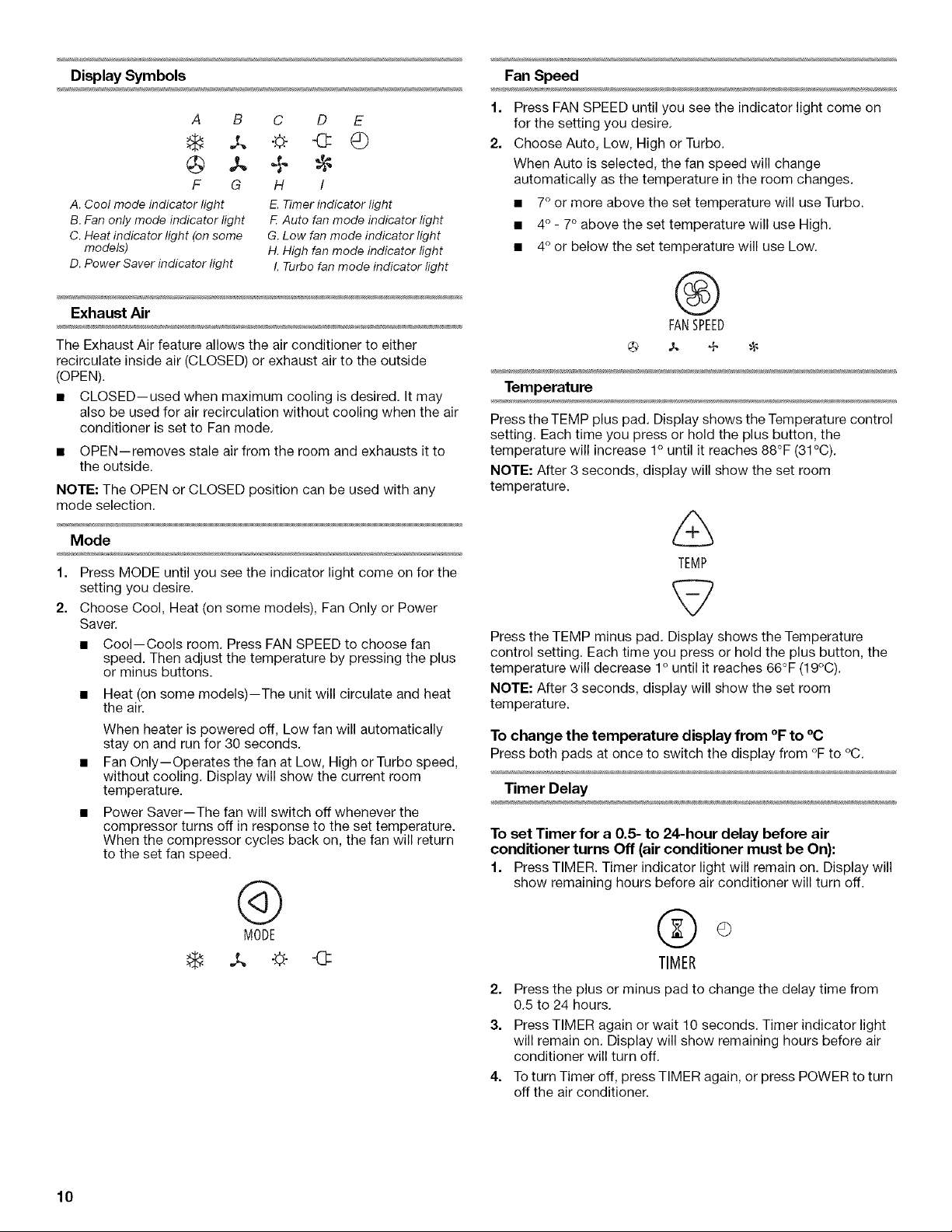
Display Symbols
Fan Speed
A B C D E
F G H /
A. Cool mode indicator light E.Timerindicator light
B.Fanonly mode indicator light F Auto fanmode indicator light
C. Heatindicator light (onsome G.Low fan mode indicator light
models) H.High fan mode indicator light
D. Power Saverindicator light I. Turbofan mode indicator light
Exhaust Air
The Exhaust Air feature allows the air conditioner to either
recirculate inside air (CLOSED) or exhaust air to the outside
(OPEN).
• CLOSED--used when maximum cooling is desired. It may
also be used for air recirculation without cooling when the air
conditioner is set to Fan mode.
• OPEN--removes stale air from the room and exhausts it to
the outside.
NOTE: The OPEN or CLOSED position can be used with any
mode selection.
Mode
1.
Press MODE until you see the indicator light come on for the
setting you desire.
2.
Choose Cool, Heat (on some models), Fan Only or Power
Saver.
• Cool--Cools room. Press FAN SPEED to choose fan
speed. Then adjust the temperature by pressing the plus
or minus buttons.
• Heat (on some models)--The unit will circulate and heat
the air.
When heater is powered off, Low fan will automatically
stay on and run for 30 seconds.
Fan Only--Operates the fan at Low, High or Turbo speed,
without cooling. Display will show the current room
temperature.
Power Saver--The fan will switch off whenever the
compressor turns off in response to the set temperature.
When the compressor cycles back on, the fan will return
to the set fan speed.
1. Press FAN SPEED until you see the indicator light come on
for the setting you desire.
2. Choose Auto, Low, High or Turbo.
When Auto is selected, the fan speed will change
automatically as the temperature in the room changes.
• 7° or more above the set temperature will use Turbo.
• 4° - 7° above the set temperature will use High.
• 4° or below the set temperature will use Low.
®
FANSPEED
,_ + "-8
Temperature
Press the TEMP plus pad. Display shows the Temperature control
setting. Each time you press or hold the plus button, the
temperature will increase 1° until it reaches 88°F (31°C).
NOTE: After 3 seconds, display will show the set room
temperature.
TEMP
Press the TEMP minus pad. Display shows the Temperature
control setting. Each time you press or hold the plus button, the
temperature will decrease 1ountil it reaches 66°F (19°C).
NOTE: After 3 seconds, display will show the set room
temperature.
To change the temperature display from °F to °C
Press both pads at once to switch the display from °F to °C.
Timer Delay
To set Timer for a 0.5- to 24-hour delay before air
conditioner turns Off (air conditioner must be On):
1. PressTIMER. Timer indicator light will remain on. Display will
show remaining hours before air conditioner will turn off.
10
@
MODE
.,t, -o:
©
TIMER
2. Press the plus or minus pad to change the delay time from
0.5 to 24 hours.
3. Press TIMER again or wait 10 seconds. Timer indicator light
will remain on. Display will show remaining hours before air
conditioner will turn off.
4. Toturn Timer off, press TIMER again, or press POWER to turn
off the air conditioner.
 Loading...