


WD 1003-RAH

USER'S GUIDE
WD 1003-RAH
WD 1003S-RAH
WD 1003-RA2
WD 1003A-RA2
Winchester
Disk Controllers
Important Information
Do not Discard
Document Scope
This document describes the hardware and software installation of the following Western
Digital controllers:
WD 1003-RAH WD 1003-RA2
WD1003S-RAH WD 1003A-RA2
Two versions of the WD1003-RA2 are available:
Feature 000 (F000). Non-translation operation only
Feature 001 (F00l). Translation operation only.
The other controllers described in this document have one standard version.
These controllers are designed for use in IBM Personal Computer ATs or other AT-c ompatible
computers with a 16-bit data bus.
The use of the term controller refers to all boards described within this document. When a
reference is made to a particular board, the appropriate WD part number is used.

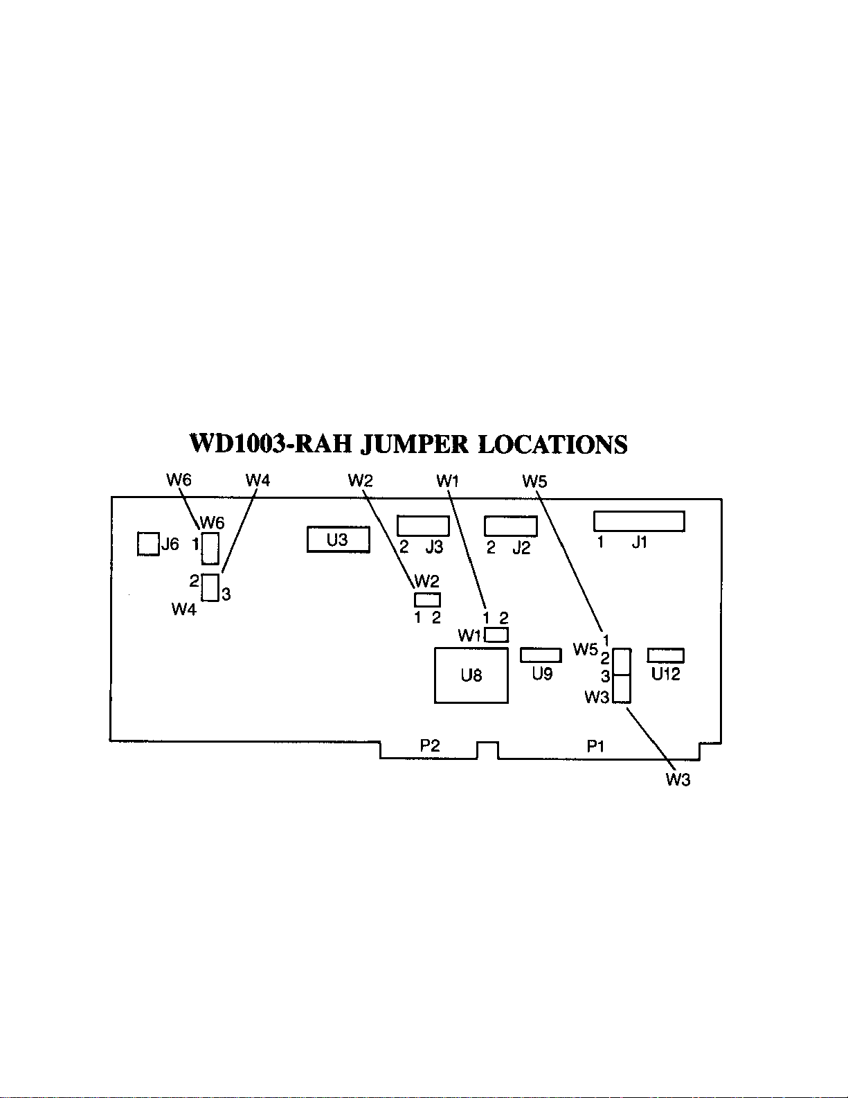
WDl003-RAH JUMPER SETTINGS
JUMPER PIN CONNECTS DESCRIPTION
W1 1-2 Standard factory setting. Status read is latched. Used for IBM
Personal Computer AT if Winchester activity LED is connected to
J6.
OPEN Status read is not latched. Activity LED turns on during drive
access. W5 must be jumpered 2 to 3. Used for Compaq hosts.
W2 OPEN Standard factory setting. Selects primary addresses, 1F0 through
1F7 and 3F0 through 3F7 hex. Do not modify the primary address
jumper unless your BIOS operating system is configured to accept
more than two hard disk drives.
1-2 Selects secondary addresses, 170 through 177 and 370 through
377 hex.
W3 OPEN
1-2
W4 2-3 Standard factory setting. No translation for drive 0.
1-2 Enables translation for drive 0. Translation is only available for
W5 2-3 Standard factory setting. WG and drive select lines only enabled
1-2 WG and drive select lines are disabled during power up reset and
W6 2-3 Standard factory setting. No translation for drive 1.
1-2 Enables translation for drive 1. Translation is only available for
This configuration used with WD11C00C-22 at board location US
or if W5 is jumpered 1 to 2. Required only on early units with
WD11C00-22 at board location U8 and W5 is jumpered 1 to 2. DO
NOT JUMPER WITH THE WDl1C00C-22 INSTALLED.
615 cylinders and four headed drives. In translation mode, the
controller translates the 26 physical sectors per track into 17
sectors. The extra sectors are "translated" into logical heads. To
use the translation mode, select through the Setup program a 615
cylinder and six head drive type. (This is drive type three for IBM
Personal Computer AT users. Not all AT-compatible systems use
the same drive tables as IBM.) This configuration must be used
when running an operating system or application program which
requires a 17 sector per track disk drive.
when drive is accessed. This configuration also provides power up
and down protection.
when + 5V power supply drops below approximately +4.1 5V.
615 cylinders and four headed drives. In translation mode, the
controller translates the 26 physical sectors per track into 17
sectors. The extra sectors are "translated" into logical heads. To
use the translation mode, select through the Setup program a 615
cylinder and six head drive type. (This is drive type three for IBM
Personal Computer AT users. Not all AT-compatible systems use
the same drive tables as IBM.) This configuration must be used
when running an operating system or application program which
requires a 17 sector per track disk drive.

Hardware Installation
This section describes installation of your hardware. If the disk drive(s) is (are) installed
internally, it is best to locate the controller in the closest available expansion slot relative to the
drive.
CAUTION
Handle the controller board by the ends of the boar d. So me of t he chips are static sensitive
and damage may occur if the board is incorrectly handled.
Furthermore, do NOT under any circumstances connect an RLL controller to an MFM
drive. Refer to “If You Have a Problem” section for further information.

WD10035-RAH JUMPER SETTINGS
JUMPER PIN CONNECTS DESCRIPTION
W1 1-2
OPEN
W2 OPEN
1-2
Standard factory setting. Status read is latched. Used for IBM Personal Computer AT
if Winchester activity LED is connected to J6.
Status read is not latched. Activity LED turns on during drive access. W5 must be
jumpered 2 to 3. Used for Compaq hosts.
Standard factory setting. Selects primary addresses, 1F0 through 1F7 and 3F0 through
3F7 hex. Do not modify the primary address jumper unless your BIOS operating
system is configured to accept more than two hard disk drives.
Selects secondary addresses, 170 through 177 and 370 through 377 hex.
W3
W4 1-2
2-3
W5 2-3
1-2
W6 1-2
2-3
W7 1-2
3-4
1-3
2-4
Applicable to the WD1003-RAH. Eliminated by design and artwork changes to the
WD1003S-RAH.
Standard factory setting. No translation for drive 0.
Enables translation for drive 0. Translation is only available for 615 cylinders and four
headed drives. In translation mode, the controller translates the 26 physical sectors per
track into 17 sectors. The extra sectors are "translated" into logical heads. To use the
translation mode, select through the Setup program a 615 cylinder and six head drive
type. (This is drive type three for IBM Personal Computer AT users. Not all ATcompatible systems use the same drive tables as IBM.) This configuration must be
used when running an operating system or application program which requires a 17
sector per track disk drive.
Standard factory setting. WG and drive select lines only enabled when drive is
accessed. This configuration also provides power up and down protection.
WG and drive select lines are disabled during power up reset and when + 5V power
supply drops below approximately +4.1 5V.
Standard factory setting. No translation for drive 1.
Enables translation for drive 1. Translation is only available for 615 cylinders and four
headed drives. In translation mode, the controller translates the 26 physical sectors per
track into 17 sectors. The extra sectors are "translated" into logical heads. To use the
translation mode, select through the Setup program a 615 cylinder and six head drive
type. (This is drive type three for IBM Personal Computer AT users. Not all ATcompatible systems use the same drive tables as IBM.) This configuration must be
used when running an operating system or application program which requires a 17
sector per track disk drive.
Standard factory setting. Controller operates with daisy-chained drive(s). Both can be
daisy-chained from J1 or drive 0 can be connected to J1 and drive 1 can be connected
to J5. For daisy-chained operation, set the drive select jumpers on the first drive for
drive 0 and on the second drive for drive 1.
Controller operates with parallel connected drives. Attach drive 1 control connector to
J1.
Attach drive 0 control connector to J5. For parallel operation, set the drive select
jumpers on both drives for drive 0.
W8 1-2
2-3
Standard factory configuration. Ties input high
Enables seek to landing zone (cylinder 663) on any seek to a cylinder greater than
615. Used only for 615 cylinder drives. This jumper also changes step rate 0 (24 µsec)
to step rate 15 (11 µsec).
.
 Loading...