


 Loading...
Ultrastar® DC HA210
(Previously known as Ultrastar 7K2)
Capacity EnterpriseHDD
HUS722T2TALA604
HUS722T1TALA604
Manual Reference echnicalT
Revision 1.1 (28 July 2016)
Revision 1.2 (01 May 2018)
One MB is equal to one million bytes, one GB is equal to one billion bytes and one TB equals 1,000GB (one trillion bytes) when referring to storage capacity. Accessible capacity will vary from the stated capacity due to formatting and partitioning of the drive, the computer’s operating system, and other factors.
The following paragraph does not apply to any jurisdiction where such provisions are inconsistent with local law: THIS PUBLICATION IS PROVIDED "AS IS" WITHOUT WARRANTY OF ANY KIND, EITHER EXPRESS OR IMPLIED, INCLUDING, BUT NOT LIMITED TO, THE IMPLIED WARRANTIES OF MERCHANTABILITY OR FITNESS FOR A PARTICULAR PURPOSE.
This publication could include technical inaccuracies or typographical errors. Changes are periodically made to the information herein; these changes will be incorporated in new editions of the publication. There may be improvements or changes in any products or programs described in this publication at any time. It is possible that this publication may contain reference to, or information about, Western Digital products (machines and programs), programming, or services that are not announced in your country. Such references or information must not be construed to mean that Western Digital Corporation intends to announce such Western Digital products, programming, or services in your country. Technical information about this product is available by contacting your local Western Digital product representative or on the Internet at: support@wdc.com.
Western Digital Corporation may have patents or pending patent applications covering subject matter in this document. The furnishing of this document does not give you any license to these patents.
© 2018 Western Digital Corporation or its affiliates.
Ultrastar, RAFF, Data Lifeguard, the Western Digital logo and Ultrastar are registered trademarks or trademarks of Western Digital Corporation or its affiliates in the U.S. and/or other countries. Other trademarks are the property of their respective owners.
References in this publication to Western Digital-branded products, programs, or services do not imply that they will be made available in all countries. Product specifications provided are sample specifications and do not constitute a warranty. Actual specifications for unique part numbers may vary. Please visit the Support section of our website, support@wdc.com, for additional information on product specifications. Pictures shown may vary from actual products.
Ultrastar® DC HA210
Technical Reference Manual

Ultrastar DC HA210
TABLE OF CONTENTS
1.0 DESCRIPTION AND FEATURES ................................................................................................................................... |
7 |
|
1.1 |
General Description ........................................................................................................ |
7 |
1.2 |
Product Features............................................................................................................. |
7 |
2.0 SPECIFICATION ................................................................................................................................................................ |
9 |
|
2.1 |
Performance Specifications ............................................................................................. |
9 |
2.2 |
CacheFlow™ ................................................................................................................. |
10 |
|
Write Cache............................................................................................................ |
10 |
2.3 |
Read Cache ............................................................................................................ |
10 |
Mechanical Specifications ............................................................................................. |
11 |
|
|
Physical Dimensions............................................................................................... |
12 |
2.4 |
Drive Mounting ...................................................................................................... |
12 |
Electrical Specifications................................................................................................. |
13 |
|
|
Mean Current Requirements and Power Dissipation................................................. |
13 |
|
Power Savings Modes ............................................................................................. |
13 |
|
Input Voltage Requirements.................................................................................... |
15 |
|
Ripple .................................................................................................................... |
15 |
2.5 |
Power Connectors and Cables ................................................................................. |
15 |
Environmental Specifications......................................................................................... |
16 |
|
|
Shock and Vibration................................................................................................ |
16 |
|
Temperature and Humidity ..................................................................................... |
17 |
|
Temperature Measurement ..................................................................................... |
17 |
|
Cooling .................................................................................................................. |
18 |
|
Atmospheric Pressure............................................................................................. |
18 |
|
Acoustics ............................................................................................................... |
18 |
2.6 |
RoHS (Restriction of HazardousSubstances) ............................................................ |
18 |
Agency Approvals......................................................................................................... |
19 |
|
2.7 |
Full Model Number Specification ................................................................................... |
19 |
3.0 PRODUCT FEATURES.................................................................................................................................................. |
20 |
|
3.1 |
SATA 6 Gb/s................................................................................................................. |
21 |
3.2 |
Time-Limited Error Recovery(TLER)............................................................................... |
21 |
3.3 |
Rotary Acceleration Feed Forward(RAFF)™ ..................................................................... |
22 |
3.4 |
Perpendicular Magnetic Recording(PMR)........................................................................ |
23 |
3.5 |
IntelliSeek..................................................................................................................... |
23 |
3.6 |
Native Command Queuing(NCQ)................................................................................... |
23 |
3.7 |
Pre-emptive Wear Leveling (PWL) ................................................................................... |
23 |
3.8 |
MicroFemto Slider......................................................................................................... |
23 |
3.9 |
S.M.A.R.T. Command Transport(SCT) ............................................................................ |
24 |
|
Write Same ............................................................................................................. |
24 |
3.10 |
Temperature Reporting........................................................................................... |
24 |
World Wide Name (WWN) ............................................................................................... |
24 |
|
3.11 |
Power Loss Data Protection ........................................................................................... |
24 |
3.12 |
Hot Plug Support .......................................................................................................... |
25 |
3.13 |
Active LED Status .......................................................................................................... |
25 |
3.14 |
Fluid Dynamic Bearings (FDB) ........................................................................................ |
25 |
3.15 |
StaggeredSpinupandActivityIndication(SATAPowerPin 11) .............................................. |
25 |
|
Staggered Spinup ................................................................................................... |
25 |
|
Activity Indication................................................................................................... |
25 |
3.16 48-bit Logical Block Addressing(LBA)............................................................................ |
26 |
|
3.17 |
Self-Monitoring, Analysis, and Reporting Technology (S.M.A.R.T.)....................................... |
26 |
3.18 |
Password Security Mode................................................................................................ |
27 |
|
Master and User Passwords..................................................................................... |
27 |
3.19 |
Security Levels........................................................................................................ |
27 |
Data Path Protection (DPP)............................................................................................. |
27 |
|
3.20 |
Manufacturing Option Block .......................................................................................... |
27 |
Hard Disk Drive Technical Reference Manual
4

Ultrastar DC HA210 |
|
|
4.0 RELIABILITY.................................................................................................................................................................... |
28 |
|
4.1 |
Reliability Considerations.............................................................................................. |
28 |
4.2 |
Error Rates.................................................................................................................... |
28 |
|
Error Rates ............................................................................................................. |
28 |
|
Environmental Interference ..................................................................................... |
29 |
4.3 |
Reliability Features Set .................................................................................................. |
30 |
|
Data Lifeguard™*.................................................................................................... |
30 |
|
Thermal Management............................................................................................. |
30 |
|
Internal Environmental ProtectionSystem ................................................................ |
30 |
|
Defect Management................................................................................................ |
30 |
|
Recoverable Errors.................................................................................................. |
30 |
|
Unrecoverable Errors .............................................................................................. |
30 |
|
Automatic Defect Retirement .................................................................................. |
31 |
|
Error Recovery Process............................................................................................ |
31 |
5.0 ATA COMMAND SET.................................................................................................................................................... |
32 |
|
5.1 |
Host Interface Commands ............................................................................................. |
32 |
|
ATA-7/ATA-8 Commands ...................................................................................... |
32 |
|
SATA Commands .................................................................................................... |
33 |
|
Obsolete Commands .............................................................................................. |
33 |
|
SCT Commands...................................................................................................... |
34 |
5.2 |
S.M.A.R.T. (B0h) ............................................................................................................ |
35 |
|
Read Attribute Values Sub-Command...................................................................... |
35 |
|
Supported Attributes .............................................................................................. |
36 |
|
Read Log Sector...................................................................................................... |
37 |
5.3 |
Identify Device (ECh) ..................................................................................................... |
38 |
5.4 |
Set Features (EFh) ......................................................................................................... |
44 |
6.0 DRIVE HANDLING AND MAINTENANCE .............................................................................................................. |
45 |
|
6.1 |
Unpacking .................................................................................................................... |
45 |
|
Handling Precautions.............................................................................................. |
45 |
|
Inspection of Shipping Container............................................................................. |
45 |
|
Removal From Shipping Container........................................................................... |
45 |
|
Removal From Static ShieldingBag .......................................................................... |
46 |
|
Moving Precautions ................................................................................................ |
46 |
6.2 |
Hard Drive Installation .................................................................................................. |
46 |
|
Backplane Usage ..................................................................................................... |
47 |
6.3 |
Maintenance................................................................................................................. |
48 |
7.0 GLOSSARY....................................................................................................................................................................... |
49 |
|
Hard Disk Drive Technical Reference Manual
5
Ultrastar DC HA210 |
|
LIST OF FIGURES |
|
Figure 1 Mounting Dimensions............................................................................................... |
11 |
Figure 2 Drive Base Casting Thermocouple Location ............................................................... |
17 |
Figure 3 Forced Airflow Direction ........................................................................................... |
18 |
Figure 4 Dual Linear Sensor Rotational Acceleration Feed Forward (RAFF)................................ |
22 |
Figure 5 Manufacturing Option Block...................................................................................... |
27 |
Figure 6 SATA Cable Connections ........................................................................................... |
46 |
Figure 7 Connector Pair Blind Mate Misalignment Allowable.................................................... |
47 |
Figure 8 Device Backplane Connection.................................................................................... |
47 |
LIST OF TABLES |
|
Table 1 Physical Specifications.................................................................................................. |
9 |
Table 2 Performance Specifications .......................................................................................... |
9 |
Table 3 Device/Head Register ................................................................................................ |
16 |
Table 4 Maximum and Reliability Operating Temperature Limits (Drive Baseplate)................... |
17 |
Table 5 Full Model Number Description .................................................................................. |
19 |
Table 6 ATA-7/ATA-8 Command Opcodes.............................................................................. |
32 |
Table 7 Optional Subcommands ............................................................................................. |
33 |
Table 8 Obsolete Command Opcodes ..................................................................................... |
33 |
Table 9 SCT Action Codes....................................................................................................... |
34 |
Table 10 Definitions for the 512 Bytes.................................................................................... |
35 |
Table 11 Supported Attributes................................................................................................ |
36 |
Table 12 Log Address Definition ............................................................................................ |
37 |
Table 13 Identify Device Command......................................................................................... |
38 |
Hard Disk Drive Technical Reference Manual
6
Ultrastar DC HA210
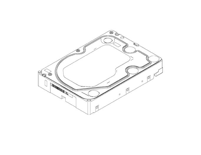
DESCRIPTION AND FEATURES
General Description
Western Digital Ultrastar Capacity Enterprise hard drives offer up to 10 TB capacities and are available with SATA interface. With the highest error tolerance and MTBF of any capacity-optimized drive, Western Digital Ultrastar delivers the durability and reliability required in tightly packed vibration prone multi-drive systems. The combination of high-capacity, peak performance and robust design make Western Digital Ultrastar drives ideal for heavy workload environments, cloud storage, RAID arrays, external storage arrays, data warehousing, and mining applications.
Product Features
Serial ATA(SATA) — Serial ATA (SATA) is the next generation bus interface for hard drives. It is designed to replace Parallel ATA, and has many advantages including increased transfer rate, improved signal integrity, enhanced data protection, and hot plug support.
Time-Limited Error Recovery (TLER) — TLER prevents hard drive error recovery fallout by limiting the time the drive spends in error recovery, providing increased performance, improved availability, and lower total cost of ownership in RAID arrays.
Rotary Acceleration Feed Forward (RAFF) — These drives employ RAFF technology to maintain hard drive performance in high vibration environments through adaptive compensation of the servo system.
Perpendicular Magnetic Recording (PMR) — With PMR technology the magnetization of each data bit is aligned vertically to the spinning disk, rather than longitudinally as has been the casein hard drive technology for decades. This enables more data on a given disk than is possible with conventional longitudinal recording, and provides a platform for future expansion of hard drive densities.
IntelliSeek™ — Key product feature that calculates optimum seek speeds to lower power consumption, noise, and vibration.
Native Command Queuing (NCQ) — Performance of a random I/O workload can beimproved through intelligent re-ordering of the I/O requests so they read/write to and from the nearest available sectors and minimize the need for additional disk revolutions or head actuator movement. This improvement can be achieved though Native Command Queing (NCQ) , which is supported by these hard drives.
Pre-emptive Wear Leveling (PWL) — This feature provides a solution for protecting the recording media against mechanical wear. In cases where the drive is so busy with incoming commands that it is forced to stay in a same cylinder position for a long time, the PWL control engine initiates forced seeks so that disk lubricant maintains an even distribution and does not become depleted. This feature ensures reliability for applications that perform a high incidence of read/write operations at the same physical location on the disk.
MicroFemto Slider — These drives incorporate the next generation of femto slider form factor in which the read/write head is mounted on the small, lightweight microfemto slider that allows the head to move more quickly from track to track on the disk.
S.M.A.R.T. Command Transport (SCT) — The SCT Command Transport feature set provides a method for a host to send commands and data to a device and for a device to send data and status to a host using log pages.
World Wide Name (WWN) — The World Wide Name (WWN) defined in ATA/ATAPI-7 is a modification of the IEEE extended unique identifier 64 bit standard (EUI-64) and is comprised of three major components: naming authority, organizationally unique identifier (OUI) and serial number.
This product’s OUI is 0014EEh.
Hard Disk Drive Technical Reference Manual
7
Ultrastar DC HA210
Reliability Features Set-Data Lifeguard™ — Representing the ongoing commitment to data protection, Data Lifeguard includes features that enhance the drive’s ability to prevent data loss. Data Lifeguard data protection utilities include thermal management, an environmental protection system, and embedded error detection and repair features that automatically detect, isolate, and repair problem areas that may develop over the extended use of the hard drive. With these enhanced data reliability features, the drive can perform more accurate monitoring, error repair, and deliver exceptional data security.
Power Loss Data Protection — Upon power loss, the drive utilizes stored spindle energy to back up the HDD cache to onboard flash. This allows deeper write queues which boosts performance, while minimizing data loss/corruption such as write splices that can occur during unexpected power losses.
Hot Plug Support — SATA supports hot plugging (also known as “hot swapping”), the ability to swap out a failed hard drive without having to power down the system or reboot. This capability contributes to both data availability and serviceability without any associated downtime, making it a critical feature for extending SATA into enterprise applications.
Active LED Status — The drive supports external LED requirements. It provides an activity LED output which is ON during command execution and OFF otherwise.
Fluid Dynamic Bearings (FDB) — Bearing design that incorporates a layer of high-viscosity lubricant instead of ball bearings in the hard drive spindle motor. As an alternative to conventional ball bearing technology, FDB designs provide increased non-operational shock resistance, speed control, and improved acoustics.
Staggered Spin-Up — Next generation SATA 6 Gb/s feature that allows the system to control whether the drive will spin up immediately or wait until the interface is fully ready.
CacheFlow™ —This unique, multi-generation caching algorithm evaluates the way data isread from and written to the drive and adapts “on-the-fly” to the optimum read and write caching methods. CacheFlow minimizes disk seek operations and overheads due to rotational latency. CacheFlow supports sequential and random write cache. With write cache and other CacheFlow features, the user can cache both read and write data. The cache can hold multiple writes and collectively write them to the hard disk.
48-bit Logical Block Addressing (LBA) — Western Digital SATA drives support both 48-bit and 28bit LBA and CHS-based addressing. LBA is included in advanced BIOS and operating system device drivers and ensures high capacity disk integration.
Power Management — The drive supports the ATA and SATA power management command set, allowing the host to reduce the power consumption of the drive by issuing a variety of power management commands.
Self-Monitoring, Analysis, and Reporting Technology (S.M.A.R.T.) — S.M.A.R.T. enables a drive’s internal status to be monitored through diagnostic commands at the host level and during offline activities. S.M.A.R.T. devices employ data analysis algorithms that are used to predict the likelihood of some near-term degradation or fault conditions. When used with a S.M.A.R.T. application, the drive can alert the host system of a negative reliability status condition. The host system can then warn the user of the impending risk of data loss and recommend an appropriate action.
ATASecurity — The drive supports the ATA Security Mode Feature set. The ATA Security Mode feature set allows the user to create a device lock password that prevents unauthorized hard disk access even if the drive is removed from the host computer. The correct password must be supplied to the hard drive in order to access user data. Both the User and Master Password features are supported, along with the High and Maximum security modes. The Master Password Revision code is also supported. This feature varies by drive configuration and may not be available on all configurations.
Data Path Protection (DPP) — A feature that prevents possible electronic failures from corrupting data on the hard drive.
Hard Disk Drive Technical Reference Manual
8
Ultrastar DC HA210
SPECIFICATION
Table 1 Physical Specifications
Physical Specifications1 |
HUS722T2TALA604 |
HUS722T1TALA604 |
Capacity |
2 TB |
1 TB |
|
|
|
Interface |
SATA 6 Gb/s |
SATA 6 Gb/s |
|
|
|
Physical Bytes Per Sector |
512 |
512 |
|
|
|
Host Bytes Per Sector |
512 |
512 |
|
|
|
User Sectors per Drive |
3,907,029,168 |
1,953,525,168 |
|
|
|
Servo Type |
Embedded |
Embedded |
|
|
|
Channel Recording Method |
LDPC–Low Density Parity Code |
|
|
|
|
1 As used for storage capacity, one megabyte (MB) = one million bytes, one gigabyte (GB) = one billion bytes, |
||
and one terabyte (TB) = one trillion bytes. Total accessible capacity varies depending on operating |
||
environment. As used for buffer or cache, one megabyte (MB) = 1,048,576 bytes. As used for transfer rate |
||
or interface, megabyte per second (MB/s) = one million bytes per second, and gigabit per second (Gb/s) = |
||
one billion bits per second. Effective maximum SATA 6 Gb/s transfer rate calculated according to the Serial |
||
ATA specification published by the SATA-IO organization as of the date of this document. Visit www.sata- |
||
io.org for details. |
|
|
|
|
|
Performance Specifications
Table 2 Performance Specifications
Average Seek (without overhead) |
7.7 ms average |
- Read |
|
- Write |
8.3 ms average |
Average Latency |
4.2 ms (nominal) |
|
|
Rotational Speed |
7200 RPM (nominal) |
|
|
Data Transfer Rate (maximum at OD) 1 |
6 Gb/s |
- Maximum burst interface transfer rate |
|
- Maximum sustained interface transfer rate |
HUS722T2TALA604: 200 MB/s |
|
HUS722T1TALA604: 184 MB/s |
Buffer Size |
128 MB |
|
|
Spindle Start Time |
15s average (FAST spinup mode) |
- From Power-on to Drive Ready 2 |
|
|
18s average (STANDARD spinup mode) |
|
|
Spindle Stop Time |
<10s average |
|
|
Load/Unload Cycles3 |
600,000 minimum |
1As used for transfer rate or interface, megabyte per second (MB/s) = one million bytes per second, and gigabit per second (Gb/s) = one billion bits per second. Effective maximum SATA 6 Gb/s transfer rate calculated according to the Serial ATAspecification published by the SATA-IO organization as of the date of this document. Visit www.sata-io.org for details.
2Defined as the time from power-on to the setting of Drive Ready and Seek Complete including calibration. Controlled unload at ambient condition.
Hard Disk Drive Technical Reference Manual
9
Ultrastar DC HA210
CacheFlow™
CacheFlow is the unique, multi-generation disk caching system. It incorporates read cache with write cache.
CacheFlow was designed to obtain maximum performance with today’s most popular operating systems and applications. CacheFlow increases performance over prior caching algorithms by increasing the number of times that requested data is in the cache. This reduces the number of host commands that require actual media access thereby improving overall drive performance.
Typical applications perform a variety of access patterns, such as random, sequential, and repetitive. CacheFlow is designed to dynamically adapt to the changes in access patterns that occur during the course of application execution.
Random mode is the default operational mode for CacheFlow. Once CacheFlow detects a sequential access pattern, it leaves random mode. CacheFlow also performs predictive read operations to increase the probability that data requested in future commands already exists in the cache.
CacheFlow partitions the buffer into multiple segments to allow for the fact that applications may access multiple non-contiguous areas on the disk. CacheFlow tracks the amount of valid data in each segment and controls the deallocation of segments to maximize drive performance.
Write Cache
CacheFlow is designed to improve both single and multi-sector write performance by reducing delays caused by seek time and rotational latency.
The write cache adaptively detects random and sequential access patterns during application execution.
If a defective sector is found during a write cache operation, that sector is automatically relocated before the write occurs.
Read Cache
CacheFlow implements a multiple segment read cache. Cache segments are assigned to read commands as they are received from the host.
Each read segment consists of pre and post read sectors in addition to the host-requested sectors. This maximizes the amount of cache data in the drive’s buffer, thereby increasing the likelihood of cache hits and improving overall performance.
Hard Disk Drive Technical Reference Manual
10

Ultrastar DC HA210
Mechanical Specifications
Figure 1 shows the mounting dimensions and locations of the screw holes for the drive.
Figure 1 Mounting Dimensions
Hard Disk Drive Technical Reference Manual
11
Ultrastar DC HA210
Physical Dimensions
|
English |
|
|
Metric |
||
|
|
|
|
|
|
|
|
Dimension |
|
Tolerance |
Dimension |
|
Tolerance |
|
|
|
|
|
|
|
Height |
1.028 inches |
|
MAX |
26.1 mm |
|
MAX |
|
|
|
|
|
|
|
Length |
5.787 inches |
|
MAX |
147.0 mm |
|
MAX |
|
|
|
|
|
|
|
Width |
4.00 inches |
|
±0.01 inch |
101.6 mm |
|
±0.25 mm |
|
|
|
|
|
|
|
Weight |
1.41 pounds |
|
±10% |
0.64 kg |
|
±10% |
|
|
|
|
|
|
|
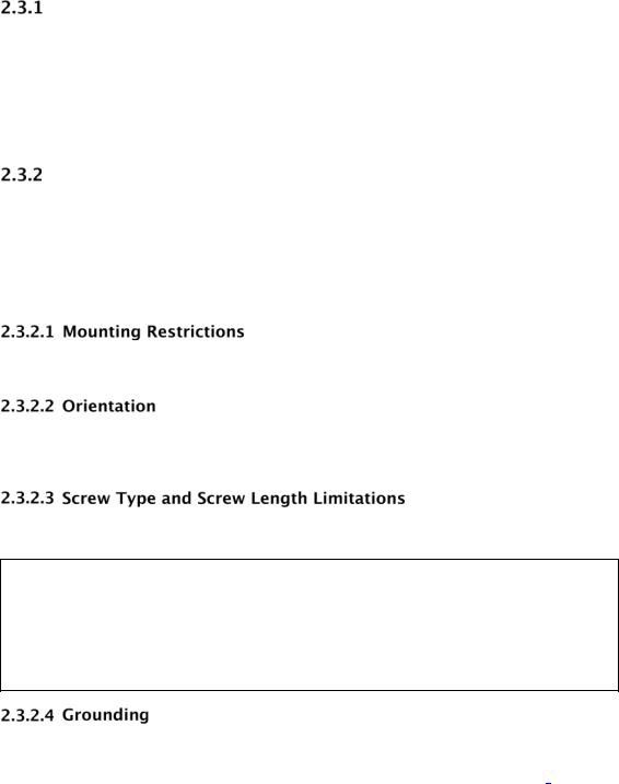
Drive Mounting
Use either the four bottom screws or at least four of the side mounting screws to rigidly support the drive and prevent vibration. Some adaptor frames may not have the mechanical design structure capable of mounting the drive to meet the specified shock and vibration requirements.
The hard drive itself does not provide electrical isolation between mounting locations and drive ground connection. If electrical isolation is required, the system designer or integrator would be responsible for providing a solution.
If your system does not support hot plugging (see “Hot Plug Support on page.25), it must be turned off and unplugged before installing your hard drive.
You can mount the hard drive in the X, Y, or Z axis, depending upon the physical design of your system. For best results, mount the drive with all four screws grounded to the chassis. If all four screws are not used, see "Grounding" on page.12.
The hard drive should be mounted to the chassis using four 6-32 screws. Recommended screw torque is 5 in-lb. Maximum screw torque is 10 in-lb.
CAUTION: Screws that are too long can damage the hard drive. Hard drive screw penetration can differ between products depending upon hard drive design. Western Ditigal’s minimum design criteria is to always meet the SFF 8301 industry standard specification. The industry standard as defined in the SFF 8301 specifies a maximum of 3 mm screw penetration, and for a minimum of 2.4 mm of thread engagement from both the screw and the hard drive.
See Figure 1 for allowable fastener penetration for this product family.
The PCBA and HDA grounds are always connected together in the drive and cannot be disconnected. The drive mounting screws, unless intentionally isolated, will provide additional ground connections between the HDA and the system chassis. If the drive isn't grounded via mounting screws as described under “Hard Drive Installation” on Page.46, there may be increased electrical emissions (EMI).
Hard Disk Drive Technical Reference Manual
12
Ultrastar DC HA210
Electrical Specifications
Mean Current Requirements and Power Dissipation
Operating Mode |
Mean Current1, 2 |
Mean Power1, 2 |
||
12 VDC |
5VDC |
|||
|
|
|||
|
|
|
|
|
Spinup Standard3 |
1710 mA (max) |
520 mA (peak) |
- |
|
|
735 mA |
295 mA |
|
|
Spinup Fast |
2385 mA (max) |
550 mA (peak) |
- |
|
|
1350 mA |
295 mA |
||
|
|
|||
Spinup Green |
1190 mA (max) |
505 mA (peak) |
- |
|
|
510 mA |
295 mA |
||
|
|
|||
Operational Peak Current |
1545 mA (peak) |
870 mA (peak) |
- |
|
|
1600 mA (max) |
860 mA (max) |
||
|
|
|||
Sequential Read |
315 mA |
720 mA |
7.4W |
|
|
|
|
|
|
Sequential Write |
315 mA |
730 mA |
7.4W |
|
|
|
|
|
|
Random Read/Write |
485 mA |
455 mA |
8.1W |
|
|
|
|
|
|
Idle |
315 mA |
430 mA |
5.9W |
|
|
|
|
|
|
1 When running at 3 Gb/s or as a single ported device, power will be lower than the value listed. 2 All peak and mean values are typical (measured at 25°C) except where specified as maximum. 3 Default spinup mode when not otherwise overridden.
Mode |
Mean Current2 |
Mean Current2 |
Mean Power2 |
|
DIPM Off |
||||
|
|
|
||
|
|
|
|
|
|
12 VDC |
5VDC |
|
|
|
|
|
|
|
Idle_A |
310 mA |
290 mA |
5.2W |
|
|
|
|
|
|
Idle_B |
295 mA |
290 mA |
5.0W |
|
|
|
|
|
|
Idle C |
110 mA |
290 mA |
2.8W |
|
|
|
|
|
|
Standby Y |
110 mA |
290 mA |
2.8W |
|
|
|
|
|
|
Standby_Z |
10 mA |
285 mA |
1.5W |
|
|
|
|
|
1When running at 3 Gb/s or as a single ported device, power will be lower than the value listed.
2All peak and mean values are typical (measured at 25°C) except where specified as maximum.
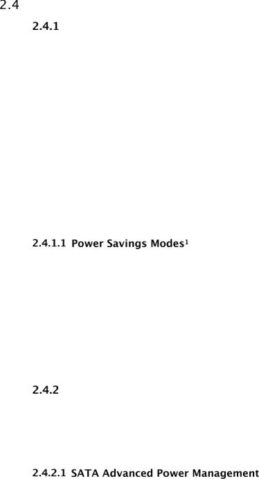
Power Savings Modes
This product is capable of supporting both legacy ATA Advanced Power Management (APM) mode and the new more extensive Extended Power Conditions (EPC) standards. Unless otherwise specified, the default disk drive is shipped with the EPC mode enabled, and the legacy APM modes can be enabled via the Set Feature command (Feature ‘4A’h, Sub Command ‘04’h). These two power savings implementations are exclusively used, and thus not simultaneously supported.
This drive supports the legacy ATA power management commands that lower the average power consumption of the hard drives. For example, to take advantage of the lower power consumption modes of the drive, an energy efficient host system could implement a power management scheme that issues a Standby Immediate command when a host resident disk inactivity timer expires. The Standby Immediate command causes the drive to spin down and enter a low-power mode. Subsequent disk access commands would cause the drive to spin up and execute the new command. To avoid excessive wear on the drive due to the starting and stopping of the HDA, set the host’s disk inactivity timer to no shorter than ten minutes.
Hard Disk Drive Technical Reference Manual
13

Ultrastar DC HA210
Western Digital drives additionally support T13 Extended Power Conditions, as stated in the ACS-2 specification. Power savings features, normally only available in notebook drives, are now included in our Enterprise products. With these features enabled, drive power can be reduced automatically via inactivity timer, or manually via Host command. In timer based mode, the drive automatically starts reducing its power based on inactivity of commands from the Host. With progression into the idle states, the drive saves more and more power, but consequently takes longer to recover and respond to Host media commands.
A summary of the new low power modes and what the drive does in each mode is shown below:
Idle_A
Heads Floating Over Disk <10 ms recovery
Idle_B
Heads Parked <650 ms recovery
Idle_C
Heads Parked, Reduced RPM
3-15 sec recovery (see the Power Conditions Log for the drives actual recovery time) Idle_c recovery current limited to the maximum user mode power.
Standby_Y
Heads Parked, Reduced RPM
3-15 sec recovery (see the Power Conditions Log for the drives actual recovery time) Standby_y recovery can use full spin up power.
Standby_Z
Traditional standby Drive not spinning
Recovery is similar to a typical TTR (Time To Ready) for the HDD
Western Digital has added the Power Condition Log, which defines the support, enable bits, and timers for all power conditions. The power management timers start running after all Host commanded drive activity is complete, and will run during drive background operations, but do not take effect until those background operations are completed. The timer expiration min/max values are visible to the Host/ Initiator, but are rounded silently by the drive to its internal min/max values. The timer enable and timer values can be marked independently as changeable. Please note that some Host Operating Systems may be unable to take advantage of the inactivity timers, as they constantly access the Drive with writes to update a time stamp. In these situations it is advisable to extend the Idle_B timer value beyond the time interval of the writes, or to disable the timer entirely. Please see your Western Digital representative for help with questions about these features.
Hard Disk Drive Technical Reference Manual
14
Ultrastar DC HA210
Input Voltage Requirements
The input voltage requirements are +5.0V ± 5% and +12.0V ± 10%.
Ripple
|
+ 12 VDC |
+ 5 VDC |
|
|
|
Maximum Frequency |
200 mV (double amplitude) 0-30 MHz |
100 mV (double amplitude) 0-30 MHz |
|
|
|
Power Connectors and Cables
Serial ATA Connectors
For information on SATA data connectors, including the pin definitions of the SATA connectors and the corresponding signal names and signal functions, refer to the latest SATA specification available for download at www.serialata.org.
Cabling Requirements for Serial ATA
The SATA cable consists of four conductors in two differential pairs. The cable may also include drain wires to be terminated to the ground pins in the SATA cable receptacle connectors. See the SATA specification for cable specifications. The cable's maximum length is one meter.
Hard Disk Drive Technical Reference Manual
15

Ultrastar DC HA210
Environmental Specifications
Shock and Vibration
Table 3 Device/Head Register
Shock
Operating |
30G, 2 ms read/write) |
|
|
|
|
|
|
|
||
|
65G, 2 ms (read) |
|
|
|
|
|
|
|
|
|
Non-operating (2 ms) |
300G |
|
|
|
|
|
|
|
|
|
Note: Half-sine wave, measured without shock isolation and without non-recoverable errors. |
|
|
||||||||
|
|
|
|
|
|
|
|
|
|
|
Rotational Shock Non-Operating |
|
|
|
|
|
|
|
|
||
|
|
|
|
|
|
|
|
|
|
|
Amplitude |
20K rad/sec2 |
|
|
|
|
|
|
|
|
|
Duration |
2 ms |
|
|
|
|
|
|
|
|
|
|
|
|
|
|
|
|
|
|
|
|
Vibration |
|
|
|
|
|
|
|
|
|
|
|
|
|
|
|
|
|
|
|
|
|
Operating |
Swept Sine: 20-300 Hz, 0.75G (0 to peak) |
|
|
|
|
|
||||
|
Sweep Rate: 0.5 octave/minute minimum |
|
|
|
|
|
||||
|
Random: 0.004 g2 /Hz (10-300 Hz) |
|
|
|
|
|
||||
Non-operating |
Swept Sine: 20-500 Hz, 4.0G (0 to peak) |
|
|
|
|
|
||||
|
Sweep Rate: 0.5 octave/minute minimum |
|
|
|
|
|
||||
|
Random: 0.05 g2 /Hz (10-300 Hz) |
|
|
|
|
|
||||
Rotational Vibration |
|
|
|
|
|
|
|
|
|
|
|
|
|
|
|
|
|
|
|||
12.5 rad/sec2 based on the following PSD profile maintaining <20% performance degradation: |
|
|||||||||
|
Frequency (Hz) |
|
20 |
200 |
|
300 |
900 |
|
1400 |
2000 |
|
|
|
|
|
|
|
|
|
|
|
|
(Rad/sec2)2/Hz |
|
0.035 |
0.035 |
|
0.2 |
0.2 |
|
0.002 |
0.002 |
Operating Vibration
Drives are tested by applying a random excitation in each linear axis, one axis at a time. The drive incurs no physical damage and no hard errors while subjected to continuous vibration not exceeding the level listed in Table 3 Operating performance may degrade during periods of exposure to continuous vibration.
NonOperating Vibration
Note: This specification applies to handling and transportation of unmounted drives.
Drives are tested by applying a random excitation in each linear axis, one axis at a time. The drive incurs no physical damage when subjected to continuous vibration not exceeding the level listed in Table 3.
Packaged Shock and Vibration
The shipping packaging is designed to meet the National/International Safe Transit Association (N/ ISTA) standards for packaged products. The drive incurs no physical damage when subjected to the N/ ISTA standards.
Hard Disk Drive Technical Reference Manual
16
Loading...