


Place this chapter in the OVEN section of the equipment manual.
WELLS BLOOMFIELD, LLC |
903 |
10 Sunnen Drive P.O.Box 430195 St. Louis, MO 63143 USA telephone: 314-781-2777
fax: 314-781-2714 www.wellsbloomfield.com
M4200 Convection Oven
OWNERS MANUAL
VENTED CONVECTION OVEN
MODEL
M4200-3S
M4200-3SEU
Includes
Installation
Use & Care
Programming
Exploded View
Parts List
Wiring Diagram
This instruction is for the exclusive use of licensees and employees of McDonalds Systems, Inc.
IMPORTANT: DO NOT DISCARD THIS MANUAL
This manual is considered to be part of the appliance and is to be given to the OWNER or MANAGER of the restaurant, or to the person responsible for TRAINING OPERATORS of this appliance. Additional manuals are available from your WELLS DEALER.
THIS MANUAL MUST BE READ AND UNDERSTOOD BY ALL PERSONS USING OR INSTALLING THIS APPLIANCE. Contact your WELLS DEALER if you have any questions concerning installation, operation or maintenance of this equipment.
PRINTED IN UNITED STATES OF AMERICA
p/n 2M-307323 Rev. F |
M903 090923 |

INTRODUCTION
IMPORTANT: Use only factory authorized service parts.
For factory authorized service, or to order factory authorized replacement parts, contact your Wells authorized service agency, or call:
Wells Bloomfield, LLC
10 Sunnen Dr., P.O.Box 430129
St. Louis MO 63143 USA
Service Dept.
phone: (314) 781-2777 fax: (314) 781-2714
Thank You for purchasing this Wells Bloomfield appliance.
Proper installation, professional operation and consistent maintenance of this appliance will ensure that it gives you the very best performance and a long, economical service life.
This manual contains the information needed to properly install this appliance, and to use and care for the appliance in a manner that will ensure its optimum performance.
M4200/M4200EU Manual Owners 307323-2M M903
xi

M903 2M-307323 Owners Manual M4200/M4200EU
TABLE OF CONTENTS
|
AGENCY LISTING INFORMATION |
1 |
||
|
WARRANTY |
2 |
||
GENERAL |
PRECAUTIONS & GENERAL INFORMATION |
3 |
||
|
SPECIFICATIONS |
4 |
||
|
INSTALLATION |
5 |
||
|
FEATURES & OPERATING CONTROLS |
|
||
|
OVEN FEATURES |
8 |
||
|
SMART CONTROLLER |
10 |
||
OPERATION |
OPERATION |
12 |
||
|
QUICK-GLANCE OPERATING GUIDE |
|||
|
DAILY SET-UP |
13 |
||
|
COOK CYCLE OPERATION |
14 |
||
|
PROGRAMMING |
|
||
|
|
IMPORTANT: |
|
|
|
Programming to be performed by Qualified Personnel ONLY! |
|||
|
ENTER PROGRAMMING MODE |
15 |
||
PROGRAMMING |
CHANGE PROGRAMMED SETTINGS |
16 |
||
ENABLING SCRATCH BISCUIT BUTTON (#6) |
18 |
|||
|
||||
|
INSTRUCTIONS TO CHANGE COOKIE SETTINGS |
19 |
||
|
INSTALL OPERATING SYSTEMS SOFTWARE |
20 |
||
|
TRANSFER MENUS FROM CARD TO OVEN |
21 |
||
|
TRANSFER MENUS FROM OVEN TO CARD |
21 |
||
|
DEFAULT SETTINGS |
22 |
||
MAINTENANCE |
CLEANING INSTRUCTIONS |
23 |
||
TROUBLESHOOTING SUGGESTIONS |
25 |
|||
|
||||
|
PREVENTATIVE MAINTENANCE |
26 |
||
|
TEMPERATURE CALIBRATION |
27 |
||
|
HINGE ADJUSTMENT |
|
||
SERVICE |
EXPLODED VIEW and PARTS LIST |
28 |
||
|
||||
|
WIRING DIAGRAM M4200-3S 208V |
32 |
||
|
|
M4200-3S 240V |
33 |
|
|
|
M4200-3SEU |
34 |
|
|
PARTS & SERVICE |
37 |
||
|
CUSTOMER SERVICE DATA FORM |
37 |
||
|
|
AGENCY LISTING INFORMATION |
||
This appliance conforms to NSF Standard 4 for sanitation only if |
STD 4 |
|||
installed in accordance with the supplied Installation Instructions and |
||||
maintained according to the instructions in this manual. |
|
|||
M4200-3S (domestic) ovens are |
and |
listed under UL File |
E6070 |
|
E6070 for 208V and 240V. |
|
|
|
|
M4200-3SEU (European) ovens comply with |
standards |
E6070 |
||
|
||||
for 380-415V 3NAC
1

LIMITED WARRANTY STATEMENT
The following equipment manufactured by WELLS BLOOMFIELD, LLC for sale to McDonald's, Inc. is warranted against defects in materials and workmanship for a period of two years from the date of installation (as indicated by the installation punch-tag on the equipment), and is for the benefit of the original purchaser:
a.M4200-3 Convection Oven (208V and 240V models
only)
b.1016BVM Coffee Brewer
All other equipment manufactured by WELLS BLOOMFIELD, LLC for sale to McDonald's, Inc. is warranted against defects in materials and workmanship for a period of one year from the date of installation (as indicated by the installation punch-tag on the equipment), and is for the benefit of the original purchaser:
THE FOREGOING OBLIGATION IS EXPRESSLY GIVEN IN LIEU OF ANY OTHER WARRANTIES, EXPRESSED OR IMPLIED, INCLUDING ANY IMPLIED WARRANTY OF
MERCHANTABILITY OR FITNESS FOR A PARTICULAR PURPOSE, WHICH ARE HEREBY EXCLUDED.
WELLS BLOOMFIELD, LLC SHALL NOT BE LIABLE FOR INDIRECT, INCIDENTAL OR CONSEQUENTIAL DAMAGES OR LOSSES FROM ANY CAUSE WHATSOEVER.
This warranty is void if it is determined that upon inspection by an Authorized Service Agency that the equipment has
been modified, misused, misapplied, improperly installed, or damaged in transit or by fire, flood or act of God.
It also does not apply if the serial nameplate has been removed or unauthorized service personnel perform service. The prices charged by Bloomfield Industries for its products are based upon the limitations in this warranty. Seller’s obligation under this warranty is limited to the repair of defects without charge by a Wells Bloomfield Authorized Service Agency or one of its sub-agencies. This service will be provided on customer’s premises for non-portable models. Portable models (a device with a cord and plug) must be taken or shipped to the closest Authorized Service Agency, transportation charges prepaid, for services.
In addition to restrictions contained in this warranty, specific limitations are shown below (Additional Warranty Exclusions). Bloomfield Industries Authorized Service Agencies are located in principal cities.
This warranty is valid in the United States and void elsewhere. Please consult your classified telephone directory or your food service equipment dealer; or, for information and other details concerning warranty, write to:
Wells Bloomfield, LLC
10 Sunnen Dr., P.O.Box 430129 St. Louis MO 63143 USA phone (314) 781-2777 or fax (314) 781-2714
for information and other details concerning warranty.
SERVICE POLICY AND PROCEDURE GUIDE and ADDITIONAL WARRANTY EXCLUSIONS
1.Resetting of safety thermostats, circuit breakers, over load protectors, and/or fuse replacements are not covered by this warranty unless warranted conditions are the cause.
2.All problems due to operation at voltages or phase other than specified on equipment nameplates are not covered by this warranty.
Conversion to correct voltage and/or phase must be the customer’s responsibility.
3.All problems due to electrical connections not made in accordance with electrical code requirements and wiring diagrams supplied with the equipment are not covered by this warranty.
4.Replacement of items subject to normal wear, to include such items as knobs, light bulbs; and, normal maintenance functions including adjustments of thermostats, adjustment of micro switches and replacement of fuses and indicating lights are not covered by warranty.
5.Damage to electrical cords and/or plug due to exposure to excessive heat are not covered by this warranty.
6.Full use, care, and maintenance instructions supplied with each machine. Noted maintenance and preventative maintenance items, such as servicing and
cleaning schedules, are customer responsibility. Those miscellaneous adjustments noted are customer responsibility. Proper attention to preventative maintenance and scheduled maintenance procedures will prolong the life of the appliance.
7.Travel mileage is limited to sixty (60) miles from an Authorized Service Agency or one of its sub-service agencies.
8.All labor shall be performed during regular working hours. Overtime premium will be charged to the buyer.
9.All genuine Wells replacement parts are warranted for ninety (90) days from date of purchase on nonwarranty equipment. This parts warranty is limited only to replacement of the defective part(s). Any use of non-genuine Wells parts completely voids any warranty.
10.Installation, labor, and job check-outs are not considered warranty and are thus not covered by this warranty.
11.Charges incurred by delays, waiting time or operating restrictions that hinder the service technician’s ability to perform service are not covered by warranty. This includes institutional and correctional facilities.
SHIPPING DAMAGE CLAIM PROCEDURE
NOTE: For your protection, please note that equipment in this shipment was carefully inspected and packaged by skilled personnel before leaving the factory. Upon acceptance of this shipment, the transportation company assumes full responsibility for its safe delivery.
IF SHIPMENT ARRIVES DAMAGED:
1.VISIBLE LOSS OR DAMAGE: Be certain that any visible loss or damage is noted on the freight bill or express receipt, and that the note of loss or damage is signed by the delivery person.
2.FILE CLAIM FOR DAMAGE IMMEDIATELY:
Regardless of the extent of the damage.
3.CONCEALED LOSS OR DAMAGE: if damage is unnoticed until the merchandise is unpacked, notify the transportation company or carrier immediately, and file “CONCEALED DAMAGE” claim with them. This should be done within fifteen (15) days from the date the delivery was made to you. Be sure to retain the container for inspection.
Wells Bloomfield cannot assume liability for damage or loss incurred in transit. We will, however, at your request, supply you with the necessary documents to support your claim.
M4200/M4200EU Manual Owners 307323-2M M903
2
M903 2M-307323 Owners Manual M4200/M4200EU
PRECAUTIONS AND GENERAL INFORMATION
This appliance is intended for use in commercial establishments only.
This appliance is intended to prepare food for human consumption. No other use is recommended or authorized by the manufacturer or its agents.
Operators of this appliance must be familiar with the appliance use, limitations and associated restrictions. Operating instructions must be read and understood by all persons using or installing this appliance.
Cleanliness of this appliance is essential to good sanitation. Read and follow all included cleaning instructions and schedules to ensure the safety of the food product.
Disconnect this appliance from electrical power before performing any maintenance or servicing.
DO NOT submerge this appliance in water. This appliance is not jet stream approved. Do not direct water jet or steam jet at this appliance, or at any control panel or wiring. Do not splash or pour water on, in or over any controls, control panel or wiring. Do not wash floor around this appliance with water or steam jet.
Exposed surfaces of this appliance can be hot to the touch and may cause burns.
Do not operate this appliance if the control panel is damaged. Do not operate this appliance if the keypad section of the control panel is torn or broken. Call your Authorized Wells Service Agent for service.
The technical content of this manual, including any wiring diagrams, schematics, parts breakdown illustrations and/or adjustment procedures, is intended for use by qualified technical personnel.
Any procedure which requires the use of tools must be performed by a qualified technician.
This manual is considered to be a permanent part of the appliance. This manual and all supplied instructions, diagrams, schematics, parts breakdown illustrations, notices and labels must remain with the appliance if it is sold or moved to another location.
This appliance is made in the USA. Unless otherwise noted, this appliance has American sizes on all hardware.
 WARNING:
SHOCK HAZARD
All servicing requiring access to non-insulated electrical components must be performed by a factory authorized technician.
DO NOT open any access panel which requires the use of tools. Failure to follow this warning can result in severe electrical shock.
 CAUTION:
RISK OF
DAMAGE
DO NOT connect or energize this appliance until all installation instructions are read and followed. Damage to the appliance will result if these instructions are not followed.
CAUTION:
HOT SURFACE
Exposed surfaces can be hot to the touch and may cause burns.
3

SPECIFICATIONS
DIMENSIONS |
APPLIANCE |
OVEN CAVITY |
|
Wide |
30-1/8” (765mm) |
14-3/8” (365mm) |
|
Deep |
25-1/4” (641mm) oven only |
21” (533mm) |
|
|
27-7/8” (682mm) incl. handle |
|
|
High |
25-1/8” (638mm) oven only |
20” (508mm) |
|
|
34” (863mm) incl. prep-top\ |
|
|
|
and casters |
|
|
Door Swing |
20" (508mm )radius |
|
|
ELECTRICAL |
|
|
|
M4200-3S |
208 VAC 3ø 60Hz 8750 kW total |
21 Amps per leg |
|
M4200-3S |
240 VAC 3ø 60Hz 8750 kW total |
21 Amps per leg |
|
M4200-3SEU |
380-415V 3NAC 5-/60Hz |
L1 |
11.7 Amps |
|
8750 kW total |
L2 |
11.7 Amps |
|
|
L3 |
11.7 Amps |
|
|
N |
1.0 Amps |
Note: Shipped from the factory 3 phase with pin-and-sleeve electrical plug.
Unit is NOT approved for conversion to single phase.
M4200/M4200EU Manual Owners 307323-2M M903
4

M903 2M-307323 Owners Manual M4200/M4200EU
UNPACKING & INSPECTION
Carefully remove the appliance from the carton. Remove all protective plastic film, packing materials and accessories from the Appliance before connecting electrical power or otherwise performing any installation procedure.
Carefully read all instructions in this manual and the Installation Instruction Sheet packed with the appliance before starting any installation.
Read and understand all labels and diagrams attached to the appliance.
Carefully account for all components and accessories before discarding packing materials. Store all accessories in a convenient place for later use.
COMPONENTS
3 ea. OVEN RACKS
2 ea. RACK SUPPORTS
1 ea. FAN BAFFLE ACCESSORIES
1 ea. LITERATURE PACKAGE
OPTIONAL ACCESSORIES
22882 Stacking and Venting Kit
505504 Venting Duct Assembly Kit (single oven)
SERVICE TECHNICIAN INSTALLATION NOTES
1.Installation and start up should be performed by an authorized installation company. Installer must record installation particulars on the CUSTOMER SERVICE DATA form on page 33 of this manual.
2.Verify that this equipment installation is in compliance with the specifications listed in this manual and with local code requirements.
INSTALLATION
NOTE: DO NOT discard the carton or other packing materials until you have inspected the appliance for hidden damage and tested it for proper operation.
Refer to SHIPPING DAMAGE CLAIM PROCEDURE on the inside front cover of this manual.
 WARNING:
 RISK OF INJURY
Installation procedures must be performed by a qualified technician with full knowledge of all applicable electrical and plumbing codes. Failure can result in personal injury and property damage.
IMPORTANT:
It is the RESPONSIBILITY OF THE INSTALLER to check with the AUTHORITY HAVING JURISDICTION, in order to verify compliance with local codes and ordinances for THIS SPECIFIC EQUIPMENT INSTALLATION.
5
INSTALLATION (continued)
|
|
|
WARNING: |
|
|
|
SHOCK HAZARD |
|
|
|
All servicing requiring |
access |
|
to non-insulated elec- |
|
trical |
components must be |
||
performed by a factory authorized technician.
DO NOT open any access panel which requires the use of tools. Failure to follow this warning can result in severe electrical shock.
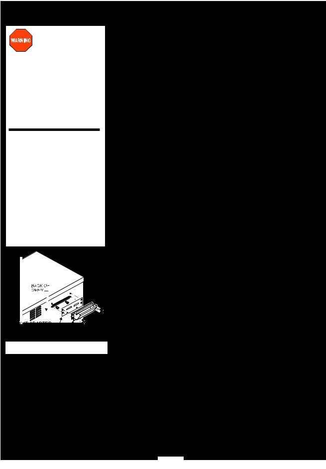
NOTE: Oven is shipped with biscuit baking adapter plate attached to rear panel.
If oven is used exclusively for bread products (bread, pies, etc.), DO NOT remove adapter.
If oven is used for proteins, install optional external vent kit #505504. Protein requires additional venting to decrease
release of cooking vapors when opening the door.
Vent Duct Installation
EQUIPMENT SET-UP
1.IF CONVECTION OVEN IS TO BE USED FOR PROTEINS, INSTALL EXTERNAL DUCT
a.Remove two screws at each end of adapter plate on back of oven.
b.Loosen two screws at bottom of adapter plate. Remove adapter plate.
c.Slide bottom flange of vent duct over the two loosened screws. D. Install four and tighten screws at ends of vent duct, then
tighten bottom screws.
2.CURB or COUNTER MOUNTING
a.Setup the appliance only on a firm, level, non-combustible surface. Verify local codes for requirements. Concrete, tile, terrazzo or metal surfaces are recommended. Metal over combustible material may not meet code for non-combustible surfaces.
b.Appliance is approved for installation with zero clearance at bottom.
c.Recommend at least 3” clearance on sides and back to allow adequate air flow.
3.INSTALLING OPTIONAL CASTERS (NOTE: casters are not provided and must be purchased separately: kits 21372 & 21373.)
a.Install casters, one on each corner of the appliance, in the holes provided. Locking casters must be installed on the FRONT of the appliance.
b.Set up the appliance only on a firm, level, non-combustible surface. Verify local codes for requirements. Concrete, tile, terrazzo or metal surfaces are recommended. Metal over combustible material may not meet code for non-combustible surfaces.
c.LEVELING: Verify that the appliance sits firmly on all four casters when in its normal operational position. With a spirit level, check that the appliance is level front-to-back and side-to-side.
4.INSTALLING OPTIONAL LEGS (NOTE: Legs are not provided
and must be purchased separately: (kit 22226.)
a.Install adjustable legs, one on each corner of the appliance, in he holes provided.
b.Set up the appliance only on a firm, level, non-combustible surface. Verify local codes for requirements. Concrete, tile, terrazzo or metal surfaces are recommended. Metal over combustible material may not meet code for non-combustible surfaces.
c.LEVELING: Verify that the appliance sits firmly ON ALL FOUR LEGS. With a spirit level, check that the appliance is level front-to-back and side-to-side.
5.OTHER OPTIONAL KITS
a.Kit 21445 Prep Top allows the top of the M4200 to be used as an NSF 4-compliant work surface.
b.Kit 21342 Oven Stacking Kit allows M4200 units to be stacked 2-high. The kit provides extended ducting for the vent system.
c.Kit 505504 - Convert to protein oven.
M4200/M4200EU Manual Owners 307323-2M M903
6
M903 2M-307323 Owners Manual M4200/M4200EU
INSTALLATION (continued)
DANGER: SHOCK HAZARD
ELECTRICAL CONNECTIONS MUST BE MADE BY A
LICENSED ELECTRICIAN Electrical shock will cause death or serious injury.
Refer to the nameplate on the front of the appliance.
•Verify the ELECTRICAL SERVICE POWER.
•Voltage and phase must match the nameplate specifications, and electrical service amps must meet or exceed the specifications listed on page 1.
IMPORTANT:
The appliance is shipped from the factory wired for 3-phase (3ø) electrical service. This appliance is not approved for 1ø operation. Conversion of this appliance to single-phase operation will void the warranty.
M4200-3S (domestic) field wiring must be no less than 10 AWG 4 conductor solid copper wire, rated for at least 90ºC.
NOTE: Wire gauge, insulation type and temperature rating , as well as type, size and construction of conduit, must meet or exceed applicable specifications of local codes and of the National Electrical Code.
This appliance is equipped with a Hubbell™ L430P9 plug, which must be plugged into a matching Hubbell™ L430R9 receptacle. The ground lug of the receptacle must be connected to a suitable building ground.
M4200-3SEU (European) field wiring must have a minimum cross-sectional area of 1.5mm2.
IMPORTANT: An approved all pole power disconnect switch,
With at least 3 mm contact gap, must be supplied and installed in the
!fixed wiring in an accessible location (close proximity to the appliance) by a licensed electrician.
NOTE: Strain relief supplied loose is for metal conduit connection. For flexible power cords an approved strain relief fitting must be supplied by others.
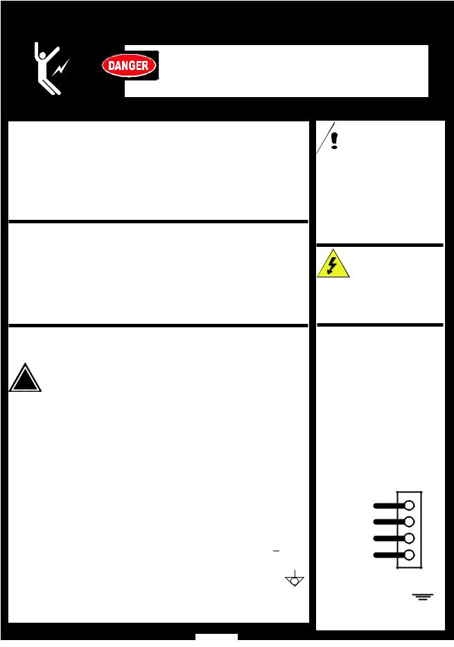
EU INSTALLATION INSTRUCTIONS:
1.Using a screwdriver, remove terminal access panel located behind front door marked: NOTICE - REMOVE THIS PANEL FOR TERMINAL BLOCK
2.Knock out the appropriate hole plug located on enclosure panel and connect conduit strain relief.
3.Thread supply leads through strain relief
•Connect supply power lines to terminals marked: L1, L2, L3
•Connect the neutral line terminal marked: N
•Connect green-with-yellow-stripe lead to ground lug marked 
4.Secure all connections and reinstall terminal access cover.
5.“Equal Potential” grounding screw is located at rear of frame, marked Remove screw and secure an appropriate grounding wire with terminal.
 CAUTION:
RISK OF
DAMAGE
DO NOT connect or energize this appliance until all installation instructions are read and followed. Damage to the appliance will result if these instructions are not followed.
CAUTION:
SHOCK HAZARD
The ground lug of this appliance must be connected to a suitable building ground.
IMPORTANT:
Contact a licensed electrician to install and connect electrical power to the appliance.
IMPORTANT:
Damage due to being connected to the wrong voltage or phase is NOT covered by warranty.
IMPORTANT PROGRAMMING NOTE:
This oven is pre-programmed from the factory and normally does not require programming adjustments.
EU Connections
SUPPLY LINE 3 |
L3 |
SUPPLY LINE 2 |
L2 |
SUPPLY LINE 1 |
L1 |
NEUTRAL |
N |
GROUND 

7

FEATURES & OPERATING CONTROLS
M4200 CONVECTION OVEN FEATURES
M4200/M4200EU Manual Owners 307323-2M M903
8
M903 2M-307323 Owners Manual M4200/M4200EU
FEATURES & OPERATING CONTROLS (continued)
ITEM
A.OPTIONAL PREP TOP
B.OVEN TOP
C.OVEN DOOR
D1. DOOR HANDLE
D2. DOOR STRIKER & LATCH E. ACCESS PANEL
F1. COOLING FAN INLET
F2. COOLING LOUVERS
G.POWER CORD
(not provided on EU models)
H.CORD HANGER
I.EXTERNAL CAVITY VENT
J.OPTIONAL FRONT CASTERS
K.OPTIONAL REAR CASTERS
L.POWER FUSES
M.DATA PLATE
N.POWER PLUG
(not provided on EU models)
P.CARD READER
Q.MENU CARD
R.ON/OFF SWITCH
S.SMART CONTROLLER
T.BEEPER
U.RACK SUPPORTS
V.PRODUCT RACK
W.HEATING ELEMENTS
X.FAN
Y.FAN BAFFLE
DESCRIPTION FUNCTION
Allows top of oven to be used as a work surface
Covers and protects top insulation
Covers and provides access to oven cavity
Safe hand hold to open or close oven.
Striker and doormounted latch hold oven door closed
Covers and provides access to fan motor and electric connections and controls
Provides air circulation for cooling. DO NOT spray or pour water into cooling fan inlet or louvers
Supplies power from receptacle to oven
Provides storage for cord when moving oven
Cooking fumes are vented here
Allow oven to be easily moved; locking to stabilize oven when in position
Allow oven to be easily moved.
Protect electrical circuits from overload
Provides manufacturer, model and serial number information. Also, provides electrical specifications and requirements
Plugs into power receptacle
Reads menu card
Contains default information; used to reprogram smart controller with default settings in the event of program errors
Energizes appliance
Controls cooking times and temperatures; selectable pre-programmed settings.
DO NOT spray or pour water into controller
Audible indicator for alarms, end-of-cycle, etc.
Hold cooking racks
Holds product to be cooked
Provide cooking heat when energized
Circulates heated air during cooking
Covers fan, also provides mounting for right rack support
9

FEATURES & OPERATING CONTROLS (continued)
SMART CONTROLLER
M4200/M4200EU Manual Owners 307323-2M M903
10
 Loading...