

Welch Allyn CP300 Service Handbook
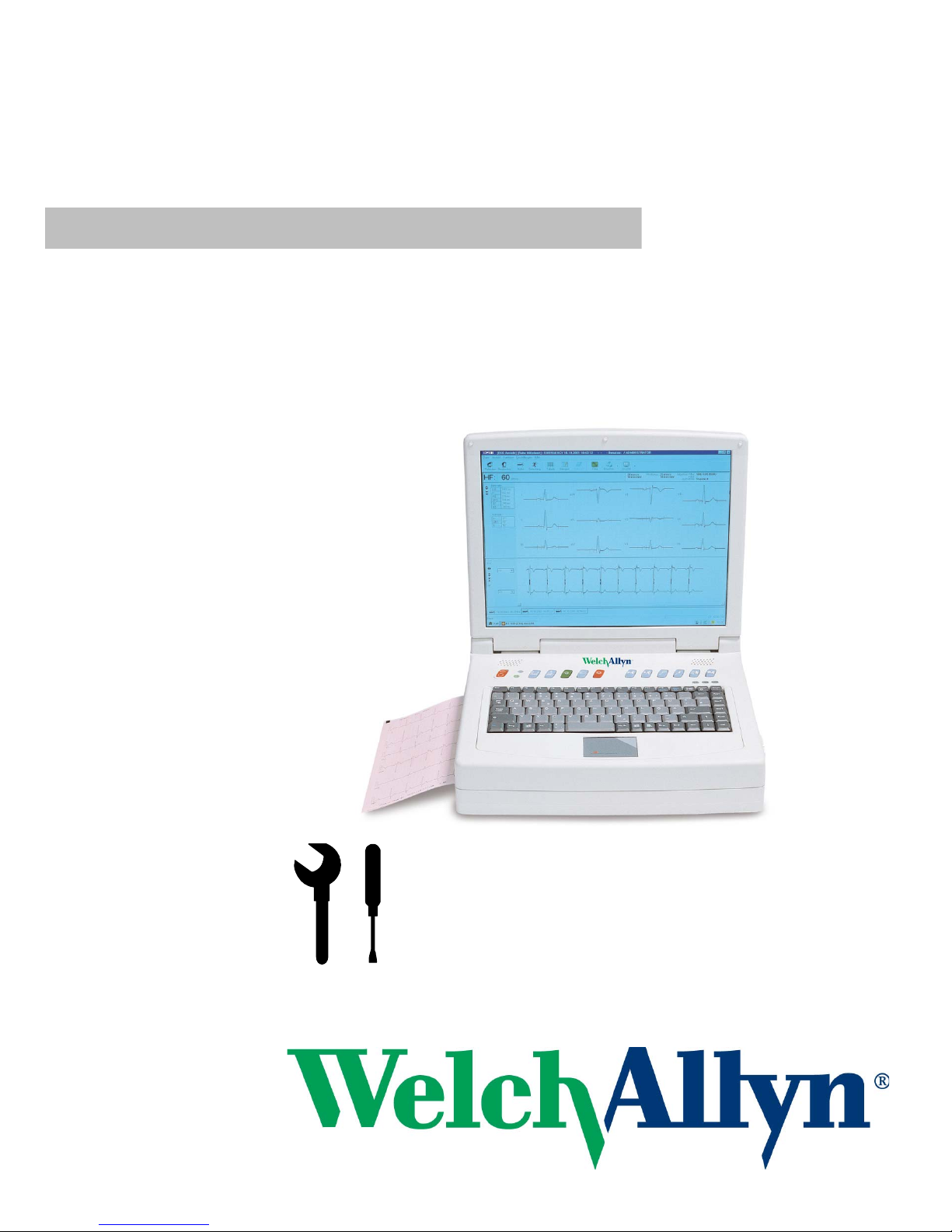
CP300
Service handbook
Art. no.: 714095 rev.: b 2.540052
12 Channel ECG Recorder

Distributed by
Welch Allyn
4341 State Street Road, PO Box 220
Skaneateles Falls, NY 13153-0220
www.welchallyn.com
Produced by
SCHILLER AG
Altgasse 68
CH-6341 Baar, Switzerland
Sales and Service information:
For information about any Welch Allyn product, please call Welch Allyn Technical Support:
USA 1 800 535 6663
+ 1 315 685 4560
Australia + 61 29 638 3000
Canada 1 800 561 8797
China + 86 216 327 9631
European Call Center + 353 46 906 7790
France + 331 6009 3366
Germany + 49 747 792 7186
Japan + 81 33 219 0071
Latin America + 1 305 669 9003
Netherlands + 31 15 750 5000
Singapore + 65 6419 8100
South Africa + 27 11 777 7555
United Kingdom + 44 207 365 6780
Sweden + 46 85 853 6551
Welch Allyn LTD.
Navan Business Park
Dublin Road
Navan, County Meath, Republic of Ireland
Tel.: 353-46-90-67700
Fax: 353-46-90-67755
Article No: 714095 rev.: b
SAG 2.540052
Issue date: 26.01.10

Page 3
Service handbook CP300
Art. no.: 714095 rev.: b
Contents
1 Safety Notes ..............................................7
1.1 Responsibility of the User .................................................. 7
1.2 Intended Use......................................................................... 7
1.3 Organizational Measures..................................................... 7
1.4 Safety-conscious Operation................................................ 8
1.5 Safety Facilities ................. ... ... ... ... .... ................................... 8
1.6 Operation with other Devices.............................................. 8
1.7 Safety Symbols and Pictograms................................... ... ... 9
1.7.1 Symbols Used in this Document........... .................................... ... ...... 9
1.7.2 Symbols Used on the Device........................................................... 10
1.8 Terms of warranty .............................................................. 10
2 Introduction ............................................11
2.1 Standard Features.............................................................. 11
2.2 Options................................................................................ 11
2.3 Main Components of the CP300........................................ 12
2.4 Operating Philosophy ........................................................ 12
2.5 Default Login Codes........................................................... 13
2.6 Keypad................................................................................. 14
2.7 External Connections......................................................... 15
2.7.1 Back Panel ....................................................................................... 15
2.7.2 Side Panel........................................................................................ 16
2.8 The Display ......................................................................... 17
3 Function Keys .........................................18
3.1 Function Key Table ............................................................ 18
4 Operation ................................................19
4.1 Start-up and Initial Preparation......................................... 19
4.1.1 Location............................................................................................ 19
4.1.2 Connection of External Cable Assemblies and Ancillary Equipment 19
4.1.3 Potential equalization....................................................................... 19
4.1.4 Switching ON and OFF.................................................................... 20
4.1.5 Power Supply and Backup Battery Operation.................................. 20
4.1.6 Isolating the Mains Supply............................................................... 20
4.1.7 System and ECG Settings ........................................................... ... . 20
4.2 Glide Point Controller Operation ...................................... 21
4.2.1 Connecting a Mouse or Trackball Device ........................................ 21
4.3 Changing the Printing Paper ............................................ 22
5 Physical and Functional Overview .......23
5.1 Physical Overview............................................. ... ... ... .... ... . 23
5.2 Functional Overview .......................................................... 23

Page 4
Service handbook CP300
Art. no.: 714095 rev.: b
6 Functional Checks .................................26
6.1 Service interval................................................................... 26
6.2 General Unit Integrity Check ............................................. 27
6.2.1 Procedure......................................................................................... 27
6.2.2 Continuous Printout (Internal thermal printer only).......................... 28
6.3 Functional Checks and Tests............................................ 29
6.3.1 External Sight Control...................................................................... 29
6.3.2 Mains and Battery Indicators (LED) test .......................................... 30
6.3.3 Battery Capacity Check.................................................................... 30
6.3.4 Keyboard Test............................................... ... ................................ 30
6.3.5 LCD Screen Test.............................................................................. 31
6.3.6 Printer Checks...................... ... .................................... ... .................. 32
6.3.7 ECG Amplifier and Patient Cable Test (Electrode/ Lead Resistance) 33
6.3.8 ECG Printout Reference.................................................................. 34
6.4 I / O Port Checks................................................................. 37
6.4.1 Equipment Required ........................................................................ 37
6.4.2 Checking the RS-232 ports.............................................................. 38
6.5 Safety tests ................. ... .... ... ... ... ........................................ 39
6.5.1 Maximum Values Safety Test.......................................................... 39
7 Software, Firmware and Test Screen ...40
7.1 Unit Settings ......... ... ... ... .... ... ... ... ... ..................................... 41
7.1.1 Importing / Exporting / Reset to Default........................................... 41
7.2 Updating Firmware............................................................. 42
7.3 Updating the Software ..................... ... ... ... .... ... ... ... ... .... ... . 42
7.4 Updating the Unit Options................................................. 43
7.5 Tests Screen ......... ... ... ... .... ... ... ... ... .... ... ... ... .... ... ... ... ... .... ... . 44
8 Replacing Major Components ...............45
8.1 Safety Notes............................. ... ... .... ... ... ... .... ... ... ... ... .... ... . 45
8.2 Overview.............................................................................. 45
8.3 Opening the Unit................................................................. 46
8.4 Main Board MK 17-1 & PC1-1 Board................................. 47
8.5 ECG Board MK 16-2........................................................ ... . 48
8.6 Thermal Printer........................................ ... .... ... ... ... ... .... ... . 48
8.6.1 Removing......................................................................................... 48
8.6.2 Replacing......................................................................................... 48
8.7 Battery ................................................................................. 48
8.8 Reassembling the Unit....................................................... 49
8.8.1 Internal Sight Control ....................................................................... 49
8.8.2 Functional Test................................................................................. 49
9 Unit Settings ...........................................50
9.1 Settings at Administrator login level................................ 50
9.1.1 System............................................................................................. 50
9.1.2 Login/Startup, Users, Institutes, Departments ................................. 54
9.1.3 ECG................................................................................................. 55
9.2 Settings at Physician/Administrator level........................ 56
9.2.1 General Filter................................................................................... 56
9.2.2 QRS /Trigger / DC Input / DC Output............................................... 57

Page 5
Service handbook CP300
Art. no.: 714095 rev.: b
9.2.3 Function Freeze............................................................................... 58
9.2.4 Show Start Recording Dialogue....................................................... 58
9.2.5 ECG Settings Filter and Lead Order................................................ 59
9.2.6 ECG Settings Printer and Printout settings...................................... 60
9.2.7 Exercise ECG Settings..................................................................... 61
9.2.8 View................................................................................................. 62
9.2.9 Defining a Protocol................................................ ... ... ..................... 63
10 Maintenance ............................................65
10.1 Cleaning .............................................................................. 65
10.1.1 Cleaning the Casing......................................................................... 65
10.1.2 Cleaning the Patient Cable .............................................................. 65
10.1.3 Cleaning the Thermal Print Head..................................................... 65
10.2 Trouble Shooting............................... ... ... ... .... ... ... ... ... .... ... . 66
10.2.1 Trouble Shooting Table.................................................................... 66
10.3 Master Reset ...................... ... ... ... ... .... ... ... ... .... ... ... ... ... .... ... . 67
10.4 Changing the Mains Fuse .................................................. 68
10.4.1 Fuse Types ...................................................................................... 68
10.4.2 Changing a Fuse.............................................................................. 68
11 Technical Data ........................................69
11.1 System................................................................................. 69
11.2 ECG...................................................................................... 70
11.3 Safety Standards ................................................................ 71
11.4 EMC Information................................................................. 72
11.4.1 Electromagnetic Emissions - Table 201 ........................................... 72
11.4.2 Immunity - Table 202 ...................................................................... 72
11.4.3 Emissions Equipment and Systems - Table 204.............................. 73
11.4.4 Recommended Separation Distances - Table 206 .......................... 74
12 Construction Drawings .......................... 75
12.1 Upper Assembly ................................................................. 75
12.2 LCD Assembly .................................................................... 76
12.3 Lower Casing ...................................................................... 77
12.4 Interconnections................................................................. 78
12.5 Isolation Diagram ....................... ... .... ... ... ... .... ... ................. 79
12.6 EMC Concept ..................................................................... 80
13 Checklist .................................................81
13.1 CP300 checklist table......................................................... 81

Page 6
Service handbook CP300
Art. no.: 714095 rev.: b
Page 7
Art. no.: 714095 rev.: b
Safety Notes 1
Service handbook CP300 Responsibility of the User 1.1
1 Safety Notes
This Service Handbook is for qualified service personnel only, trained by Welch Allyn.
Refer to the operating instruction manual 714250 for operation the device.
1.1 Responsibility of the User
1.2 Intended Use
1.3 Organizational Measures
Specify the competencies of the personnel for operation and repair.
Ensure that service personnel have read and understood these service
instructions. In particular this section “safety notes" must be read and
understood.
Have damaged or missing components replaced immediately.
The service personnel is responsible for compliance with all applicable accident
prevention regulations and safety regulations.
The CP300 is a 12-channel, ECG device used for the recording, analysis and
evaluation of ECG Recordings. Recordings made with the CP300 can be used as
a diagnostic aid for heart function and heart conditions. The CP300 is designed
for indoor use and can be used for all patients of both sexes, all races, and all
ages.
Only operate the device in accordance with the specified technical data.
Do not use or repair this unit in areas where the re is any d anger of explo sion o r
in the presence of flammable gases such as anaesthetic agents.
Before servicing the unit, ensure that an introduction regarding the unit functions
and the safety precautions has been provided by Welch Allyn
Keep these service instructions in an accessible place for reference when
required. Make sure that they are always complete and legible.
Observe the operating instructions and service instructions.
These service instructions do not override any statutory or local regulations, or
procedures for the prevention of accidents and environmental protection.
1 Safety Notes
1.4 Safety-conscious Operation
Page 8
Art. no.: 714095 rev.: b
1.4 Safety-conscious Operation
1.5 Safety Facilities
1.6 Operation with other Devices
Do not place any liquids on the unit. If liquid shoul d be spilled over the device,
immediately disconnect the device from the mains and wipe it. The device must
be serviced before reusing.
Danger of electric shock! Do not open the device without disconnecting the
device from the mains.
Before cleaning and to isolate the mains power supply, sw itch the unit off and
disconnect it from the mains by removing the plug.
Do not use high temperature sterilizatio n processes
(such as autoclaving). Do not use E-beam or gamma radiation sterilization.
Do not use solvent or abrasive cleaners on either the unit or cable assemblies.
Do not, under any circumstances, immerse the unit or cable assemblies in liquid.
Operating the device without the correctly rated fuse, or with defective cables,
constitutes a danger to life. Therefore:
– Do not operate the unit if the earth connection is suspect or if the mains lead is
damaged or suspected of being damaged.
– Damaged cable connections and connectors must be replaced immediately.
– The electrical safety devices, such as fuses, must not be altered.
– Ruptured fuses must only be replaced with the same type and rating as the
original.
Use only accessories and other parts recommended or supplied by Welch Allyn.
Use of other than recommended or supplied parts may result in injury, inaccurate
information and/or damage to the unit.
Ancillary equipment connected to the analogue and/o r d igital interfaces must b e
certified according to the respective IEC standards (e.g. IEC/EN 60950 for data
processing equipment and IEC/EN 60601-1 for medical equipment). Furthermore
all configurations shall comply with the valid version of the system standard IEC/
EN 60601-1-1. Everybody who connects additional equipment to the signal input
part or signal output part configures a medical system, and is therefore
responsible that the system complies with the requirements of the valid version
of the system standard IEC/EN 60601-1-1. If in doubt, consult the technical
service department or your local representative.
– EC/EN 60601-1-1 states that the patient must remain at least 5 feet clear of the
unit. If this is not possible, a safety isolating transformer must be installed.
Page 9
Art. no.: 714095 rev.: b
Safety Notes 1
Service handbook CP300 Safety Symbols and Pictograms 1.7
1.7 Safety Symbols and Pictograms
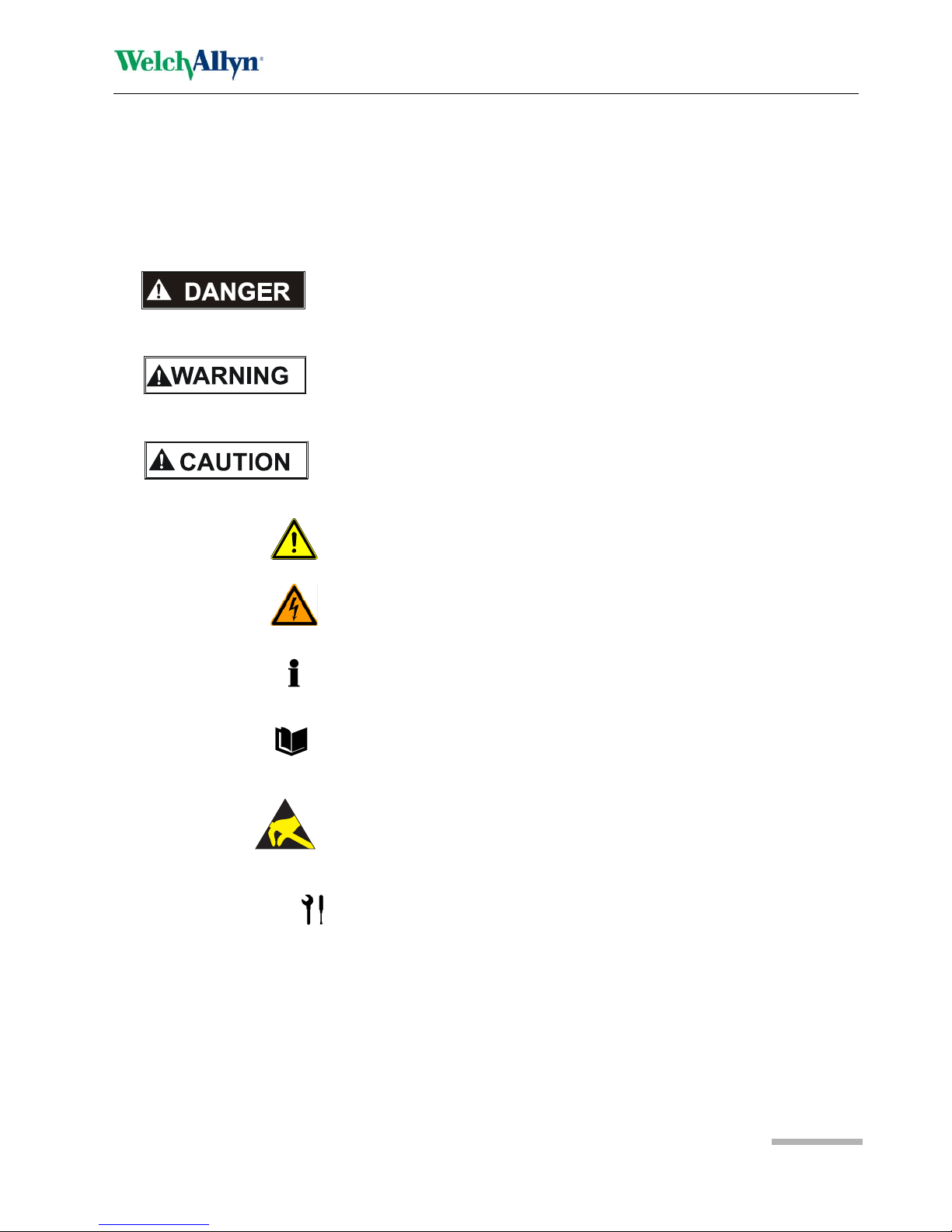
1.7.1 Symbols Used in this Document
The safety level is classified according ANSI Z535.4. The fol lowing overview shows
the used safety symbols and pictograms used in this manual.
For a direct danger which could lead to severe personal injury or to death.
For a possibly dangerous situation, which could lead to heavy bodily injury or to death.
For a possibly dangerous situation which could lead to personal injury. This symbol is
also used to indicate possible damage to property.
For general safety notes as listed in this chapter.
Used for electrical dangers, warnings and other notes in regarding operation w ith
electricity.
Note For possibly dangerous situations, which could lead to damages to property or
system failure. Important or helpful user information
Reference to other guidelines
Observe precautions for handling electrostatic sensitive devices
Tools required for a procedure.

1 Safety Notes
1.8 Terms of warranty
Page 10
Art. no.: 714095 rev.: b
1.7.2 Symbols Used on the Device
1.8 Terms of warranty
The Welch Allyn CP300 is warranted against defects in material and manufacture for
the duration of one year (as from date of purchase). Excluded from this guarantee is
damage caused by an accident or as a result of improper handling. The warranty
entitles free replacement of the defective part. Any liability for subsequent damage is
excluded. The warranty is void if unauthorized or unqualified persons attempt to make
repairs.
In case of a defect, send the apparatus to your dealer or directly to the manufacturer.
The manufacturer can only be held responsible for the safety, reliability, and
performance of the apparatus if:
• assembly operations, extensions, readjustments, modifications, or repairs are
carried out by persons authorized by him, and
• the Welch Allyn CP300 and approved attached equipment is used in accordance
with the manufacturers instructions.
Potential equalization
CF symbol. This unit is classified safe for internal and external use. However, It is only
defibrillation protected when used with the original patient cable!
Inappropriate disposal can lead to environmental pollution.
Units/components and accessories no longer required can be returned to Welch Allyn
for disposal. Alternatively, the unit should be disposed o f in a municipally approved
recycling center.
Notified body of the CE certification (TÜV P.S.)
Attention: Consult accompanying documents.

Page 11
Art. no.: 714095 rev.: b
Introduction 2
Service handbook CP300 Standard Features 2.1
2Introduction
The Welch Allyn CP300 is a diagnostic workstation designed to record, display,
archive, present, and analyse ECG recordings and other measurements. 12-lead
resting ECG recordings give measurements, interpretation, average cycles and
rhythm sections as standard. Exercise testing includes predefined stress protocols
and dedicated keys for treadmill control. All leads and measurements can be printed
in the format most convenient to the physician and print formats can be predefined.
2.1 Standard Features
• Simple one key operation with dedicated function keys and icons
• Glide point controller for menu and function selection
• Resting ECG with measurements and average cycles
• Storage facilities for ECGs
• Interfaces for control of digital ergometers / treadmills
• Automatic and real-time manual ECG recording
• Integrated quality thermal printer
2.2 Options
• ECG interpretation
• Exercise ECG with analysis program with ST measurement, average co mplexes
and trends
• External Printer
• External pointing control device (e.g. mouse, trackball)
• Externa
l keyboard
• SEMA-200 database
2 Introduction
2.3 Main Components of the CP300
Page 12
Art. no.: 714095 rev.: b
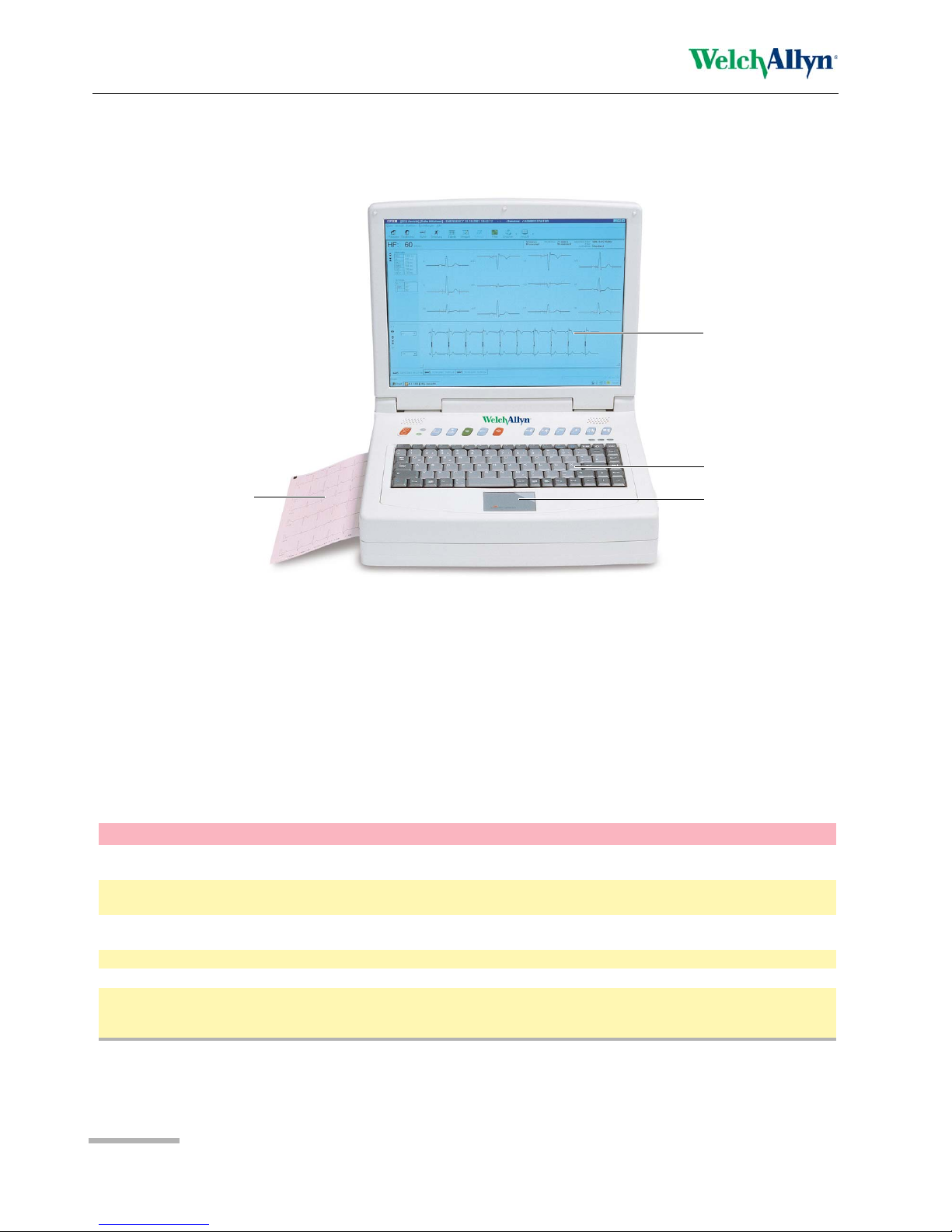
2.3 Main Components of the CP300
2.4 Operating Philosophy
The operating philosophy of the CP300 is that users are allocated user rig hts which
allow access to specific functions. Several user levels are available. It is the system
administrator / Manufacturers technician who defines the users
and allocates the user
level.
The levels are as follows:
LCD Monitor
Glide point controller
Integrated thermal
printer and paper
tray
Keyboard
Level User Rights
Emergency This only allows the user to carry out and view an emergency ECG. Any user can
carry out an emergency ECG without login.
Medical technician Recording (resting and exercise ECGs), patient data entry and patient data edi ting.
Viewing of all recordings.
Physician As above plus validation of all recordings in a defined department. Access to all user
settings.
Supervising Physician As above plus validation of all recordings in any department.
Administrator As above without validation. Access to all system settings and defining new users.
Manufacturers Technician Access to all system settings and defining new users. The manufacturers technician
cannot make a recording (except emergency), and has no access to patient data or
patient recordings.

Page 13
Art. no.: 714095 rev.: b
Introduction 2
Service handbook CP300 Default Login Codes 2.5
2.5 Default Login Codes
There are default login codes for Manufacturers technician and Administrator
login levels. Only Manufacturers technician login level has access to unit firmware
update, software option update and other menu options. The default logins are as
follows:
Manufacturers technician User Name: sysop
Password: pt160
Administrator User Name: admin
Password: serial number of the unit
The serial number of the unit is printed on a label attached to the bottom of the unit.
Use the last 3 digits of the number ignoring any preceding `0`s. In the example given,
`163` is number that must be entered.
Menu options and function icons are only displayed on the screen when u ser rights
allow. This User Guide makes no distinction for the settings available. If a menu item
or function described in this book is not available, check your user level displ ayed at
the top of the screen.
Users are defined in the settings menu > Login/startup, Users, Departments.....
(see page 50).

2 Introduction
2.6 Keypad
Page 14
Art. no.: 714095 rev.: b
2.6 Keypad
(1) Alpha-numeric keyboard. The keys F1 to F10 have varying functions depending
on use (see page 18).
(2) Glide point controller (see page 21)
(3) On/off key
(4) Power Source Indicators - mains (upper indicator) and battery (lower indica-
tor). The mains indicator shows that mains is connected: the battery lamp
indicates that the unit is running on battery power (mains power disconnected
during use - limited screen display and printout possibilities).
(5) Paper tray open close key for paper replacement.
(6) Easy print (and Emergency) Key - obtain a printout in no rmal use and an
(emergency) printout at any time in the event of mains power failure, or screen
failure.
(7) Auto Key - start an ECG recording (resting) in auto mode.
(8) Manual key - continuous printout of ECG.
(9) Stop key - stop printout, run paper to start position.
Dedicated Exercise Keys
Keys 10 to 15 are keys dedicated to exercise testing.
(10) Start test
(11) Interrupt test (and stop treadmill)
(12) Hold Stage
(13) Next Stage
(14) Recovery Stage
(15) Stop Test
3456789
10 11 12 13 14
1
2
15
The keyboard can be slightly
different depending of what
version was delivered.
Part. nr. 4.150076 = WA PN 714279
Part. No:4.150231
Page 15
Art. no.: 714095 rev.: b
Introduction 2
Service handbook CP300 External Connections 2.7
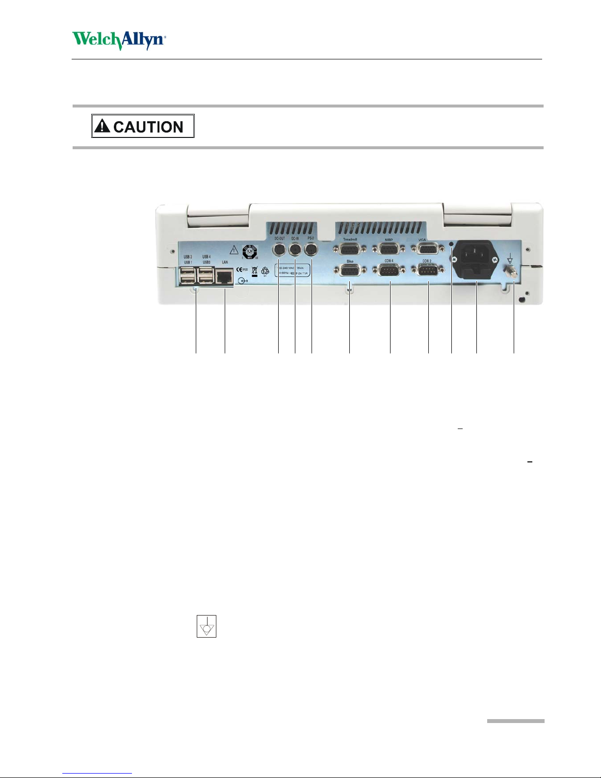
2.7 External Connections
2.7.1 Back Panel
(1) Four USB connectors (Universal Serial Bus (version 1.1 protocol)). The USB
connectors are used for connection of USB devices e.g. mouse, printer, bar-
code reader, wireless LAN etc.
(2) LAN - Network connector (RJ45).
(3) DC out connector for the output of dc signals (range +10 V) to, for example,
another ECG device or monitor. Also used for the trigger output for the BP-200
BP unit.
(4) DC In connector for the input of dc (ECG) signals from another unit (range +
2.5
V).
(5) PS-2 connector for the connection of an external pointing device (e.g. mou s e,
trackball), or external keyboard. Use the Welch Allyn Y-cable, for connection of
an external keyboard.
– When an external point and control device (e.g. mouse) is connected, the glide
point controller is disabled. Similarly, when an external keyboard is conne cted,
the CP300 keyboard is disabled.
(6) Bike connection (EXT 1, RS-232) : Treadmill (EXT 2, RS-232)
(7) NIBP connection (EXT 3 , RS-232) COM 4 - not connected.
(8) COM 2 (RS-232) - Connection of a spiro sensor: VGA - monitor connector for
VGA standard monitors.
(9) Master (Hardware) Reset.
(10) Mains connector.
(11) Potential equalizati on stud. The potential equalization stud is used to equalize
the ground potential of the unit to that of any nearby mains powered equipment.
Use the hospital or building common ground for all mains powered units.
All externally connected hardware must be approved by Welch Allyn. Connection
of any hardware not approved by Welch Allyn is at the owner‘s risk. The un it
guarantee may also be invalid.
1 2 3 6 10 1145 7
8
9

2 Introduction
2.7 External Connections
Page 16
Art. no.: 714095 rev.: b
2.7.2 Side Panel
The connection for the ECG patient cable is situated on the right hand si de panel of
the unit.
• The patient cable and connector is CF rated, that is fully floating and isolated,
defibrillation protected, suitable for intra-cardiac application.
• The unit is only CF rated and defibrillation protected if used with the original patient
cable.
©
Page 17
Art. no.: 714095 rev.: b
Introduction 2
Service handbook CP300 The Display 2.8
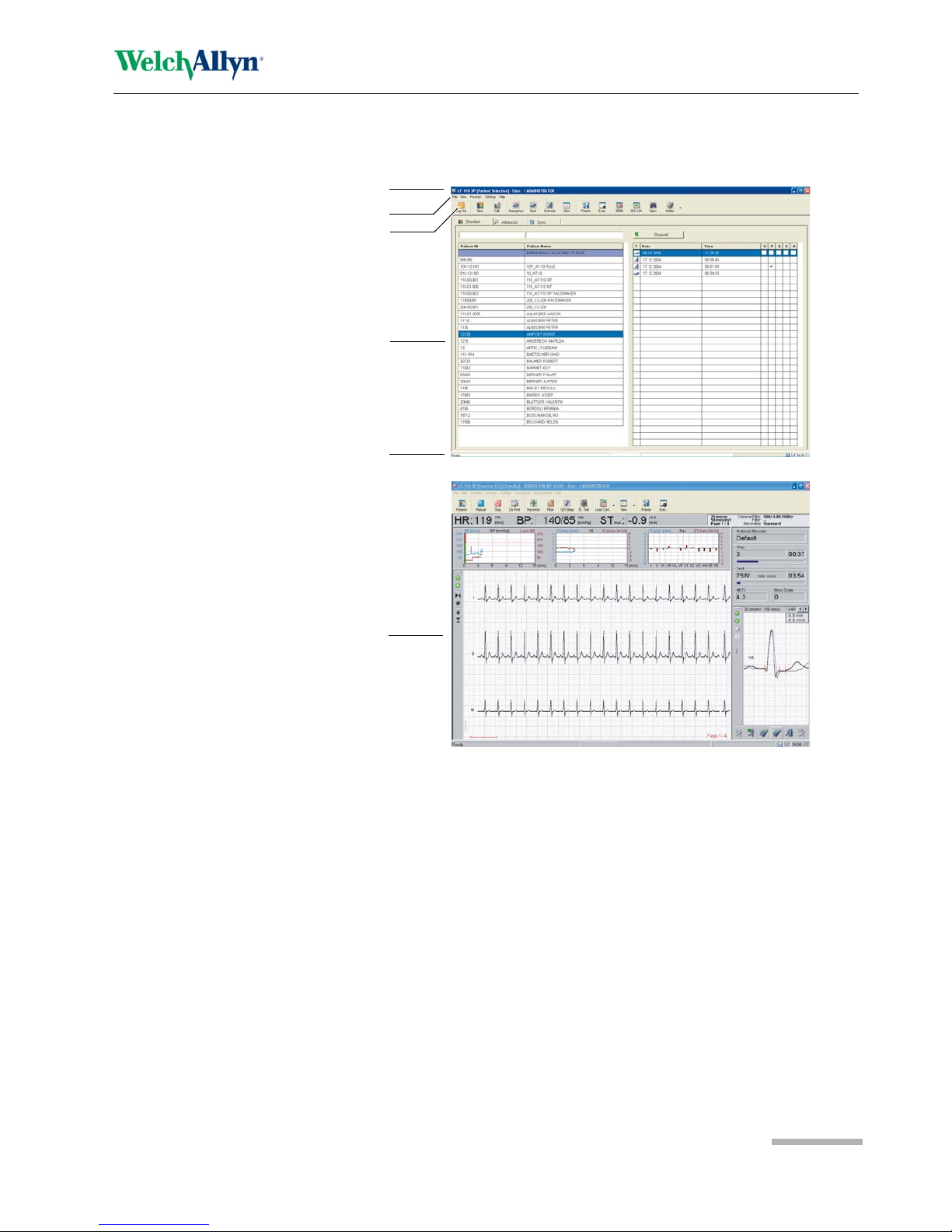
2.8 The Display
The display will vary according to the current task being carried out. In all screens
however, the top, middle and bottom areas display the same information groups. The
following gives examples of the patient screen and the exercise acquisition screen.
(1) Header line - the top line gives general information as follows:
– current screen type (resting, exercise, patient, etc.)
– patient name and number (acquisition screen only)
– the user, and the user login level .
– Menu line - below the header are the menu options.
(2) Menu Line - the menu options will vary according to the screen displayed and
the user login level.
(3) Function icons - these change according to the screen displayed, system set-
tings and the user login level.
(4) Data area - main data area according to the screen selected.
– in the patient screen (4a) this area displays the database information and
includes all stored patients and associated recordings.
– In the data acquisition screens (4b), this area displays the real time data.
– In the view screens (not shown), this area displays the recorded data.
(5) System Information
Example of the Patient Screen
Example of an aquisition Screen
(exercise)
1
3
4a
5
4b
2
3 Function Keys
3.1 Function Key Table
Page 18
Art. no.: 714095 rev.: b
3 Function Keys
3.1 Function Key Table
Patient Screen Recording Screens View Screens
Function Key Resting ECG Exercise ECG Resting ECG Exercise ECG
F1
<Ctrl> F1
Start
Emergency
Acquisition
Screen
F2
<Shift> F2 Edit Patient Edit Patient Edit Patient Edit Patient Edit Patient
<Ctrl> F2
Start Resting
Acquisition
Screen (with
selected
patient)
F3
Start Manual
Printout
Start Manual
Printout
<Ctrl> F3
Start Exercise
Acquisition
Screen (with
selected
patient)
F4
Stop Manual
Print
Stop Manual
Print
F5
Autostart
(Recording)
F6 Filter Filter Filter Filter
<Shift>F6 center Signal center Signal
F7
Start/Begin/
Recovery
F8
F9
F10
Esc
PgDn PgDn
Previous lead
group
Previous lead
group
Previous lead
group
PgUp PgUp Next lead group Next lead group Next lead group
up (arrow) up Previous lead Previous lead Previous lead Previous lead
down (arrow) down Next lead Next lead Next lead Next lead
left (arrow) J-point - J-point - / scroll
right (arrow) J-point + J-point + / scroll
Page 19
Art. no.: 714095 rev.: b
Operation 4
Service handbook CP300 Start-up and Initial Preparation 4.1
4 Operation
4.1 Start-up and Initial Preparation
4.1.1 Location
• Do not keep or operate the unit in a wet, moist, or dusty environment. Avoid exposure to direct sunlight or heat from other sources.
• Do not allow the unit to come into contact with acidic vapors or liquids.
• The CP300 should not be placed in the vicinity of X-ray or diathe rmy units, large
transformers or electric motors.
4.1.2 Connection of External Cable Assemblies and Ancillary
Equipment
1. Connect the power cable at the rear of the unit. The Mains indicator lamp is lit.
2. Connect the patient cable (side panel).
3. Connect any ancillary and optional equipment (see page 15). These may include
the following:
– Ergometer (analogue or digital) for exercise testing
– External monitor
– Network cable
– External printer
4.1.3 Potential equalization
The potential equalization stud at the rear of the unit is used to equalize the ground
potential of the CP300 to that of all mains powered equipment in the vicinity. Use the
hospital or building common ground. A yellow/green ground cable is supplied as an
option.
Danger of electrical shock. Do not operate the unit if the earth connection is
suspect or if the mains lead is damaged or suspected of being damaged.
To avoid possible interference from the ergometer when carrying out an exercise test,
it is recommended that both the CP300 and the ergometer are connected to the same
common ground.
To prevent the possibility of leakage current when an external printer, external
monitor, or ergo device is connected, always ensure that th e mains lead (with
earth grounding connection), and / or the potential equalization, is attached to the
CP300.

4Operation
4.1 Start-up and Initial Preparation
Page 20
Art. no.: 714095 rev.: b
4.1.4 Switching ON and OFF
The unit is switched on and off with the On / Off key.
4.1.5 Power Supply and Backup Battery Operation
Mains and battery LED Indicators
The LED indicators on the unit casing indicate the power operation as follows:
4.1.6 Isolating the Mains Supply
To isolate the power supply, remove the mains plug from the wall socket.
4.1.7 System and ECG Settings
• The System Settings (time, date, user ID, etc.), and other general and ECG
settings (macros, ergometer, etc.), are found in the System Settings section ( see
page 50).
The unit is operated from the mains supply. When mains is connecte d the mains
indicator is lit.
An internal backup battery is provided for emergency use in the event of a mains
power failure. If a power failure occurs the screen goes blank but the processor
continues to function. The backup battery provides enough power for approximately
15 minutes of use. The Battery indicator is lit when ru nning on battery power and
blinks when the battery capacity is low.
Battery Indicator
Mains Indicator
On / Off Key
Function Battery LED Mains LED
Mains Connected:
Battery Charging •On •On
Battery Full •Off •On
Emergency Battery Working: •On •Off
Battery capacity limited • Blinking • Off
The battery LED also blinks when the unit is shutting d own. This indicates that the
operating system has already closed and the system board is switching off.

Page 21
Art. no.: 714095 rev.: b
Operation 4
Service handbook CP300 Glide Point Controller Operation 4.2
4.2 Glide Point Controller Operation
Only light pressure is required to move the cursor and select items by tapping with the
finger. The glide point controller will not work correctly if excessive pressure is used.
To select any menu item or to confirm a setting, select a function etc., the procedure
is the same.
Selecting an Icon
1. Move finger lightly over the glide point controller to position the cursor (arrow) on
the icon that you wish to select.
2. Lightly `double tap` (same as a double clic k with a mouse) the glide point
controller to select.
Pull down menu item
1. Move finger over the glide point controller - the cursor (arrow) on the screen
moves.
2. Position the cursor on the horizontal menu bar and lightly tap the glide point
controller - further menu items are displayed and can be selected in the same
way.
Right Click Function
The lighter area in the top right corner of the glide pad has the same function as the
`right` button on a conventional mouse.
4.2.1 Connecting a Mouse or Trackball Device
The CP300 can work with an external point and control device. When a mouse or
trackball etc. is connected (to the PS-2 connector on the back panel), the glide point
controller operation is disabled.

4Operation
4.3 Changing the Printing Paper
Page 22
Art. no.: 714095 rev.: b
4.3 Changing the Printing Paper
1. Press the Paper Tray key to open the pap er tray (remove any remaining paper
from the paper tray if replacing paper.
2. Place a new pa per pack into the paper tray with the printed (grid) side facing
upwards and the black paper mark to the top of the unit.
3. Place th e beginning of the paper over the black paper roller on the paper tray
cover.
4. Press the Paper Tray key to return the paper tray in positi on.
5. Press the Stop key to transport the paper to the start position.
Important
The device is delivered without printing paper installed. The thermo-paper is sensitive
to heat, humidity and chemical vapors. The following points apply to both storage, and
when archiving the results.
• Before use, keep the paper in its original cardboard cover. Do not remove the card-
board cover until the paper is to be used.
• Store in a cool, dark and dry area.
• Do not store near chemicals e.g. sterilization liquids.
• In particular do not store in a plastic cover.
• Certain glues can react with the paper - do not attach the printout onto a mounting
sheet with glue.
Welch Allyn can only guarantee perfect printouts when CP300 original chart paper or
chart paper of the same quality is used.
Paper Tray
In / Out
Stop Key

Page 23
Art. no.: 714095 rev.: b
Physical and Functional Overview 5
Service handbook CP300 Physical Overview 5.1
5 Physical and Functional
Overview
5.1 Physical Overview
The CP300 unit is enclosed in a two part, medical standard, molded plastic case.
The top part contains the keyboard and the LCD screen with the base section
containing all the electronics of the unit, the RS-232 interface, the thermal printer, the
paper tray, the battery and mains transformer.
The electronics of the unit are contained on a single double sided printed circuit board,
the main board (MK 17-1). This board is secured on spacers molded in the base
section.
The battery is secured in position in a molded recess accessed from the bottom of the
units, and the mains transformer is secured on spacers above the printed circuit
board.
The thermal printer is mounted on spacers mold ed to the base and the paper tray
motor mounted in a similar way.
Exploded views of the unit are given in the Construction Drawings section at the end
of this book (see page 75).
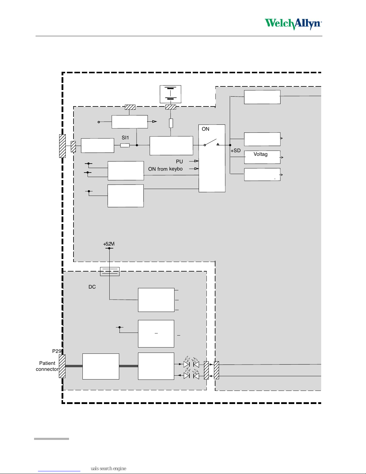
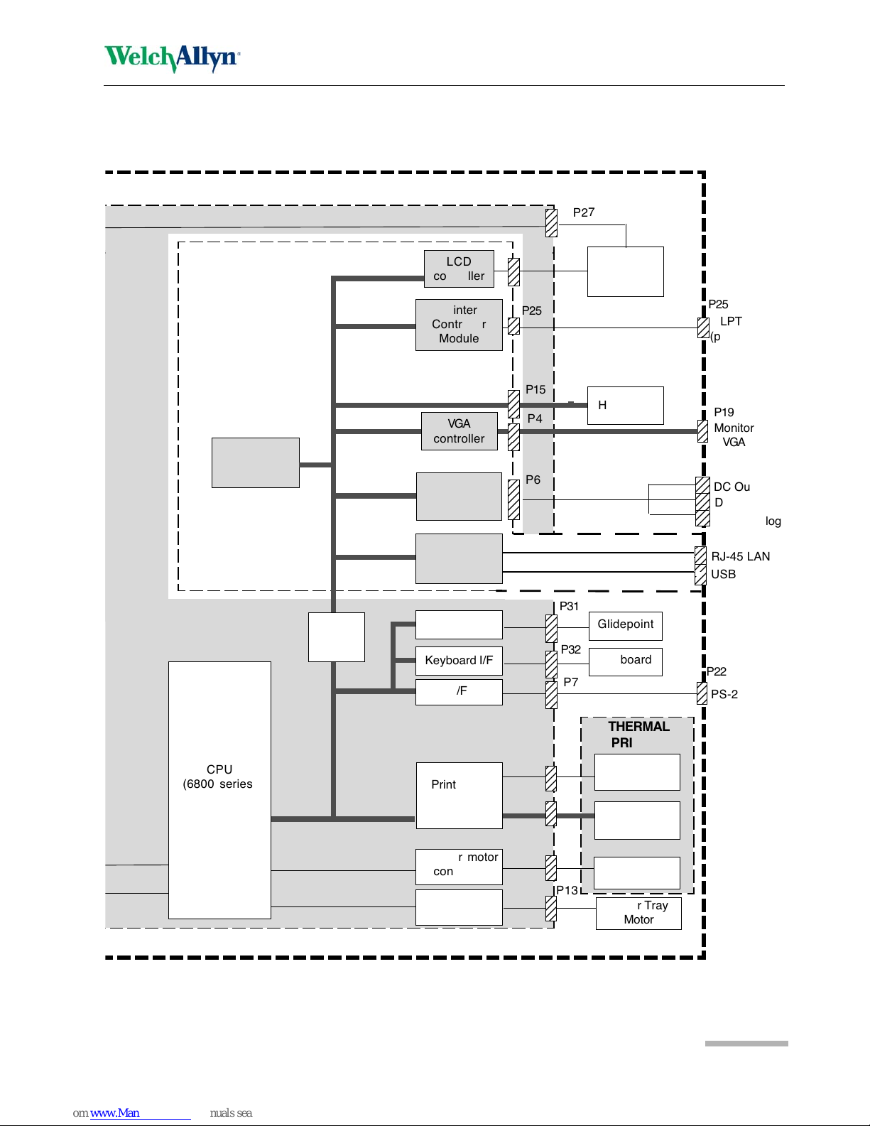
5.2 Functional Overview
The CP300 has a PC architecture, including standard expansions like a network
connection and USB ports, etc. The electronics of the CP300 including the power
supply, is contained on a single Main Board (MK 17-1), which contains a ' piggy back'
PC single board controller. The electronics of the CP300 are EMC shielded.
The ECG board provides isolated patient connection and initial processing of the ECG
signals.
The operating system in the CP300 is Windows® NT or XP. The user interface, all
settings, graphical presentations etc. are based on Windows®. The evaluation of the
ECG data, control of the printer and other functions are realised on the Welch Allyn
ECG processor card with its own 68331 microprocessor system. The systems
communicate with each other via dual port RAMs.
Interconnection and EMC drawings are given in the Construction Drawings section at
the end of this book (see page 78).
5 Physical and Functional Overview
5.2 Functional Overview
Page 24
Art. no.: 714095 rev.: b
-5Vi
+2Vi
+5Vi
-5Vi
-10Vi
MUX
Input ampli-
fier and filter
2
3
2
3
2
3
2
3
2
3
2
3
2
3
Patient
connector
P29
+5.2Vi
DC - DC
converter
Patient
Isolation
(4kVrms)
ECG Board
MK 16-2
DC - DC
converter
reference
voltage
Signal
multiplexer
(PWM)
Overvoltage
protection
Undervoltage
protection
Rectification
Voltage sense
+SD
+US
+5.2V
+24V
Mains/
Batt
LED
Mains
connector
SI1
AT-110
Voltage
regulator
Switching
voltage reg.
+SD
ON / OFF
control
Battery charger &
voltage regulator
21.6 V
Battery
+U
P10
P32
(part)
+Batt
OFF from CPU
ON from keyboard
SI2
Voltage
regulator
Power rail
stabilisation
Main
Board
MK 17-1
LCD power
supply
+5V ref
+5.2V
+24V
2
3
2
3
2
3
2
3
2
3
2
3
2
3
2
3
2
3
2
3
P30
P30
P18
2
3
2
3
2
3
2
3
2
3
2
3
2
3
CTRL
CP-300
Page 25
Art. no.: 714095 rev.: b
Physical and Functional Overview 5
Service handbook CP300 Functional Overview 5.2
Note: The connector designations given here are liable to change.
LCD screen
RJ-45 LAN
2
3
2
3
2
3
2
3
2
3
2
3
DC Out
Ergo Analog
USB
12
12
12
12
12
Keyboard I/F
Print head
controller
Stepper motor
controller
Paper mark
detector
Thermal print
head
Printer motor
P12
P14
P11
12
12
12
12
12
PC Single Board
Computer
D/A Conv.
USART
12
12
12
12
12
I/F
2
3
2
3
PS-2
2
3
2
3
2
3
2
3
2
3
2
3
2
3
2
3
2
3
2
3
2
3
Monitor
VGA
VGA
controller
2
3
2
3
2
3
Hard Disc
CD ROM
2
3
2
3
2
3
2
3
2
3
LPT
(printer)
PC
Interface
P28
12
12
12
12
12
Glidepoint I/F
2
3
Printer
Controller
Module
LCD
controller
2
3
2
3
2
3
P27
P25
P25
P15
P4
P19
P6
P26
P8
P3
P17
P31
P32
P7
THERMAL
PRINTER
Motor
controller
Paper Tray
Motor
P13
Data In
Keyboard
Glidepoint
P22
CPU
(6800 series)
CPU
(Pentium)

6 Functional Checks
6.1 Service interval
Page 26
Art. no.: 714095 rev.: b
6 Functional Checks
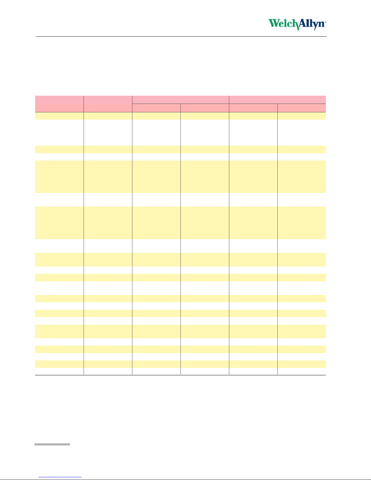
6.1 Service interval
The device must be checked at regular intervals. The test results must be compared
with the results following and be documented.
The following table gives information about interval and competence of maintenance
which can be required.
Interval Service Responsible
Every 6 months
• Visual inspection of the unit and cables (see page 29).
• General unit integrity check (see following).
User
Every 12 months
• The visual, general, measuring and calibration tests and checks according to the checklist at the end of this book (see page 81).
By Welch Allyn authorized
technician
Every 12 months
a
a. The time interval for the electrical safety tests is a guideline and can vary according to local and country specific directives and according to unit use. For example when a unit is used intensively, safety checks should be carried out more often. When a unit is used
less intensively, the safety check period can be longer. In addition the safety test must be carried out in the following circumstances:
-If a unit is dropped, receives any large jolt or knock or is subject to severe vibration, etc.
-If a unit has been subject to strong radiation or electrical shock, etc.
-When a unit has been repaired or serviced that requires the case to be opened.
-Additionally, a safety test can be carried out at any time if the unit isolation is suspected of being inadequate.
• Electrical safety tests according to either:
– IEC 60601-1, (see page 37), or
– EN 62353:2005, or
– Local directives
b
b. The two directives detailed here are standard specifications for reference. Local and country directives for safety testing of medical
devices must be adhered to and take precedence.
By Welch Allyn authorized
technician
 Loading...