

Welch Allyn Connex CS Install Manual

Welch Allyn Connex
Server
®
CS
Install Guide
Platform or Virtual Server

Welch Allyn, Inc.
4341 State Street Road
Skaneateles Fall, NY 13153-0220 USA
www.welchallyn.com
Regulatory Affairs Representative
Welch Allyn Limited
Navan Business Park
Dublin Road
Navan County Meath
Republic of Ireland
ii Welch Allyn Connex CS Server Install Guide
© 2014 Welch Allyn. All rights are reserved. To support the intended use of the product described in this publication,
the purchaser of the product is permitted to copy this publication, for internal distribution only, from the media
provided by Welch Allyn. No other use, reproduction, or distribution of this publication, or any part of it, is permitted
without written permission from Welch Allyn.
Welch Allyn assumes no responsibility for any injury to anyone, or for any illegal or improper use of the product, that
may result from failure to use this product in accordance with the instructions, cautions, warnings, or statement of
intended use published in this manual.
Welch Allyn and Connex are registered trademarks of Welch Allyn.
SQL Server, Visual Studio, Windows and Windows Server are all registered trademarks of Microsoft.
For patent information, please visit www.welchallyn.com/patents.
Software in this product is Copyright 2014 Welch Allyn or its vendors. All rights are reserved. The software is
protected by United States of America copyright laws and international treaty provisions applicable worldwide. Under
such laws, the licensee is entitled to use the copy of the software incorporated with this instrument as intended in the
operation of the product in which it is embedded. The software may not be copied, decompiled, reverse-engineered,
disassembled, or otherwise reduced to human-perceivable form. This is not a sale of the software or any copy of the
software; all right, title, and ownership of the software remain with Welch Allyn or its vendors.
For information about any Welch Allyn product, contact Welch Allyn Technical Support
(www.welchallyn.com/support), visit (www.welchallyn.com/about/company/locations.htm)
This device complies with Part 15 of the FCC rules and with the rules of the Canadian ICES-003. Operation is subject
to the following two conditions: (1) This device may not cause harmful interference and (2) this device must accept
any interference received, including interference that may cause undesired operation.
Caution! Changes or modifications not expressly approved by Welch Allyn could void the purchaser’s authority to
operate the equipment.
DIR 20012794 Ver. F This manual applies to 901066 Monitoring Station

Contents
Contents ............................................................. iii
0 Quick Reference Guide .............................................. 1
Overall Sequence .................................................. 1
Install Connex Server ................................................ 2
Milestone Checklist ............................................... 2
1 Introduction ....................................................... 4
About this manual .................................................. 4
Scope ........................................................... 4
Responsibilities .................................................... 4
Related Documents ................................................. 5
Symbols used in this manual .......................................... 5
Required Equipment ................................................ 5
Definitions ........................................................ 6
2 Overview and Planning .............................................. 8
Overview ......................................................... 8
Planning for the Install ............................................... 9
Site Preparation and Inspection ..................................... 10
Equipment Staging and Inspection ................................... 10
3 General Setup .................................................... 14
Install Hardware Connex server ....................................... 14
Four post rack / data cabinet mounting ................................ 14
Two post relay rack mounting ...................................... 14
General Setup, hardware ............................................ 15
4 Connex Server Startup .............................................. 16
Before you begin... ................................................. 16
Networked environment (Client / Server) considerations ................... 16
Warm Spare station considerations .................................. 16
Server boot up screens ............................................. 17
Confirm Connex Server operational state ................................ 19
Confirm communication with central stations .............................. 21
5 HL7 Interface Configuration .......................................... 22
Confirm Connex CS Admin tools configuration ............................. 22
Importing a customer specific Corepoint NIX file ........................... 24
Commit and activate NIX file changes ................................ 28
Configure IP address and ports for EMR connections ..................... 30
Restart connections after changes ................................... 33
Corepoint service .................................................. 36
Confirm communication with EMR ..................................... 37
6 General Connex CS Configuration ..................................... 40
Configure alarm gateway on server ..................................... 40
Configure AGS Input / Output connections ............................. 41
Configure AGS Priority filter ........................................ 42
Configure Clinician Authentication...................................... 43
Multiple Security Providers ........................................ 44
View Clinician Authentication settings ................................. 44
Configure for use with Connex Database .............................. 46
Configure for use with Active Directory ................................ 49
Order the security providers ........................................ 53
Delete a security provider ......................................... 53
Configure auto discharge settings ................................... 54
iii

iv Welch Allyn Connex CS Server Install Guide
ADT auto discharge settings ....................................... 55
Auto discharge settings for confirmed patients .......................... 56
Late ADT settings ............................................... 57
7 Final Steps ...................................................... 59
Final Steps ...................................................... 59
Backup Connex CS users and configuration .............................. 59
Backup Corepoint configuration - create a NIX file .......................... 61
Backup Corepoint HL7 License ..................................... 64
Disconnect peripherals .............................................. 65
A Troubleshooting ................................................... 67
Front Panel LED information.......................................... 67
Server Startup .................................................... 68
Connex database restore ............................................ 69
Stop Services, Scheduled Tasks, and close the CS Application .............. 69
Restore the database from backup ................................... 70
De-provision the Restored Database ................................. 74
Reinstall the database on the central stations ........................... 74
Restart the Data Sync Service and Wait for Completion of the Initial Sync Operation77
Restart Services, Scheduled Tasks, and Open the CS Application. ........... 77
Special circumstances... .......................................... 77
Connex database re-installation ....................................... 78
B Updating BIOS ................................................... 83
Preparation for BIOS update.......................................... 83
Update BIOS installation ............................................ 84
Post update BIOS settings changes .................................... 86
General navigation in the BIOS utility ................................. 86
Troubleshooting BIOS updates ........................................ 93
BIOS recovery process ............................................. 94
Clearing the BIOS password.......................................... 95
Clearing the BIOS CMOS ............................................ 96
C Hardware Server Mounting Solutions ................................... 97
Install server with slide rails into a four post cabinet ......................... 97
Install outer member into cabinet .................................... 97
Attach inner slide member to server chassis ............................ 99
Insert server into cabinet using the slide rails .......................... 100
To remove server installed with slide rails ............................... 101
Install server with shelf kit into a two post relay rack ........................ 102
Install mounting flanges onto shelf .................................. 102
Attach shelf to rack posts......................................... 103
Install server onto shelf .......................................... 104
D Install a Replacement Disk Drive ..................................... 105
Remove a hard disk drive ........................................... 105
Install a hard disk drive ............................................ 106
E Connect to Server via BMC Console ................................... 107
F Network change and configuration .................................... 111
Network IP change overview ........................................ 111
Client Server deployment ........................................... 112
If the IP address of the Connex server changes ........................ 112
If IP Address of the Connex Workstation Changes ...................... 117
If IP Address of the EMR Server Changes ............................ 117
If IP Address of the 3rd Party Alarm Server Changes .................... 119
Standalone Deployment ............................................ 121
If IP address of standalone Central Station system changes ............... 121

If IP Address of the 3rd Party Alarm Server Changes ..................... 122
Kiosk deployment ................................................ 124
If the IP address of the Server changes .............................. 124
Connex Proview Installation ......................................... 125
If the IP address of the Service Changes ............................. 125
G Printer, Date & Time configuration .................................... 126
Add a Customer Supplied Printer ..................................... 126
Install from an executable file (.exe) ................................. 126
Install from a setup info file (.inf).................................... 126
Change Date and Time ............................................ 127
H Moving from Test to Production ...................................... 130
Assumptions .................................................... 130
Preparation ..................................................... 130
Create a database restore point ...................................... 131
Clearing test data from the WADB database ............................. 132
Configure HL7 connections, if required ............................... 136
Confirm Connex server operation, client-server only ..................... 137
Synchronize central stations, client-server only ........................... 137
Restart after synchronization is complete ............................... 140
Finalizing the Environment .......................................... 140
Troubleshooting test to production issues ............................... 141
I Virtual Connex Server Field Installation ................................. 142
Procedure: ..................................................... 142
v

vi Welch Allyn Connex CS Server Install Guide

1
0
The quick reference guide provides a high level sequence overview to the process of installing a
Connex CS system and milestone checklist to measure progress. Complete details can be
referenced within this document as needed.
Quick Reference Guide
Overall Sequence
1. Unbox, inventory, and stage all equipment.
2. Install Connex server hardware (if applicable) first.
a. Alternately, provide the virtual Connex server appliance (USB flash drive media) to
the customer for installation on their virtual server (if applicable). Appendix I “Virtual
Connex Server Field Installation” provides an overview of the virtual server
installation process.
b. Import Corepoint configuration file / configure inbound & outbound HL7 connections
(if applicable).
c. Establish TeamViewer remote access to Connex server to minimize time in the data
center.
3. Install Central Station(s).
4. Install Warm Spare station (if applicable).
5. Confirm basic system operation.
6. Install a Repeater Display (if applicable).
7. Perform other configuration changes (if needed).
a. Import configuration file for custom data (if needed).
b. Configure Alarm Gateway Service (if needed).
c. Configure device clinician authentication (if needed).
8. Export (backup) system configuration when changes are complete.
9. Verify system (Central Stations, Warm Spare, Connex server, and Device communication).
10. Repeat steps 1 to 9 for a Test Network, including Test Connex server and Test Central
Station (as applicable).
11. Perform customer admin training with technical team (Biomed, IT, etc.).
Complet
e?
Task
No.
Milestone
Applies to
virtual Connex
Server
installation?
Install slide rails into 4 post equipment cabinet/rack.
OR
Install shelf mount into 2 post equipment rack (if applicable.
No. Skip this
step.
Install server into slide rails.
OR
Install server onto shelf mount (if applicable).
No. Skip this
step.
Connect USB keyboard and mouse.
OR
Connect customer provided terminal/KVM cabling (If applicable).
No. Skip this
step.
Connect network cables.
Note: LAN #1 designated for comms with Connex CS systems and patient
monitors.
Note: LAN #2 designated for comms with facility EMR application (if
applicable).
No. Skip this
step.
Connect video cable to a temporary display OR connect customer provided
terminal/KVM cabling (if applicable).
Connect power to all components and turn on.
No. Skip this
step.
Provide media containing the Virtual Connex server to IT staff for installation (if
applicable).
Work with IT staff to start the Connex server at the end of installation.
Yes.
Confirm boot and startup sequence of Connex server (hardware or virtual).
Confirm basic server operation.
Confirm TeamViewer access.
Yes.
Import customer specific NIX file and configure customer connections (if
applicable).
Confirm status of Corepoint connections: (Inbound ADT/Outbound confirmed
ORU/Outbound unconfirmed ORU).
Yes.
Complete installation of all Central Stations and Warm Spare station (if
applicable).
Refer to Connex CS Central Station Install Guide for instructions.
Yes.
Update configuration as needed.
Note: A reboot is required when adding licenses, updating Covered
Areas, updating the Master Bed List, or updating NRS settings.
Export (backup) configuration and users file.
Yes.
Complete all tests as applicable to verify the Connex server installation.
Refer to the Connex CS Install Verification Guide for instructions.
Yes.
2 Quick Reference Guide
Install Connex Server
Milestone Checklist
The following table includes some high-level milestones when installing a hardware Connex
server and may be used as a checklist to assist in tracking progress.

3

4 Introduction
1
Introduction
About this manual
This Connex CS Server Install Guide provides information needed to plan and perform the
installation of the Connex server and it’s peripheral components. The Connex server is an
accessory to the Connex CS Central Station. This information describes how to:
Plan and stage the hardware Connex server
Install and configure the Connex server (hardware or virtual)
Confirm basic proper system operation
Perform configuration of the Connex server to customize the environment per need.
Scope
This guide includes information for installing the Connex server, hardware or virtual, and
applicable peripheral equipment including:
Keyboard / Mouse
Video Display
Laser Printer
For installing other items not mentioned above, including the Connex CS Central Station
equipment, refer to Related Documents.
Responsibilities
The processes described herein are to be completed by an authorized Welch Allyn representative
or qualified service agent responsible for the central station.
Familiarity with Windows operating system is assumed. Windows experience assumes familiarity
with basic commands, navigating directories, editing files, modify or restore the database.
Welch Allyn Service Engineering is responsible for the creation and maintenance of this
document.
Document
Number
Document Title
20012793
Connex CS Central Station Install Guide
20012800
Connex CS Install Verification Guide
80017306
Connex CS Customer Project Req. Form
80018045
80018210
Connex CS Pre-Install Checklist
Connex CS Central Station & Server Admin Guide
WARNING Warning statements identify conditions or practices that could result in
personal injury.
CAUTION Caution statements identify conditions or practices that could result in
damage to the equipment or property.
Note
Notes provide additional important information. The content of the note may not
be contained elsewhere in the document.
Related Documents
Symbols used in this manual
5
Required Equipment
If installing a hardware server, the person performing this installation should have the following
tools and supplies;
One pair of 5 inch (12.7 cm) diagonal cutting pliers, electronic, narrow jaw for cable dressing
as needed.
One #2 Phillips Screwdriver, for mounting Server in equipment rack as required.
Approximately 10 each 8 inch (20 cm) nylon cable ties or equivalent for cable dressing as
needed.
Approximately 10 each 15 inch (38 cm) nylon cable ties or equivalent for cable dressing as
needed.
Quantities shown above are typical. The actual install project may consume more or less
depending on size or complexity.

AGS
Alarm Gateway Service, a licensable feature which provides alarm
messages in a data stream to a 3rd party system.
BMC
Baseboard Management Console, a console that runs on the server
which provides autonomous monitoring and recovery of critical server
functions.
BIOS
Basic Input / Output System, the boot firmware program that controls
the server on startup until the operating system takes over. Also
performs POST functions and error reporting.
Client-Server
A topology in Connex CS with a central station PC (client) and a
Connex server (hardware or virtual server). In the client-server
model, data is replicated between the client and the server via the
Welch Allyn Connex Data Synchronization Service.
CPU
Central Processing Unit, a desktop PC in the case of Connex CS.
Component
A major subassembly of the central station or network (e.g. CPU,
Video Display, Printer, Ethernet Switch, etc.).
EMR
Electronic Medical Record, the record system maintained by the
facility with patient information and data, including vital signs.
ESXi
A VMWare virtual environment
FRUSDR
Field Replaceable Unit / Sensor Data Record, contains a hardware
list that is used by the BMC in monitoring and managing server
health.
HDD
Hard Disk Drive, the internal media which contains the operating
system along with all software required to run the server and installed
applications
HIS
Hospital Information System, the network in use by the facility that
supports network communication with various systems and devices,
including Connex CS central station, Connex server, and devices.
Installation
The on-site process for installing the hardware or virtual server,
network infrastructure, and system configuration at the customer’s
location of business.
LAN
Local Area Network, a network of computers connected together in a
local environment. Typical communication includes standard Ethernet
protocols.
PDR
Project Data Repository, an electronic archive of content for a
customer specific project, from pre-sales to installation phases.
Examples of documents in the PDR may include the completed forms
of the Connex CS Customer Project Req Form, Pre-Install
Checklists, Statement of Work documents, etc.
POST
Power On Self Test - An integrity check within the CPU and/or device
to ensure that all expected components are present and working (e.g.
memory tests).
RMM4
Remote Management Module 4, an out-of-band management
interface included with the hardware server which provides access
via the network to remotely manage and control the server
independent of MS Windows Server operating system. Also see BMC
for related information.
6 Introduction
Definitions

Upgrade
On-site service activity to enhance or add functionality to a device or
system. An upgrade can be accomplished with changes to hardware,
software, configuration, or combinations of all three.
UPS
Uninterruptable Power Supply, a unit which provides battery back-up
power for connected devices.
Virtual Connex Server
A server instance which has been virtualized to an appliance form
(includes Operating System, Connex Applications, and Database)
and installed within the customer’s Virtual Server environment.
7

8 Overview and Planning
2
Overview
The Connex Central Monitoring Station (central station) is intended to be use by clinicians for the
central monitoring of neonatal, pediatric, and adult patients in health care facilities.
In addition to the central monitoring of patient data, alarms and alerts, the Connex software can
include optional modules to provide extended recording of patient data, including full disclosure.
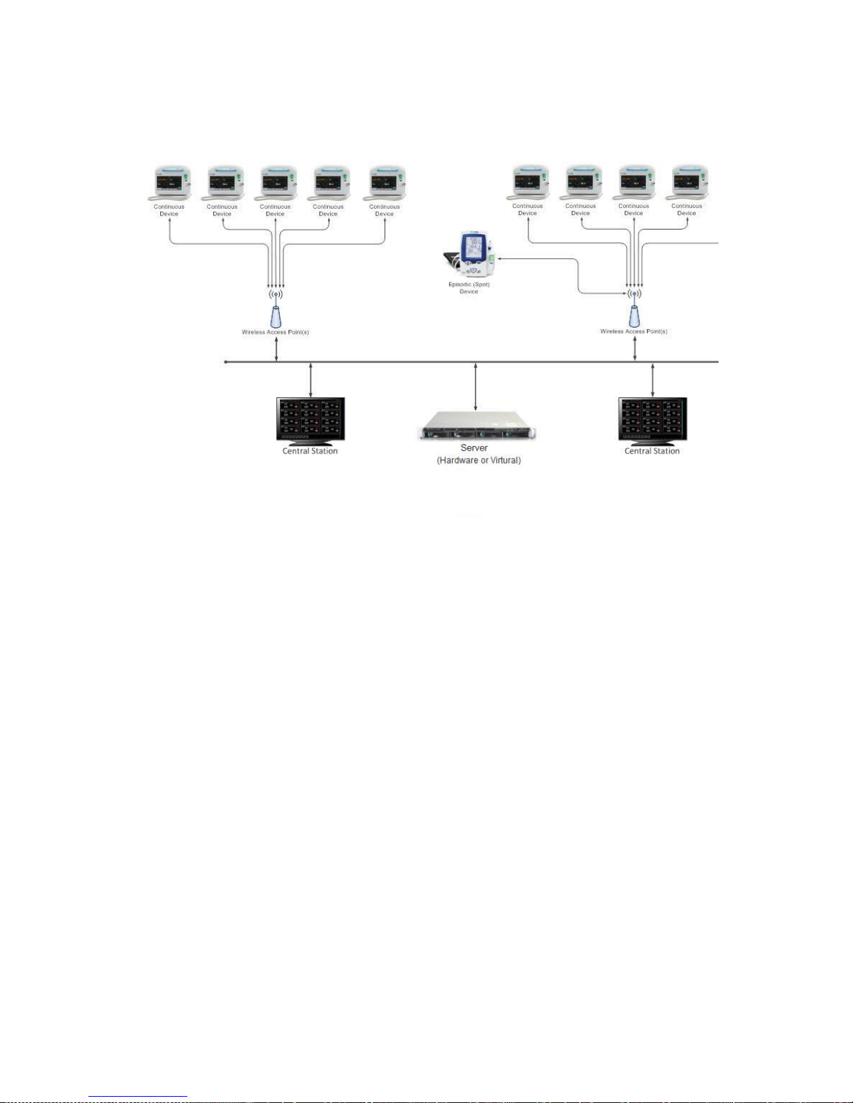
The Connex CS system consists of a central station that receives and displays information from
connected devices. In this configuration, continuous and episodic devices communicate over the
network to the central station. The central station contains all of the software needed to monitor
patients’ continuous parameters and episodic data on a single computer.
The central station also monitors connected continuous devices for proper operation, and
displays an alarm if a continuous monitor stops working or is improperly disconnected.
Multiple central stations may be installed in a shared environment with a server, hardware or
virtual based, providing a central data repository for all information. In addition, the server may
also be used to support integration with the facilities HIS to share patient information and data.
A high-level topology with multiple central stations and a server is shown in Figure 2-1: “Multiple
Connex CS conceptual model” below. Although all devices are shown with wireless
communication, a wired-networking model may also be use.
Overview and Planning
9
Note
The most current information for a customer specific project will be located in the
project data repository (PDR).
Figure 2-1: Multiple Connex CS conceptual model
Planning for the Install
To install the server and peripheral components you will:
Verify that the site is ready for the installation
Check and stage all hardware components.
Set up and install hardware Connex server components (if applicable).
Deliver media containing the Virtual Connex server to IT staff for installation to
customer’s Virtual Server (if applicable)
Configure Connex server components.
Depending on the size of the system and the customer readiness, the install could take from 2 to
4 hours.
As most central stations and Connex servers are uniquely configured to the customer’s
requirements, always refer to the accompanying documentation which includes a Connex CS
Customer Project Req. Form detailing the planned implementation.
Install system components as described within the Connex CS Customer Project Req. Form.

Note
The documentation package is typically included in a large envelope within the
CPU shipping box, and contains important reference information that was used to
configure systems in the manufacturing process. DO NOT MISPLACE THESE
DOCUMENTS. Make working copies for reference.
WARNING It is strongly recommended that the hardware Connex server is
installed with a redundant power source, such as an uninterrupted power supply
(UPS) capable of supporting at least 500 watts. The facility is responsible to
provide 100 percent reliable power to all components. The hardware Connex
server will only work with reliable AC power.
10 Overview and Planning
Site Preparation and Inspection
First locate the equipment and the accompanying documentation package.
Confirm that all items have been completed per the Connex CS Pre-Install Checklist, if
applicable, including installation of all electrical service, data cabling, and fixture installations (e.g.
4-post equipment rack, etc.).
The hardware Connex server is designed to be installed within a 4-post equipment rack, and will
consume 1U of rack space. If space within a 4-post equipment rack is not available, alternate
mounting solutions can be made using a 2-post equipment rack with a shelf mounting kit.
Typically it is expected that the hardware Connex server will be installed in a data center type of
environment, along with other server hardware. These should have all been prepared prior to
your arrival at the facility.
1. Locate the assigned network jacks for the hardware Connex server.
a. Ensure that the distance will be reachable using standard network patch cable lengths of
five or ten feet.
2. Locate available AC Power outlets.
Equipment Staging and Inspection
1. All components should have arrived prior to your arrival on-site, however some parts may
need to be special ordered and shipped while you are installing the system (e.g. special
cables). Contact the field Project Coordinator, via Welch Allyn technical support as
necessary.
2. Visually compare the components received against the Sales Order contained within the
documentation package to ensure that all of the proper components have arrived.
3. As you unbox each component, visually inspect for damage which may have been sustained
during shipment.
4. Contact the field Project Coordinator, via Welch Allyn technical support as necessary, to
report damaged or missing components.
5. Move the following components to the hardware Connex server location (or temporary setup
location) if applicable:
Hardware Connex server
Rail kit
Keyboard / Mouse
Power Cables
11
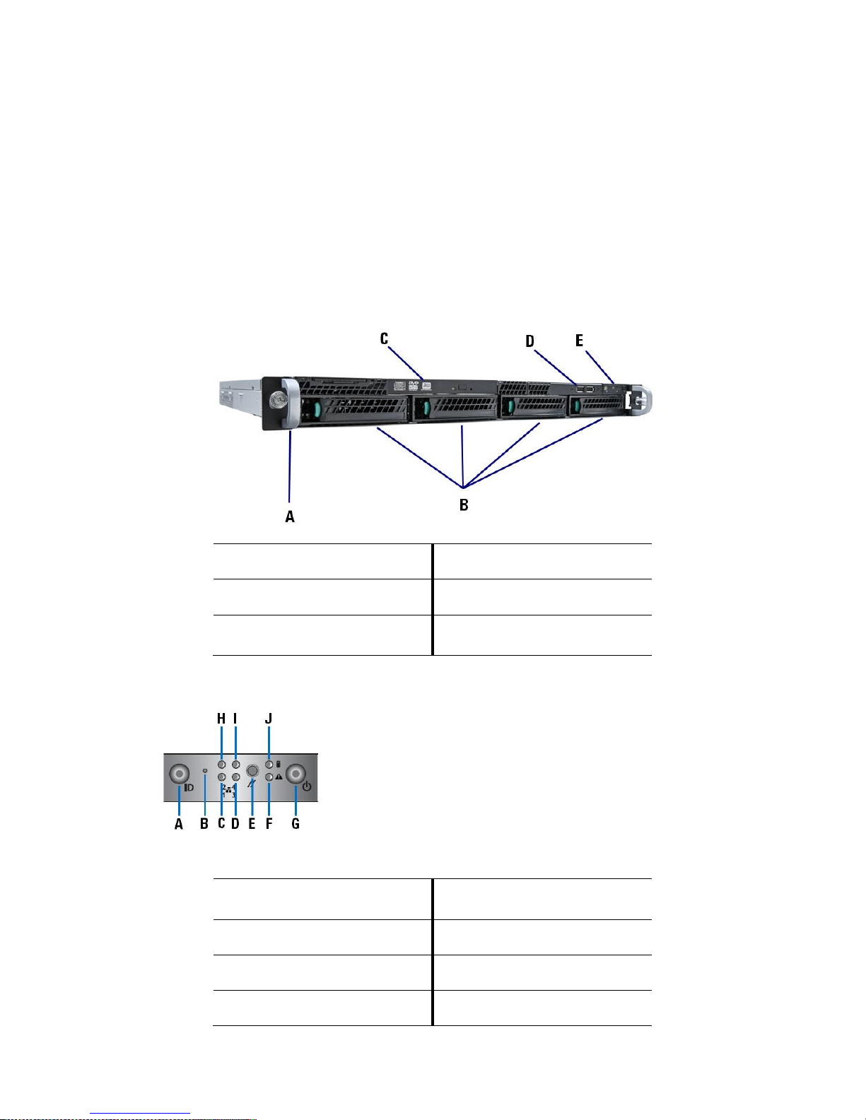
A
Rack handles (2)
D
USB Ports
B
Hard drive bays
E
Front panel controls
C
Slimline optical drive
(optional)
A
Unstuffable ID button with
ID LED
F
Status / Fault LED
B
NMI Button (recessed)
G
Power Button with LED
C
LAN1 LED
H
LAN2 LED
D
LAN3 LED
I
LAN4 LED
Data cables
6. Provide the media containing the Virtual Connex server to the IT staff of the facility if
applicable.
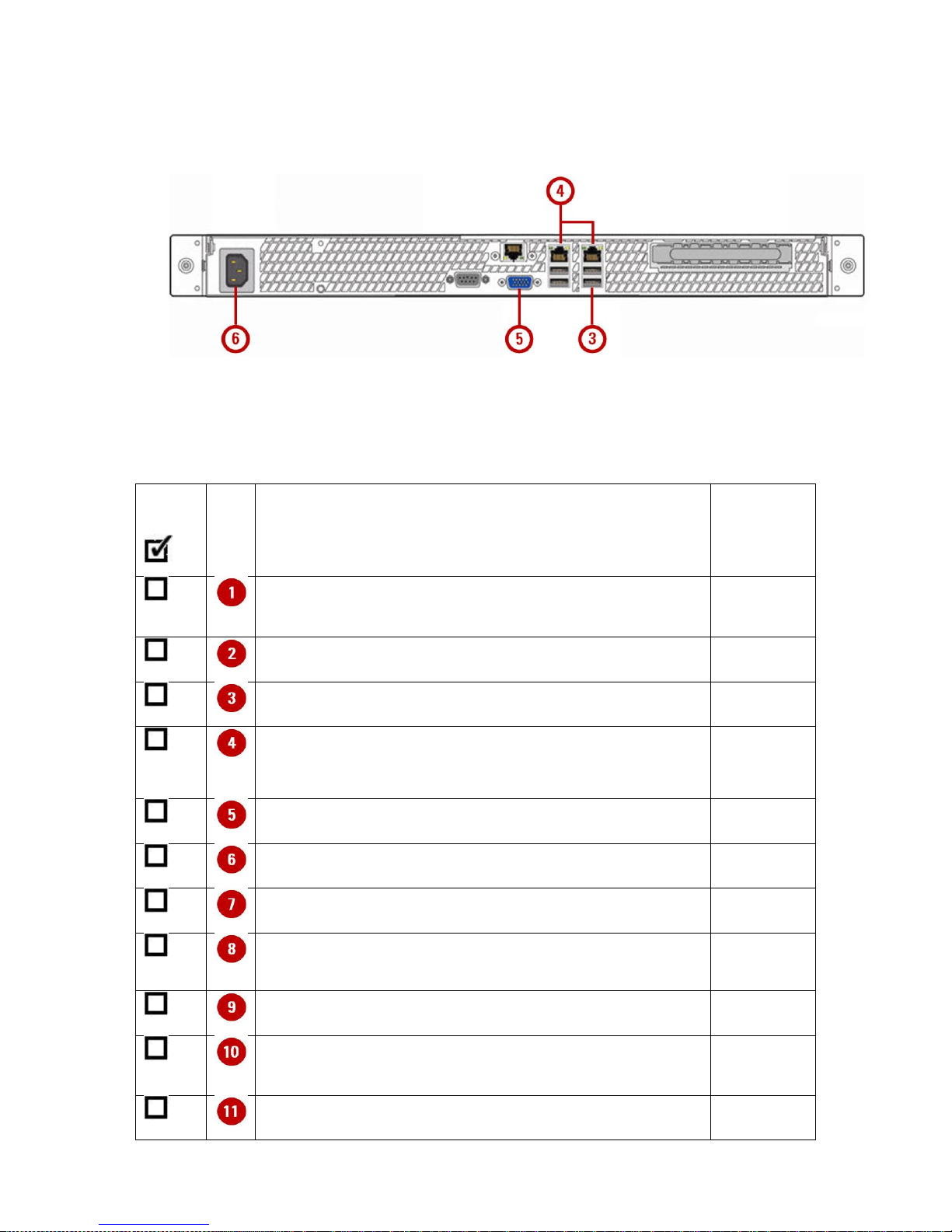
7. For hardware Connex server installations, review Figure 2-2: “Hardware Connex server front
panel features and connectors”, Figure 2-3: “Hardware Connex server front panel controls”,
and Figure 2-4: “Hardware Connex server rear panel connectors”.
8. Familiarize yourself with the location of all features, controls, indicators, and connectors on
the hardware Connex server.
Figure 2-2: Hardware Connex server front panel features and connectors
Figure 2-3: Hardware Connex server front panel controls

E
Reset Button
J
HDD LED
A
AC Power inlet (100 - 240
VAC)
F
PCI Express slot
B
Serial port A
G
Video connector
C
Service Mgmt network
interface (BMC)
H
USB Ports
D
NIC 1 Connector
(10/100/1000 Mb)
I
USB Ports
E
NIC 2 Connector
(10/100/1000 Mb)
12 Overview and Planning
Figure 2-4: Hardware Connex server rear panel connectors

13

14 General Setup
3
General Setup
Install Hardware Connex server
There are several mounting options for mounting the hardware Connex server. The options are
dependent on which equipment rack type is available at the facility. The typical rack configuration
is either a four post rack/data cabinet or a two post relay rack.
Those with four posts or data cabinets should use the slide rails, while the two post relay rack
must use the shelf mounting option. Consult with the Welch Allyn project manager for your install
project for assistance if needed.
Four post rack / data cabinet mounting
The slide rail kit for the server is compatible with equipment racks that meet the following
standards.
Four post structure (mounting at both front and rear). Two post racks are not compatible.
Rack horizontal opening and unit vertical pitch conforming to ANSI/EIA 310-D-1992 or IEC
60927 standards.
Distance between front and rear mounting planes of 610 mm and 915 mm (24 inches to 36
inches).
Clearance depth (to front cabinet door) in front of front rack mounting plane at least 25.4 mm
(1 inch).
Clearance depth (to rear cabinet door) as measured from behind front rack mounting plane at
least 660 mm (26 inches).
Clearance width (between structural supports and cable troughs) between front and rear
mounting planes at least 451 mm (17.75 inches).
The maximum recommend server weight for the slide rails is 59 kg (130 pounds).
See Appendix C “Hardware Server Mounting Solutions” for procedures to install slide rails onto a
four post rack.
Two post relay rack mounting
The shelve mount kit for the server is compatible with two post racks consist of two vertical rails
that meet the following standards.
Clearance width (between structural supports and cable troughs) between front and rear
mounting planes at least 451 mm (17.75 inches).
Clearance depth is variable. The equipment shelve can be configured to mount using a front
mount, a center mount, or a rear mount configuration.
A minimum clearance of 102 mm (4 inches) should be planned beyond the rear server
chassis to accommodate cables.

Note
Only a single USB extension cable may be used for each device. Attaching 2 or
more USB extension cables in series may result in intermittent problems with
input type devices.
WARNING It is strongly recommended that the hardware Connex server is
installed with a redundant power source, such as an uninterrupted power supply
(UPS) capable of supporting at least 500 watts. The facility is responsible to
provide 100 percent reliable power to all components. The hardware Connex
server will only work with reliable AC power.
See Appendix C “Hardware Server Mounting Solutions” for procedures to install shelve mount kit
into a two post rack.
General Setup, hardware
If installing a hardware Connex Server:
1. Locate a flat panel display for temporary use during setup and configuration.
a. Optionally connect a customer supplied KVM server to the server. These may exist in
the data center environment and not require any client software to be installed on the
server.
b. Optionally use the BMC / RMM4 management console to connect to the server over the
network. For additional information, see Appendix E “Connect to Server via BMC Console”.
2. Connect USB devices as follows:
a. Connect the keyboard to one of the USB jacks located on the rear of the server.
b. Connect the mouse to an adjacent USB jack on the rear of the server.
c. Use a single USB extension cable for each device if required for longer distances.
15
3. Connect all network interfaces as follows:
a. Attach an RJ45 type network cable from the server LAN1 port to the customer
designated switch jack. In general LAN1 is used for the CS application interface.
Refer to the Connex CS Customer Project Req. Form, Section B as needed.
b. If needed, attach an RJ45 type network cable from the server LAN2 port to the
customer designated switch jack. In general LAN2 is used for the interfacing with the
hospital EMR application. Refer to the Connex CS Customer Project Req. Form,
Section B as needed.
c. Attach an RJ45 type network cable from the server MGMT port to the customer
designated switch jack. The MGMT port is used for the service management and
remote connections to the BMC and RMM4 console of the server. Refer to the
Connex CS Customer Project Req. Form, Section B as needed.
4. Connect flat panel display to the server HD15 analog video display connector. The display
will only be used during setup and configuration and will be removed for normal operation.
5. Attach the AC power cord to the rear input on the server, and to a customer designated
power outlet.

16 Connex Server Startup
4
Connex Server Startup
Before you begin...
Some additional considerations need to be taken when working in a networked environment.
Depending on the system configuration from manufacturing, a system may be configured as a
networked central station with a shared Connex server, and/or a warm spare station. The station
behavior at startup differs based on the configuration.
Networked environment (Client / Server) considerations
In the networked environment, where there is a Connex server, hardware or virtual, it is preferred
that the Connex server be started first. The Connex server hosts the main database that all
central stations attempt to synchronize with on startup, using the Welch Allyn Connex Data
Synchronization Service.
A central station configured as part of a network (client-server) model will start up with the central
station application and run by itself, but may take much longer during the startup process if the
Connex server is unreachable. The central station may also be running in a degraded mode until
the Connex server is brought online (e.g. ADT services may not be available). Refer to the
Connex CS Central Station Install Guide for additional information and startup behavior for a
central station system.
Warm Spare station considerations
A Warm Spare is part of a network environment, with a Connex sever as well. It is preferred that
the Connex server, hardware or virtual, be started first. Central stations, including a warm spare
should be started after the Connex server is running. Refer to the Connex CS Central Station
Install Guide for additional information and startup behavior for a Warm Spare system.
Note
Internal fans in the server may run at full speed during the boot up process. This
is normal and expected operation.
Note
A virtual drive being reported with a status of Degraded indicates a potential
problem with one of the hard disk drive. Contact Welch Allyn technical support for
additional assistance.
Server boot up screens
If installing a Virtual Connex server, skip ahead to Step 8 at Windows Server startup.
If installing a hardware Connex server, follow all steps below.
1. Press the power button on the right side front bezel control panel of the server to start the
computer.
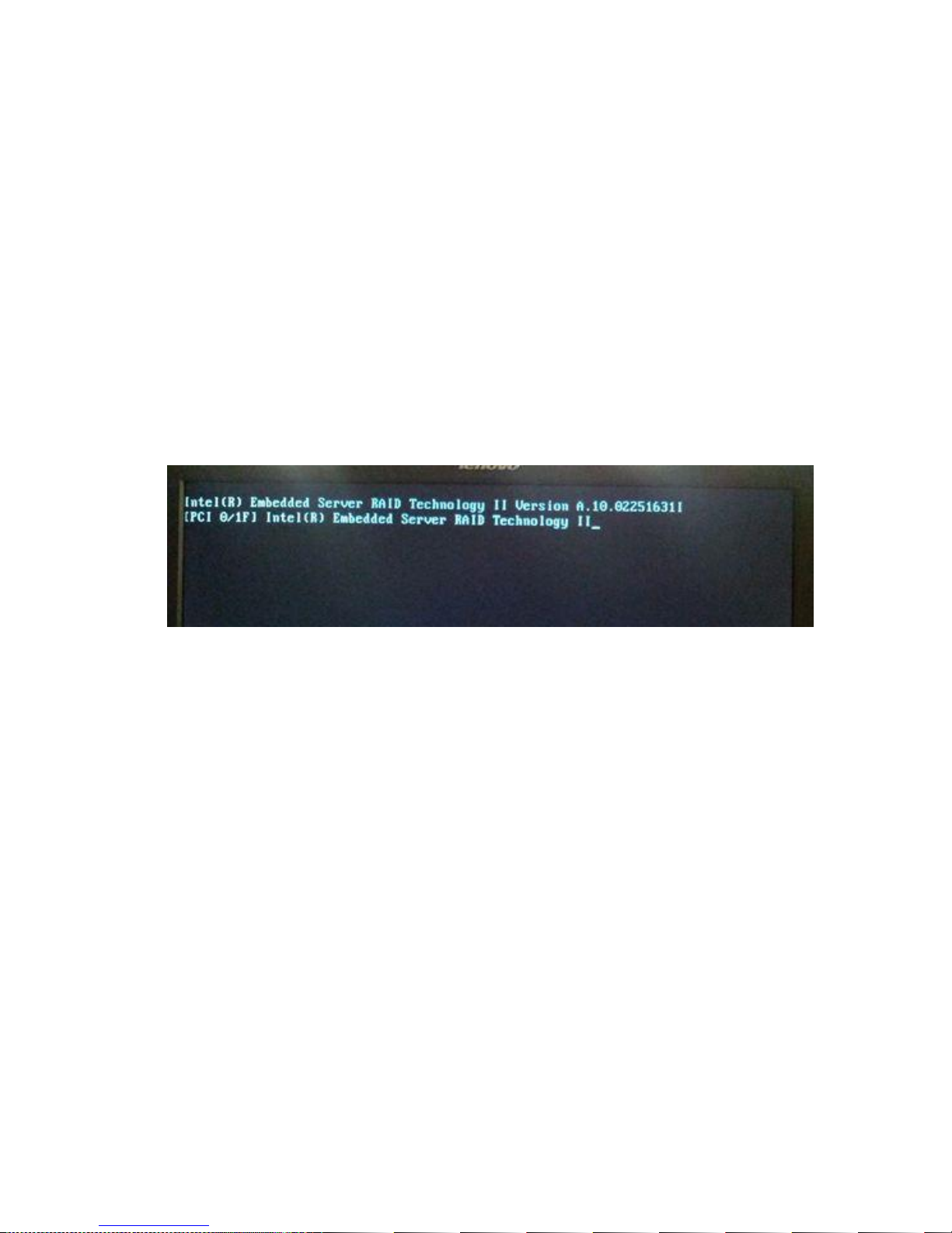
2. During normal startup, the server displays a number of boot up screens. The screen remains
blank for about 15 - 20 seconds, after which the Embedded RAID Controller startup screen
appears. An example is shown in Figure 4-1: “Boot up screen with Embedded Server RAID
startup”.
Figure 4-1: Boot up screen with Embedded Server RAID startup
17
3. The screen above remains for about 20 seconds, and is then updated with the current state
RAID information.
4. For normal operation, RAID screens present at least 2 drives present in port 0 and 1. In the
example shown in Figure 4-2: “Embedded Server RAID with status display” both port 0 and 1
are populated with drives reporting is size as about 953 GB.
5. The Virtual drive is configured as Online. This is the normal state.
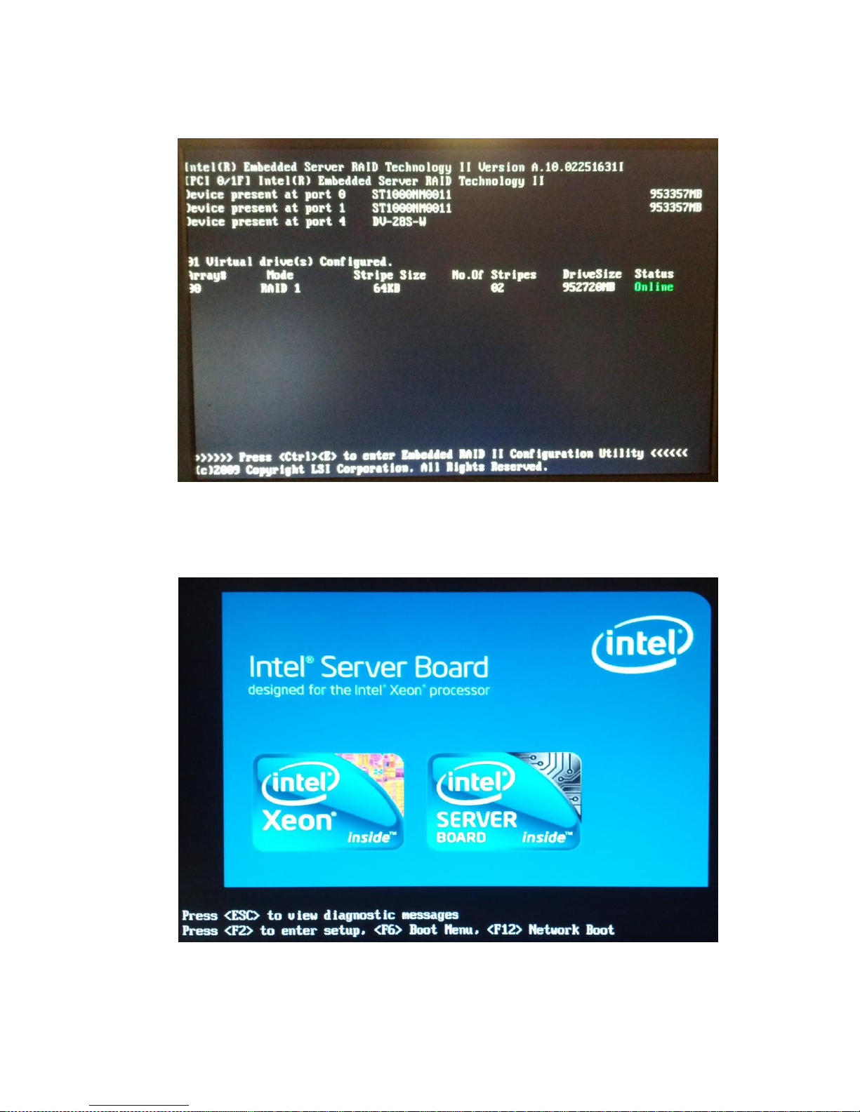
18 Connex Server Startup
Figure 4-2: Embedded Server RAID with status display
6. After approximately 7 seconds, the display updates to the Intel Server Board screen. An
example is shown in Figure 4-3: “System startup display with blue Intel logo”.
Figure 4-3: System startup display with blue Intel logo
7. Do not press any keys unless entering maintenance modes.
8. After a short pause, the display updates and the Windows Server 2008 operating system
begins to load. The animated Microsoft logo appears.
Note
If the Microsoft Initial Configuration Tasks window is displayed, click on the “X”
button to close.
9. Once the operating system startup is complete the administrator login screen appears.
10. At this point, the startup process is technically complete. However, it’s important to observe
some additional features as described in “Confirm Connex Server operational state”.
Confirm Connex Server operational state
1. Enter the Welch Allyn default user name and password for the server Administration account.
2. Upon success, the desktop screen is displayed.
On the desktop, double-click on . The Connex CS Admin Tools function launches.
a. If the icon is not present, go to Start > All Programs > Welch Allyn > Connex > Admin
Tools Launcher > (version number) to locate the program. Right-click on Welch Allyn
Admin Tools Launcher and select Send to > Desktop (create shortcut) to send a
shortcut to the desktop.
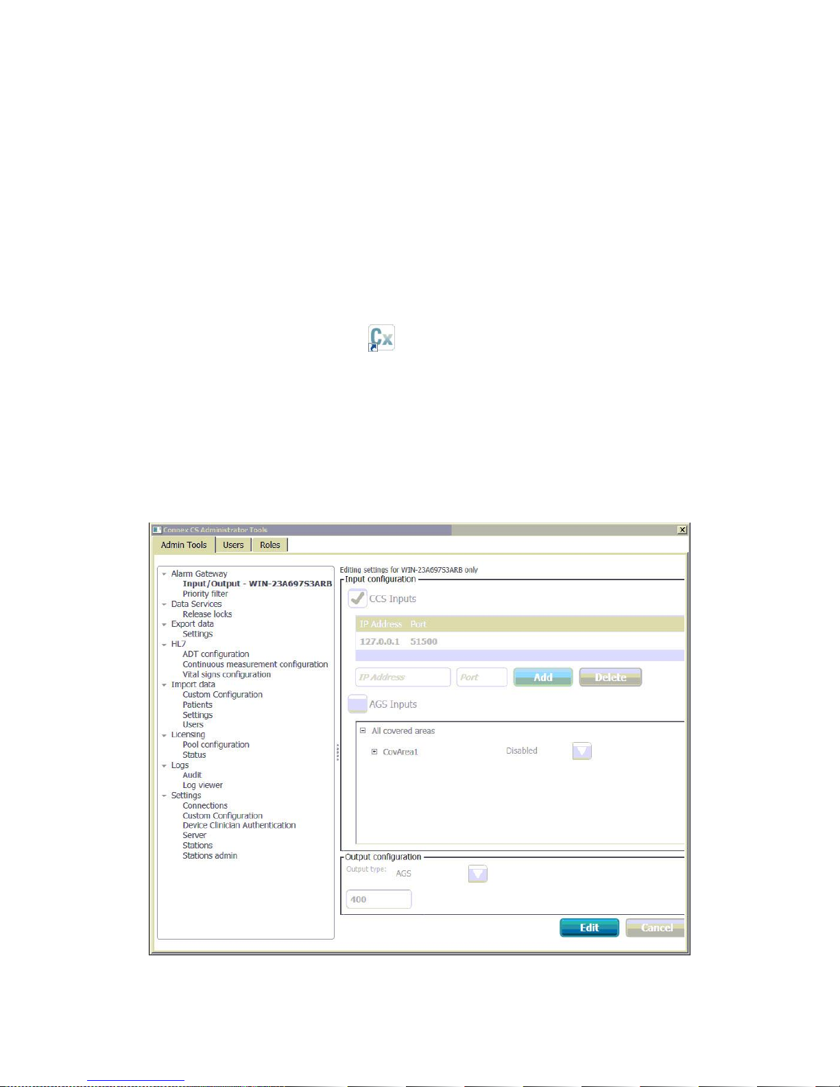
3. The Connex CS Administrator Tools window appears. This is similar to the Settings > Admin
tools tab window on the central station. An example is shown below in Figure 4-4:
“Administrator Tools startup window”.
19
Figure 4-4: Administrator Tools startup window
20 Connex Server Startup
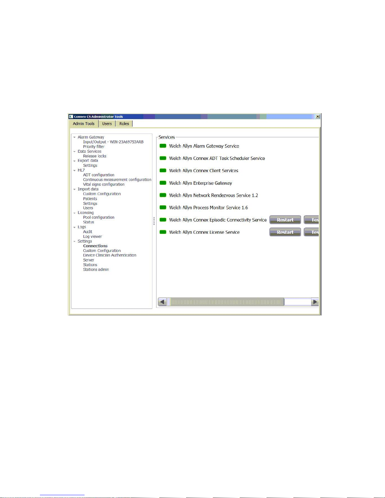
4. Click on Settings > Connections. The Services windows displays the state of all of the core
services running which make up the Connex Server application. An example is shown below
in Figure 4-5: “Administrator Tools setting connections window”.
5. A green state means that the service is currently running normally.
6. A red state means that the service is currently not running in a normal state or has stopped.
Figure 4-5: Administrator Tools setting connections window
To restart services:
Some services are dependent on others being started first.
1. If services need to be started, proceed by clicking on the Restart button in the following
sequence:
Client Services
License Service
Enterprise Gateway service
Episodic Connectivity Service
Alarm Gateway Service
ADT Task Scheduler Service
Network Rendezvous Service
Process Monitor Service.
2. The Services present in the working window depend on the features and licenses purchased.
Note
Some Services may not be present on previous versions of Connex CS.
Note
Before proceeding with this section, go to the Connex CS Central Station
Installation Guide to complete installation tasks for all central stations.
3. If one or more services cannot be restarted successfully, refer to Appendix A
“Troubleshooting” for additional information.
Confirm communication with central stations
This section assumes that all central stations have also been installed. Proceed with work to
complete Central Station installation before performing work in this section. Refer to the Connex
CS Central Station Install Guide as needed.
1. Ensure that all central stations have been installed and are reachable on the network.
2. On the Connex Server, open a command tool and ping each host by its assigned IP address.
Refer to the Connex CS Customer Project Req. Form, Section B information as needed.
3. On the server, open the Admin Tools again.
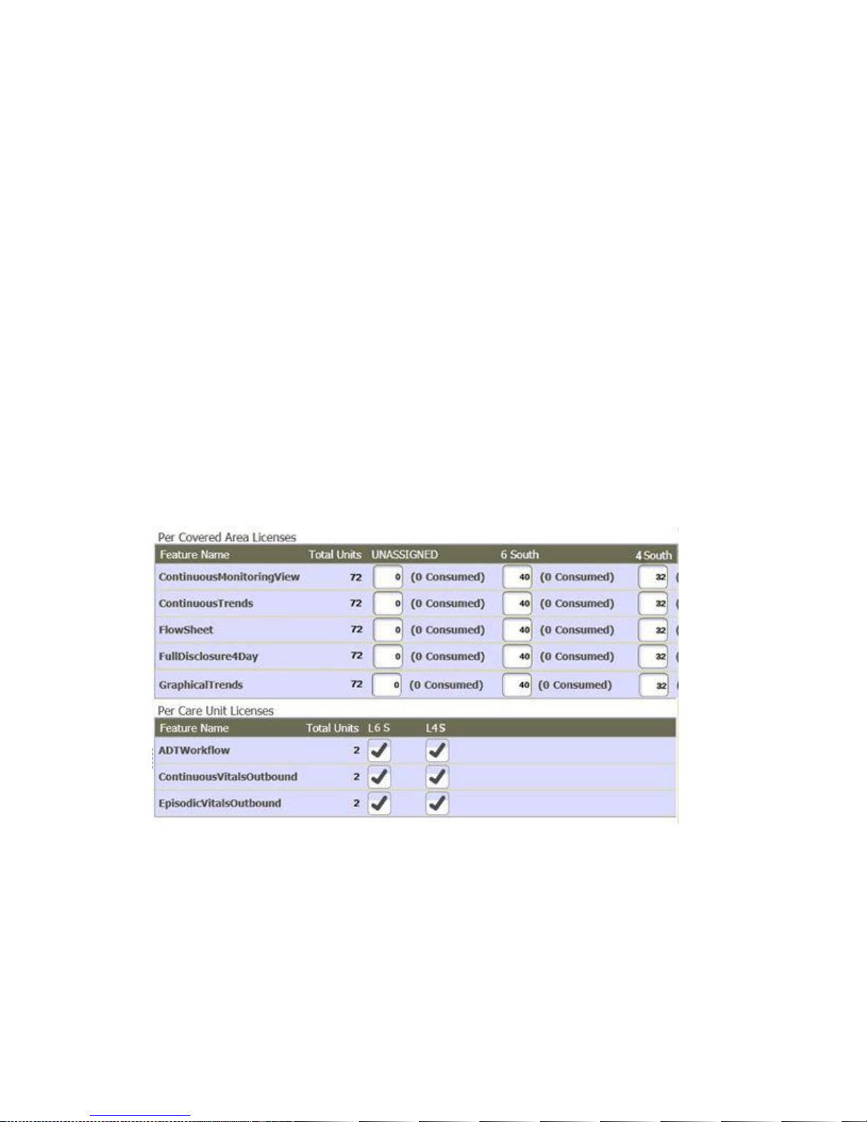
4. Navigate to Settings > License > Pool Configuration to view the Covered Area central
stations and their respective licensing allocations. An example is shown below in Figure 4-6:
“Administrator Tools license pool configuration window”.
21
Figure 4-6: Administrator Tools license pool configuration window
5. Confirm that all central stations installed on the network have a column present with the Covered
Area name displaying in the Per Covered Area Licenses window.
a. In the above example, there are two Covered Areas shown, 6 South and 4 South.
b. Licenses are allocated to both Covered Areas but with differing quantities.

Caution When making configuration changes for HL7, always refer to the
accompanying customer requirements documents, section D. Consult with the
Welch Allyn Project Manager and/or Applications Engineers as needed.
Caution Changes to a live network should always be done with care as system
outages may occur. Consult with the facility clinical and IT informatics
representatives in planning for changes.
Note
As the ADT connector port refers an internal port number used between the
Welch Allyn Enterprise Gateway Service (EGS) and Corepoint application, this
generally should never be changed.
22 HL7 Interface Configuration
5
There steps are only applicable for systems with HL7 messaging options, including ADT or ORU
interfaces.
HL7 Interface Configuration
Confirm Connex CS Admin tools configuration
1. On the desktop, double-click on . The Connex CS Admin Tools function launches.
a. If the icon is not present, go to Start > All Programs > Welch Allyn > Connex > Admin
Tools Launcher > (version number) to locate the program.
b. Right-click on Welch Allyn Admin Tools Launcher and select Send to > Desktop
(create shortcut) to send a shortcut to the desktop.
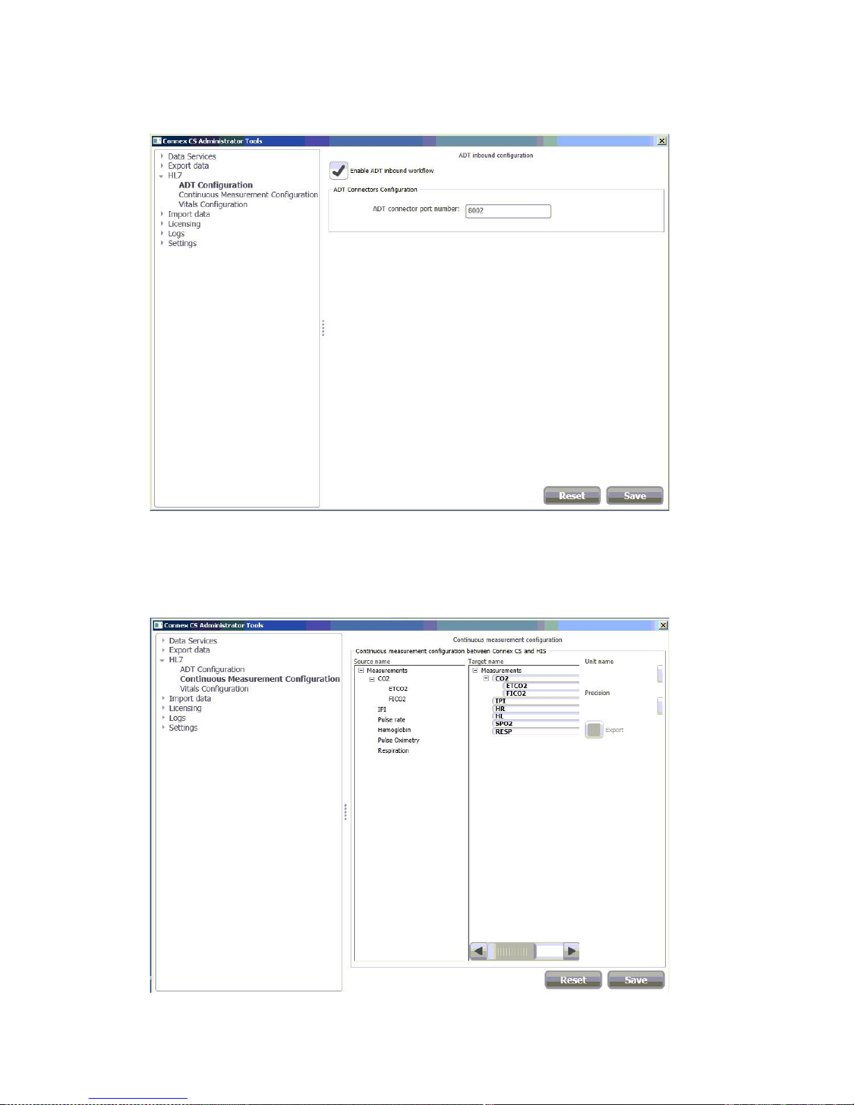
2. Click on Settings > HL7 > ADT Configuration. The ADT inbound configuration windows
appears. An example is shown in Figure 5-1: “Administrator Tools HL7 ADT configuration
window”.
3. Ensure that Enable ADT inbound workflow is checked. Do not change the ADT connector
port number unless specifically instructed by Welch Allyn Applications Engineering.
4. If changes are made, select Save when complete.
23
Figure 5-1: Administrator Tools HL7 ADT configuration window
5. If the site is configured to support continuous outbound ORU data, from the Admin Tools,
select HL7 > Continuous Measurement Configuration. See Figure 5-2: “Administrator
Tools HL7 continuous measurement configuration window” for an example.
Figure 5-2: Administrator Tools HL7 continuous measurement configuration window
Note
As the Episodic connector port refers an internal port number used between the
Welch Allyn Enterprise Gateway Service (EGS) and Corepoint application, this
generally should never be changed.
24 HL7 Interface Configuration
6. Refer to the Connex CS Customer Requirements Document, Appendix D1 and make
adjustments if needed.
7. If changes are made in this window, select Save when complete.
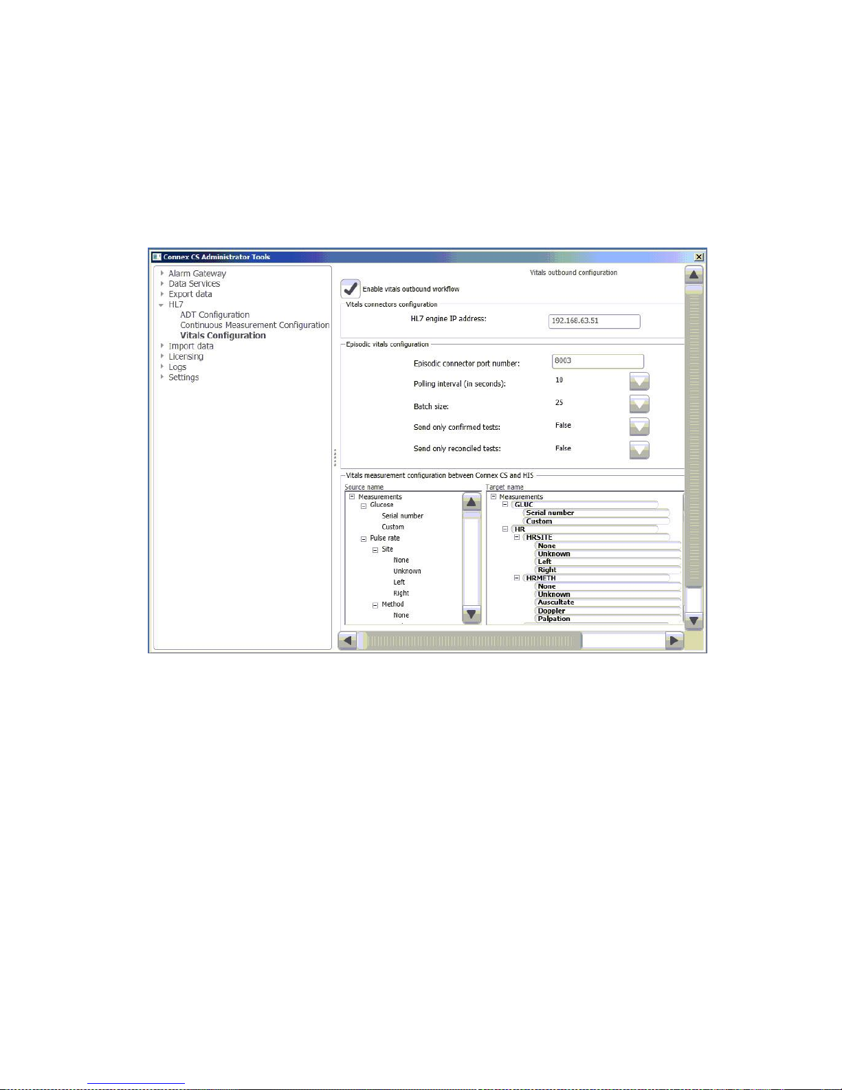
8. Select Vitals Configuration to configure episodic outbound ORU data. See Figure 5-3:
“Administrator Tools HL7 vitals configuration window” for an example.
Figure 5-3: Administrator Tools HL7 vitals configuration window
9. Ensure that Enable vitals outbound workflow is checked. If needed, change the Episodic
connector port number.
10. The HL7 engine IP address is the IP address of the Connex server’s interface which
communicates with the facilities HIS / EMR application. Refer to the Connex CS Customer
Project Req. Form, Section D document as needed for this information.
11. Configure additional settings and parameters for the Vitals outbound configuration as
needed, again referring to the document Connex CS Customer Project Req. Form,
Appendix D1 for the project.
12. If changes are made in this window, select Save when complete.
Importing a customer specific Corepoint NIX file
A majority of the configuration for Corepoint will be completed by a Welch Allyn Applications
Engineer. One of the major outputs of the process is an custom NIX file, which contains site
specific interface configuration rules and settings for a specific customer or site.
 Loading...