


 Loading...
Welch Allyn 88002, 88004, 88006, 89002, 89004 User manual
...Women's Health
Service Manual
Platform Colposcope
Video Colposcope
Models:
88002/88004/88006/89002/89004/89006
Colposcope vidéo
Video-Kolposkop
Video Colposcopio
Videocolposcopio
Operating Instruction
Manual
English . . . . . . . . . . . . . . .iii
Manuel d’utilisation
Français (French) . . . . . . .23
Bedienungsanleitung
Deutsch (German) . . . . . .49
Manuale di istruzioni sul funzionamento
Italiano (Italian) . . . . . . . . .75
Manual de instrucciones de operación
Español (Spanish) . . . . .101

Table of Contents
Conventions ................................................................................................ |
2 |
General Precautions................................................................................. |
2 |
Symbols................................................................................................... |
3 |
Summary of Warnings and Cautions....................................................... |
4 |
Components ................................................................................................ |
5 |
Video Colposcope ................................................................................... |
5 |
Optional Accessories............................................................................... |
5 |
Nomenclature ............................................................................................. |
7 |
Video Colposcope Front View ................................................................ |
7 |
Video Colposcope Side View .................................................................. |
7 |
Video Colposcope Back View................................................................. |
8 |
Video Colposcope Bottom View ............................................................. |
8 |
Vertical Pole Stand .................................................................................. |
9 |
Swing Arm Stand .................................................................................... |
9 |
Monitor.................................................................................................... |
10 |
Connection Diagrams ................................................................................ |
11 |
Connecting Video Colposcope with Monitor.......................................... |
11 |
Connecting Video Colposcope with VCR/Video Printer ........................ |
11 |
Preparation for Use.................................................................................... |
12 |
General Precautions................................................................................. |
12 |
Assembly of Video Colposcope .............................................................. |
12 |
Vertical Pole Stand Assembly ................................................................. |
12 |
iii
Swing Arm Stand Assembly ................................................................... |
13 |
Setting Up Video Colposcope ................................................................. |
14 |
Operation .................................................................................................... |
15 |
Power Switch........................................................................................... |
15 |
Lamp Ignition.......................................................................................... |
15 |
Focus and Zoom Controls ....................................................................... |
15 |
Green Filter Controls............................................................................... |
15 |
Illumination Beam Director .................................................................... |
15 |
Vertical Height Adjustment Ring ............................................................ |
15 |
Swing Arm Height Adjustment............................................................... |
15 |
Positioning Video Colposcope ................................................................ |
15 |
Remote Video Functions ......................................................................... |
15 |
Maintenance ............................................................................................... |
16 |
Video Colposcope Cleaning .................................................................... |
16 |
Disinfecting Solutions ............................................................................. |
16 |
Illumination Lens Cleaning..................................................................... |
16 |
Camera Lens Cleaning ............................................................................ |
16 |
Replacing Lamp ...................................................................................... |
17 |
Replacing Fuses....................................................................................... |
19 |
Service Information ................................................................................... |
19 |
Troubleshooting.......................................................................................... |
20 |
Specifications .............................................................................................. |
21 |
iv
Thank you for purchasing the Welch Allyn Video Colposcope. Follow the operation and maintenance instructions found in this manual and your video colposcope will provide you with many years of reliable service. Please read these instructions thoroughly before attempting to use your new video colposcope.
CAUTION: Federal law restricts sale of this device to, or to the order of, a physician or other appropriately licensed medical professional.
WARNING: Users of this equipment should be thoroughly trained in the appropriate medical procedures. Furthermore, they should take the time to read and understand these instructions before performing any procedure. They should also read and understand the instructions for any other equipment used in conjunction with the video colposcope (i.e. electrosurgical generators). Failure to do so may result
in injury to the patient and/or damage to the video colposcope.
IMPORTANT: The material outlined in this manual should be reviewed and understood prior to operation of the equipment.
NOTE: This equipment has been tested and complies with emissions standard EN60601-1-2: 1993, CISPR Publication 11:1990/EN55011: 1991 for Radiated and Conducted Emissions, Group 1, Class B.
This equipment also has been tested and complies with susceptibility standards to electrostatic discharge (ESD), radiated electromagnetic fields, fast transient bursts, and conducted surge interference. The procedures and criteria for conformance are contained in IEC801-2, 801-3, 801-4, 801-5, and EN60601-1-2: 1993.
In addition, this equipment has been tested and complies with EN6000-3-2 (1st Edition) covering harmonic disturbances in supply systems caused by household appliances and similar electrical equipment, Part 2, and EN 6000-3-3 (1st Edition) covering voltage fluctuation disturbances in supply systems caused by household appliances and similar electrical equipment Part 3.
INDICATIONS FOR USE: For examination of the tissues of the vagina, cervix, and external genitalia, to investigate, by means of magnification, abnormal cervical cytology or suspicious lesions of the lower female genital tract. Also used for corresponding biopsy and treatment, when indicated.
NOTE: This device complies with the guidelines of the American Conference of Governmental Industrial Hygienists threshold limits values for ultraviolet radiation for exposure time and distance consistent with the intended use of this device.
1
Conventions
WARNING: Warnings alert the user to the possibility of serious injury, death, or other adverse reaction associated with the use or misuse of the device.
CAUTION: Cautions indicate a potentially hazardous situation that, if not avoided, may result in minor or moderate injury and/or damage to the equipment. They also alert against unsafe practices.
NOTE: Notes provide supplemental information to the text and indicate a potentially hazardous situation, which, if not avoided, may result in property damage. They also highlight important information on the use of this equipment.
General Precautions
•For safety, the video colposcope should only be coupled to a grounded 110-120 VAC hospital-grade outlet (220 - 240 volt, 50 cycle international).
•The video colposcope should not be operated in the presence of flammable or explosive gases or chemicals, or installed in areas where these materials are commonly used.
•To avoid overheating, the video colposcope should not be positioned closer than 6” to any wall.
•Keep all liquids away from electrical equipment to avoid the possibility of shock and instrument damage.
•Occasionally inspect the power cord for signs of cuts, abrasions or dents.
•The video colposcope should never be stored or operated in areas where it could get wet or could be exposed to any environmental conditions like extreme temperature or humidity, direct sunlight, dust, etc.
•The lamp is extremely bright. DO NOT stare directly into illumination lens when the lamp is lit.
•All service to the video colposcope must be performed by Welch Allyn or by an authorized repair center.
•Video colposcope user should adhere to the operating conditions found in this manual. Otherwise, instrument damage may occur and/or operator/patient safety may be compromised.
•There are no user servicable parts (other than the lamp and fuses) in this unit or in its accessories. Any attempt to disassemble and/or repair this unit will result in voiding of the warranty.
2

Symbols
On: Power: Connects to the low voltage supply.
Off: Power: Disconnects from the low voltage supply.
Caution: Consult user's manual for additional information.
Warning: Consult user's manual for additional information.
Warning: High temperatures
Type B Equipment
Risk of fire. Replace fuses as marked.
Warning: High-intensity light
Warning: Power supply of unit is energized whenever power cord is plugged in.
The CE mark on this product indicates it has been tested to and conforms with the provisions noted in the 93/42/EEC Medical Device Directive.
Authorized European Representative:
European Regulatory Manager
Welch Allyn, Ltd.
Kells Road, Navan,
County Meath, Republic of Ireland
Tel 353 46 79060
Fax 353 46 27128
3

Summary of Warnings and Cautions
WARNING: All video monitors and peripheral equipment used with this instrument must be IEC 601-1 (or UL 2601) listed to comply with medical electrical safety guidelines. If not IEC 601-1(UL-2601) listed, the monitor/peripheral equipment should be positioned outside of the 6-foot patient contact area.
Please contact Welch Allyn for more information.
WARNING: Total system risk current should not exceed 50µA. An isolation transformer is required if the total system risk current exceeds 50µA when accessories are interconnected.
CAUTION: The video colposcope is cooled via a vent fan located in the back of the unit. The fan draws air from the front of and beneath the video colposcope and exhausts the air out the back of the video colposcope. Verify that the unit is no less than 6" from a wall.
WARNING: DO NOT use a converter adapter that will convert the three-prong AC plug to a two-prong line plug. The power supply in the video colposcope will not be properly grounded and electric shock might result.
CAUTION: DO NOT clean illumination lens with alcohol.
DO NOT touch optical or illumination lenses except as described in Maintenance section of this manual.
WARNING: The lamp operates at a high temperature. DO NOT attempt to remove the lamp before allowing it to cool. Allow at least five minutes for the lamp to cool before replacing. Replace with Welch Allyn lamp #09800 only.
CAUTION: The colposcope can be damaged if the unit is transported while holding the handle. The unit should be transported by grasping the pole.
4
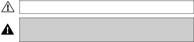
Components
Video Colposcope
88002 / 88004 / 88006
Video colposcope and vertical stand with vertical stand hardware kit:
•Allen wrench
•Allen bolt
•Mounting washer
•Spacer
89002 / 89004 / 89006
Video colposcope and swing arm stand with swing arm hardware kit:
•Allen wrench
•Bolt
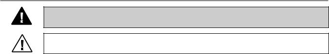
88600 |
S-Video Cable |
|
|
761076-0 |
Power Cord |
Optional Accessories
09800 |
Replacement Lamp |
|
|
88500 |
RS-232 Interface Cable |
5
|
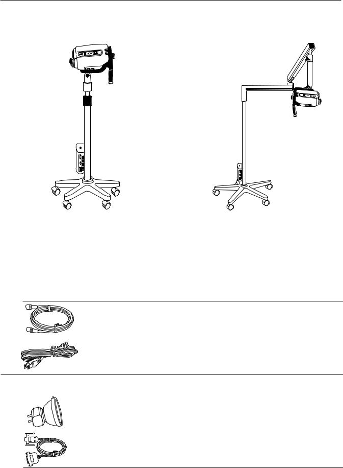
488307-9 |
Replacement Fuse |
|||||||
|
|
|
|||||||
|
88010 |
Cervical Model |
|||||||
|
|
|
|
|
|
|
|
|
|
|
|
|
|
|
|
|
|
|
|
|
|
|
|
|
|
|
|
|
|
|
|
|
|
|
|
|
|
|
|
|
|
|
|
|
|
|
|
|
|
88040 |
Dust Cover for Vertical Stand |
|
|
89040 |
Dust Cover for Swing Arm |
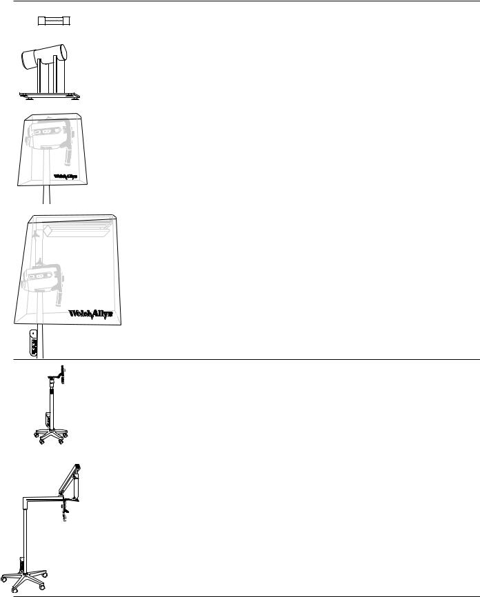
88030 |
Vertical Stand with Base Only |
|
|
|
|
|
|
|
|
|
|
89030 |
Swing Arm Stand with Base Only |
Note: Only accessories and components indicated in this manual are to be used with the Welch Allyn Video Colposcope system.
6
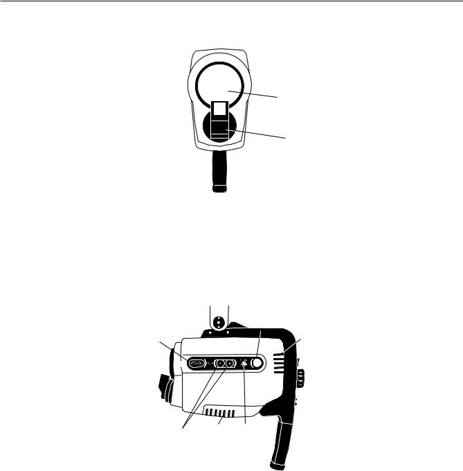
Nomenclature
Video Colposcope Front View
1
2
Name |
Function |
|
1. |
Objective lens |
The lens that establishes the magnification and field of view. |
2. |
Illumination beam director |
Directs lamp beam. |
Video Colposcope Side View
6
5 |
3 |
4 3 7
Name |
Function |
|
3. |
Ventilation slots |
Allow air to enter and leave unit, cooling internal components. |
4. Zoom control button |
Pressing + or - increases or decreases magnification accordingly. |
|
5. |
Focus control button |
Pressing < or > adjusts the focus. |
6. |
Green filter button |
Pressing turns the electronic green filter on or off. |
7. |
LED indicator |
Illuminates if the electronic green filter is on. Flashes during activation |
|
|
or deactivation. |
.
7
Video Colposcope Back View
8
9
11
12
10
Name |
Function |
|
8. |
Power switch |
Power control for the video colposcope. |
9. Ventilation slots |
Allow air to enter and leave unit, cooling internal components. |
|
10. |
Video colposcope handle |
For positioning the colposcope in the proper up/down, left/right |
|
|
position. |
11. |
Attachment knob |
Fastens handle to video colposcope. |
12. |
Remote video function buttons |
Allow use of remote video printer functions. |
Video Colposcope Bottom View
14
13
15
Name |
Function |
|
13. |
Lamp access door |
Removes for lamp replacement. |
|
|
(Note: If door is not properly closed, interlock power switches will not |
|
|
activate and the lamp will not start.) |
14. |
Ventilation slots |
Allow air to enter and leave unit, cooling internal components. |
15. |
Mounting piece |
Allows the video colposcope to attach to the stand. |
|
|
On the swing arm model, the mounting piece is located at the |
|
|
top of the colposcope. On the vertical stand model, the mounting |
|
|
piece is located at the bottom of the colposcope. |
8
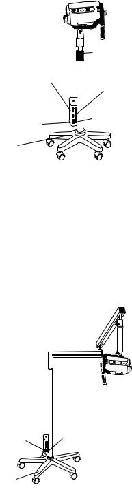
Vertical Pole Stand
21
|
|
20 |
19 |
|
|
|
|
|
|
17 |
18 |
|
|
|
|
|
|
16 |
|
Name |
Function |
|
|
16. |
Vertical rolling base stand |
Allows mobility with 5-caster base, including two locking casters. |
|
17. |
Fuse drawer |
Opens for replacement of fuses. |
|
18. |
Power supply cord receptacle |
Couples with power cord, which should be plugged into a 110-120 VAC |
|
|
|
hospital-grade outlet (220-240 volt, 50 cycle international). |
|
19. |
S-Video output |
Outputs Y/C (S-Video). |
|
20. |
RS232 interface cable output |
Couples with RS232 interface cable. |
|
21. |
Height adjustment ring |
Allows vertical movement and locking of stand at desired height; vertical |
|
|
|
height adjustment 36”-46” (91.4cm to 116.8cm). |
|
Swing Arm Stand
|
|
24 |
23 |
|
|
22 |
|
Name |
Function |
|
|
22. |
Swing arm rolling base stand |
Allows overhead positioning of the instrument with 5-caster weighted |
|
|
|
base, including two locking casters; vertical height 29.5” to 49.5” |
|
|
|
(74.9cm to 125.7cm). |
|
23. |
Power supply cord receptacle |
Couples with power cord, which should be plugged into a 110-120 VAC |
|
|
|
hospital-grade outlet (220-240 volt, 50 cycle international). |
|
24. |
Fuse drawer |
Opens for replacement of fuses. |
|
9
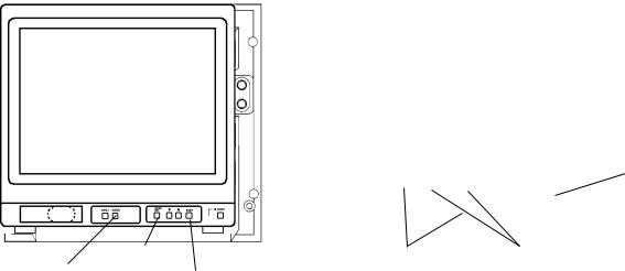
Monitor
NOTE: The following is a brief overview of the nomenclature of the Sony PVM-14N1U Video Monitor. For detailed instructions, please refer to the operation manual that is provided by the manufacturer.
Front Panel of Monitor |
Back Panel of Monitor |
|
|
|
|
|
|
|
|
31 |
|
27 |
|
|
|
|
|
25 |
|
|
|
|
|
|
|
|
||
|
|
|
|
|
|
|||
|
|
29 |
33 |
32 |
||||
|
26 |
28 30 |
|
|
|
|||
|
|
|
|
|
||||
PLEASE REFERENCE YOUR SONY MONITOR MANUAL FOR FURTHER INFORMATION. |
||||||||
Name |
|
|
|
Function |
|
|||
25. |
Power Switch |
|
|
|
Press to turn the monitor on. The indicator lights in green. To turn the |
|||
|
and Indicator |
|
|
|
power off, press again. |
|
||
26. |
Line A/Line B |
|
|
|
Press Line A if the signal is fed through a Line A connector on the back of |
|||
|
(input select) |
|
|
|
the monitor. Press Line B if the signal is fed through a Line B connector on |
|||
|
Buttons |
|
|
|
the back of the monitor. |
|
||
27. |
Menu/Exit |
|
|
|
Press to make the on-screen menu appear. Press again to leave the on- |
|||
|
|
|
|
|
screen menu. The following parameters can be modified using the on- |
|||
|
|
|
|
|
screen menu system: |
|
||
|
|
|
|
|
Volume - No function. |
|
||
|
|
|
|
|
Contrast - Adjust the contrast of the screen using the arrow buttons. |
|||
|
|
|
|
|
Brightness - Adjust the brightness of the screen using the arrow buttons. |
|||
|
|
|
|
|
Chroma - Adjust the color intensity of the video signal using the |
|||
|
|
|
|
|
arrow buttons. |
|
||
|
|
|
|
|
Phase - Adjust the phase of the video signals using the arrow buttons. |
|||
|
|
|
|
|
Color Select - Select the color system of the current input signals. |
|||
|
|
|
|
|
Language - Select the menu language. |
|
||
|
|
|
|
|
User memory - Select options for storing and recalling menu settings. |
|||
28. |
Down Arrow |
|
|
|
In item selection menus, moves the cursor downward. In adjustment and |
|||
|
|
|
|
|
setting menus, decreases the value of the selected item or moves |
|||
|
|
|
|
|
downward through item selections. |
|
||
29. |
Up Arrow |
|
|
|
In item selection menus, moves the cursor upward. In adjustment and |
|||
|
|
|
|
|
setting menus, increases the value of the selected item or moves |
|||
|
|
|
|
|
upward through item selections. |
|
||
30. |
Enter |
|
|
|
Chooses the selected item. Is active only during the first level of |
|||
|
|
|
|
|
on-screen selections. |
|
||
31. |
Power supply |
|
|
|
Couples with power cord, which should be plugged into a 110-120 VAC |
|||
|
|
|
|
|
hospital grade cord receptacle outlet (220-240 volt, 50 cycles |
|||
|
|
|
|
|
for international). |
|
||
32. |
Line A/Line B Video In |
|
|
|
Input connectors for composite video. |
|
||
33. |
Line A/Line B Y/C In |
|
|
|
Input connectors for high resolution S-Video |
|
||
NOTE: This monitor is shipped with default picture settings. Any change of the on-screen controls may result in poor picture quality.
10
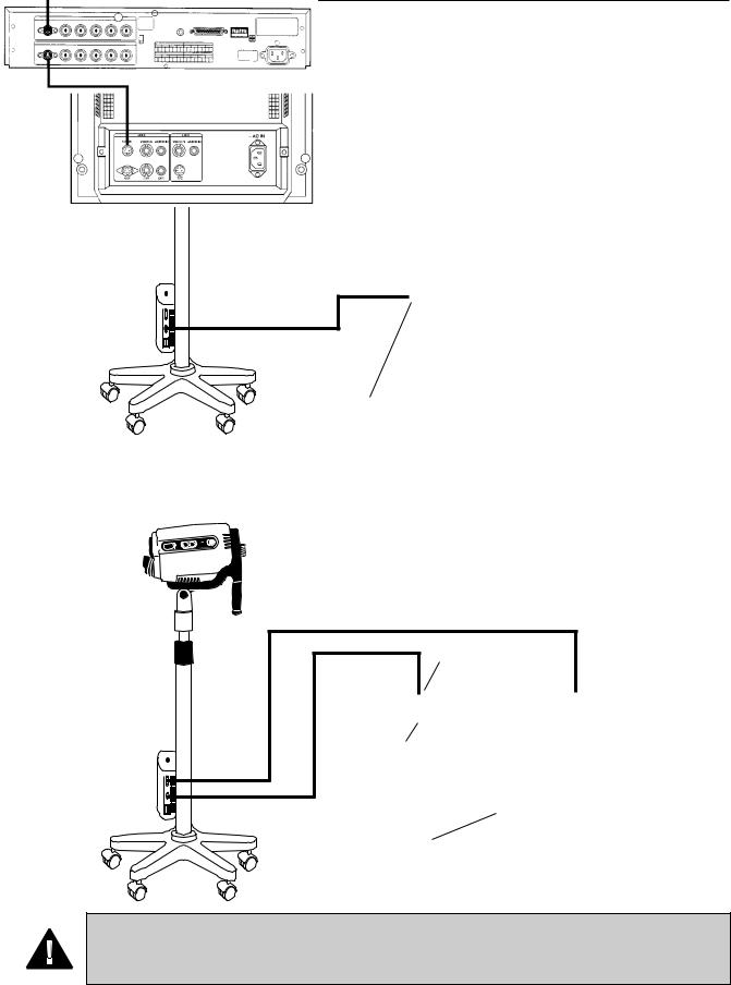
Connection Diagrams
Connecting Video Colposcope with Monitor
Back Panel of Monitor
S-Video Cable
Line A Y/C ln
Connecting Video Colposcope with VCR/Video Printer
RS232 Interface Cable
S-Video In
S-Video Out
S-Video Cable
Line A Y/C ln
Back Panel of Monitor
WARNING: All video monitors and peripheral equipment used with this instrument must be IEC 601-1 (or UL 2601) listed to comply with medical electrical safety guidelines. If not IEC 601-1(UL-2601) listed, the monitor/peripheral equipment should be positioned outside of the 6-foot patient contact area.
Please contact Welch Allyn for more information.
11

Preparation For Use
General Precautions
Make sure the unit is always grounded and secure during use. Do not disable power cord ground connection. Grounding reliability is achieved only when power cord is connected to a hospital-grade receptacle. Inspect the electrical plug and cord routinely. Do not use if damaged. Do not use the video colposcope in the presence of any flammable anesthetics.
Do not open the video colposcope housing. An electrical shock hazard exists due to high voltage. There are no user serviceable parts inside the video colposcope, except the lamp.
NOTE: Opening of the video colposcope housing by an unauthorized repair facility will void the product warranty.
WARNING: Total system risk current should not exceed 50µA. An isolation transformer is required if the total system risk current exceeds 50µA when accessories are interconnected.
CAUTION: The video colposcope is cooled via a vent fan located in the back of the unit. The fan draws air from beneath the video colposcope and exhausts the air out the back of the video colposcope.
Verify that the unit is no less than 6" from a wall.
WARNING: DO NOT use a converter adapter that will convert the three-prong AC plug to a two-prong line plug. The power supply in the video colposcope will not be properly grounded and electric shock might result.
CAUTION: The colposcope can be damaged if the unit is transported while holding the handle. The unit shjould be transported by grasping the pole.
Assembly of Video Colposcope
Before initial set up of the video colposcope, check all components received against the parts list of components (see Components section of this manual) to verify a complete set. If parts are missing, please notify Welch Allyn. Review the Nomenclature, Preparation for Use, Operation, and Maintenance sections to become familiar with the equipment.
Vertical Pole Stand Assembly
The video colposcope stand is shipped unassembled. Minimal assembly is required.
1.To assemble the stand, remove the stand and base parts from their cartons.
2.Place base upside down on the floor and insert casters into holes on the bottom of the base. (Do not place two locking casters next to each other.)
Locking caster
Locking caster
3. Place the base on the floor with casters down. Lock the two locking casters.
12
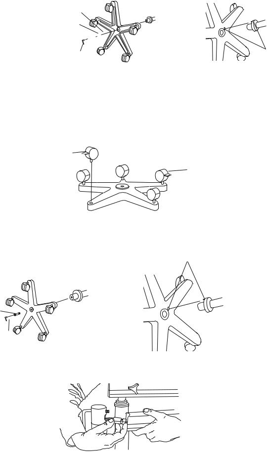
4.Place pole into the base, aligning the pin on the flange with the pin hole in the base. Place bolt, spacer, and washer, oriented as shown, into the pole. Tighten securely with the enclosed Allen wrench. (The assembly may need to be tilted.)
Washer
Spacer
Hex Bolt 

Allen Wrench |
Align pin |
|
with hole |
||
|
5. Before using the video colposcope, refer to “Setting Up Video Colposcope” section of this manual.
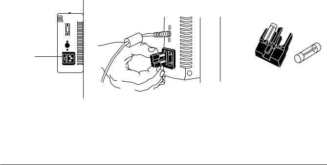
Swing Arm Stand Assembly
The video colposcope stand is shipped unassembled. Minimal assembly is required.
NOTE: BASE WEIGHS 58 LBS. YOU MAY REQUIRE ASSISTANCE TO LIFT IT.
1.To assemble the stand, remove the stand and base parts from the cartons.
2.Place base upside down on the floor and insert casters into holes on the bottom of the base. (Do not place two locking casters next to each other.)
Locking caster
Locking caster
3.Place the base on the floor with casters down. Lock the two locking casters.
4.Place the vertical pole section of the assembly into the base, aligning the pin on the flange with the pin hole in the base.
5. Locate the packaged bolt. |
Align pin with hole |
6.Place the bolt through the bottom of the pole. (The assembly may need to be tilted.)
Hex Bolt
Allen Wrench
7.Tighten securely with the enclosed Allen wrench.
8.Remove the bolt from the arm of the colposcope assembly and insert it through the hole near the top of the pole.
9.Position the pole and the arm of the remaining colposcope assembly in close proximity.
10. Connect the two wire harnesses via their connectors. (This may require assistance for proper assembly.)
13

11. Bring the colposcope swing arm assembly to the pole while at the same time pushing the electrical connectors into the colposcope arm.
12. Tighten the bolt securely with the enclosed Allen wrench. Be sure not to pinch any of the electrical wires between the vertical pole and arm of the colposcope assembly .
13. Before using the video colposcope, refer to Setting Up Video Colposcope section of this manual.
Setting Up Video Colposcope
1.Connect the power cord to the power cord receptacle in the power supply located on the video colposcope stand.
2.Plug the other end of the power cord into a properly grounded 110-120 volt AC outlet (220-240 volt, 50 cycle for international).
3.Connect the S-Video cable to the S-Video output on the side of the power supply located on the video colposcope stand.
4.Connect the other end of the S-Video cable into the Line C connector Y/C (S-Video) on the back of the monitor.
5.Plug the monitor into a properly grounded 110-120 volt AC outlet (220-240 volt, 50 cycle for international).
RS232 output
S Video output
14

Operation
Power Switch
With the power cord connected to a properly grounded outlet, and the S-video cable connected to the video colposcope and monitor, activate the power switch on the handle of the video colposcope.
Lamp Ignition
Once the video colposcope's power switch has been activated, the lamp will ignite. The lamp requires approximately 11 seconds to warm up.
Focus and Zoom Controls
Once the power switch has been activated, the video colposcope will execute a setup procedure, ending in the low magnification setting, or 4.5x. To obtain coarse focus, position the distal end of the video colposcope approximately 300mm from the target. Adjust the video colposcope by moving the stand (for vertical stand), or the arm (for the swing arm stand), until the picture is in focus. Press the + on one of the zoom controls until maximum magnification is obtained, and readjust the position of the stand or the swing arm until the picture is in focus. Fine focus, in either direction, is provided by the focus controls once coarse focus has been achieved. After coarse focus is achieved at maximum magnification, zoom control can be set to a desired lower magnification by pressing either zoom control. Focus will be maintained throughout the entire magnification range once these steps have been completed if the video colposcope or target is not moved.
Note: The setup (nominal) setting of the focus controls can be recovered by pressing one of the zoom + controls for 4 seconds after maximum magnification has been achieved.
Green Filter Controls
Activate the electronic green filter by pressing the green button located on either side of the video colposcope. Full activation of the green filter occurs in less than 10 seconds. Deactivated the filter by pressing the green filter button again. The green filter LED indicator flashes during activation and deactivation and remains on after activation is complete.
Illumination Beam Director
The illumination beam director can be rotated up to 45° clockwise or counterclockwise to better illuminate the examination area. To rotate the director, grasp the flat sides and twist in either direction as desired. The illumination beam director moves with some resistance. This helps to hold it securely in the desired position. The center position can be recovered by returning the director to the detent position.
Vertical Height Adjustment Ring (Vertical Colposcope Model Only)
The height of the vertical stand can be adjusted by rotating the black height adjustment ring, located on the pole of the stand, counterclockwise. Once the ring has been loosened, adjust the pole to the desired height and then tighten the ring again by rotating it clockwise.
Swing Arm Height Adjustment (Swing Arm Colposcope Model Only)
Adjust the height of the swing arm stand by loosening the height adjustment knob located on the arm of the stand. The swing arm can then be moved to the desired position. After moving the arm, tighten knob securely by rotating clockwise. The desired drag can be obtained by adjusting this knob either clockwise or counterclockwise.
Positioning Video Colposcope
The video colposcope can be angled up and down and left and right. To change the up/down tilt angle, loosen the knob located on the tilt axis. The video colposcope can then be tilted as necessary. To change the horizontal angle, loosen the knob located on the support shaft. The drag of either knob can be set by loosening or tightening as necessary.
Remote Video Functions
The handle of the video colposcope contains three buttons that control three video functions. These functions, provided by a remote video printer, are Freeze, Print, and Toggle. (See Connection Diagram section of this manual for connecting the printer to the video colposcope.)
1.Pressing the freeze (“F”) button stores a new image in printer memory. The frozen image is displayed on the monitor.
2.Pressing the copy (“C”) button prints the image displayed on the monitor. If live video is displayed, the image visible when the button was pressed will be printed.
3.Pressing the video (“V”) button changes the display from printer memory (frozen image) to live video, or from live video to printer memory (frozen image), depending on the current mode.
15

Maintenance
Video Colposcope Cleaning
Turn the power switch off and unplug the power cord from the electrical outlet prior to cleaning.
The video colposcope housing can be wiped down with a cloth dampened slightly with a mild solution of disinfectant. Be careful not to allow the plug prongs to get wet. Also be careful not to allow the camera lens or lamp lens to get wet.
Disinfecting Solutions
The disinfecting solutions listed below are safe for cleaning the housing of the video colposcope if used according to the manufacturer’s instructions for cleaning and disinfecting, and in accordance with procedures detailed in the cleaning section of this manual.
•Cidex, Cidex Plus
•70% isopropyl alcohol
•10% mild bleach solution
•Metricide
•10% Wescodyne
•Banicide
•Wavecide-01
Note: References to brand names are not endorsements of their efficacy as disinfecting solutions. However, tests have shown these solutions to be compatible with Welch Allyn colposcopes, providing the manufacturers' directions are followed. Do not use any other solutions unless a sample has been sent to Welch Allyn for compatibility testing.
IMPORTANT
Be careful not to allow solution to drip into the air vents.
DO NOT spray solution into the air vents.
DO NOT sterilize any part of the unit.
DO NOT IMMERSE any part of the unit in cleaning solutions.
Illumination Lens Cleaning
The lamp lens may be cleaned with a cloth dampened slightly with warm water and mild detergent.
CAUTION: DO NOT clean illumination lens with alcohol. DO NOT touch optical or illumination lenses except as described in Maintenance section of this manual.
Camera Lens Cleaning
The camera lens may be cleaned with isopropyl alcohol or any commercial lens cleaner.
16

Replacing Lamp
WARNING: The lamp operates at a high temperature. DO NOT attempt to remove the lamp before allowing it to cool. Allow at least five minutes for the lamp to cool before replacing. Replace with Welch Allyn lamp #09800 only.
1.Turn the power switch off and unplug the power cord from the electrical outlet.
2.Holding the video colposcope as shown, turn the knob located at the back of the handle counterclockwise and unscrew and remove the video colposcope from the handle.
3.Place the unit on a suitable work surface. Slide the lamp access door away from the housing as shown until the door is completely removed.
4. Unplug the lamp from the electrical connector.
17
5. Push the retainer spring toward the back of the colposcope and remove the lamp from its housing.
6.Remove a Welch Allyn replacement lamp # 09800 from its package. Do not touch the lamp itself or the interior reflective surface of the lamp. Skin oils will cause premature lamp failure. Hold lamp by the outside of the reflector or the connector only. Remove any grease or fingerprints with a clean cotton swab moistened with alcohol. Do not leave any lint on the lamp.
7.Holding the retainer spring as in step 5, slide the new lamp into the lamp housing so that the lamp's alignment pin engages the alignment slot in the lamp holder. (Make sure lamp is properly seated and snaps into place.)
8.Plug the electrical connector onto the new lamp.
9.Slide the lamp access door securely back into place, reversing the process described in step 3 above.
10.Place the video colposcope back into the handle, making sure the power connector is engaged.
11.Tighten the knob by rotating clockwise until snug.
12.Plug the power cord back into the electrical outlet.
18
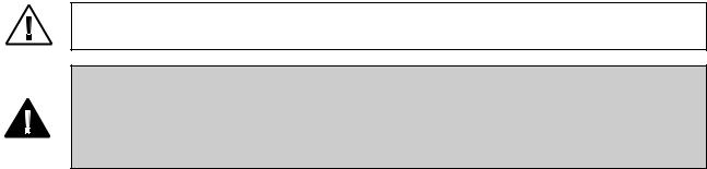
Replacing Fuses
Two fuses are located in slots adjacent to the power supply cord receptacle on the side of the power supply housing. This housing is attached to the pole of the video colposcope stand.
1.To replace a blown fuse, remove the fuse holder by pressing the tab and pulling the holder out of the power supply
2.Pull out and remove the blown fuse from the fuse holder.
Tab
3.Replace with new fuses # T1.00L-250V 1A Time Lag/Low Breaking Capacity (Welch Allyn Part # 488307-9).
4.Reinsert the fuse holder by pressing until it snaps into place.
Service Information
Customers in North America should return instruments requiring service to the Welch Allyn Technical Service Department listed below, or to an authorized Welch Allyn distributor.
Technical Service Department
Welch Allyn, Inc.
4341 State Street Road
Skaneateles Falls, NY 13153-0220
U.S.A.
Telephone: 1-800-535-6663
Fax: 315-685-4653
Customers outside of North America should return their units to a local, authorized Welch Allyn distributor, or to their nearest Welch Allyn service center.
Welch Allyn, Inc., U.S.A. - 4341 State Street Road, Skaneateles Falls, NY 13153-0220, Tel: 800-535-6663, Fax: 315-685-4653 Welch Allyn, Ltd., Canada - 160 Matheson Blvd. E., Unit #3, Mississauga, Canada L4Z 1V4, Tel: 905-890-0004, Fax: 905-890-0008 Welch Allyn, Ltd., UK - Aston Abbots, Buckinghamshire, England HP22 4ND, Tel: 011-44-1296-682140, Fax: 011-44-1296-682104
Welch Allyn, GmbH, Germany - Zollerstrasse 2-4, D72417 Jungingen, Germany, Tel: 011-49-7477-9271-73, Fax: 011-49-7477-9271-93 Welch Allyn, Ltd., Singapore - 6001 Beach Road #21-09, Golden Mile Tower, Singapore 199589, Tel: 011-65-291-0882,
Fax: 011-65-291-5780
Welch Allyn, Ltd., Australia - PO Box 864, Ground Floor, 18-20 Orion Road, Lane Cove, NSW 2066, Australia, Tel: 011-61-294-183-155, Fax: 011-61-294-183-650
The part and serial numbers are located on the housing of the colposcope near the fan. Remove the colposcope from the handle to locate these numbers.
19

Troubleshooting
Condition |
Check |
Action |
Power does not come on. |
Power cord |
Check connections at power supply and wall outlet. |
|
Attachment of unit to handle |
Check colposcope unit's alignment with handle. |
|
|
|
No image on monitor. |
Attachment of unit to handle |
Make sure lamp access door and handle are properly |
|
and door to unit |
attached. |
|
Fuses |
Remove fuse panel & replace blown fuse with T1.00L |
|
|
250V 1A time lag (Welch Allyn part # 488307-9). |
|
Wall outlet |
Plug the power cord into a wall outlet known to work. |
|
Monitor/other peripheral |
Make sure power is on for all devices. |
|
devices |
|
|
Cable connections |
Make sure all video cables are connected properly. |
|
Monitor input selection |
Make sure correct input selection is made on the front |
|
|
panel. |
|
|
|
Lamp will not light. |
Lamp housing |
Make sure lamp assembly is installed properly. |
|
Lamp |
Replace lamp. |
|
Lamp access door |
Make sure lamp access door is properly closed. |
|
|
|
Printer does not respond |
Power cord and printer |
Unplug power cord from wall outlet, then plug cord |
properly to handle |
|
back in to outlet. At the same time, turn printer off and |
buttons. |
|
then on again. |
|
Printer |
Make sure printer is on and is properly connected. |
|
|
|
20

Specifications
Item |
Specification |
Technical Data |
|
Power requirements |
Voltage |
115 VAC domestic |
|
|
|
220 -240 VAC international |
|
|
Frequency |
50/60 Hz |
|
|
Current |
1.0 Amp |
|
|
|
|
|
Dimensions |
Vertical stand |
Low: 36.0”, high: 46.0” |
|
|
|
(91.4 cm” to 116.8cm) |
|
|
Swing arm stand |
Low: 29.5”, high: 49.5” |
|
|
|
(74.9cm to 125.7cm) |
|
|
Optical centerline to swing arm |
15.0” (38.1 cm) |
|
|
bottom |
|
|
|
Colposcope HxWxD (excluding |
8.25” x 5.75” x 3.37” (21.0cm x |
|
|
handles) |
14.6cm x 8.6cm) |
|
|
|
|
|
Weight |
Colposcope |
3.1 lbs (1.4 kg) |
|
|
Vertical stand |
25 lbs (11.3 kg) |
|
|
Swing arm stand |
80 lbs (36.3 kg) |
|
|
|
|
|
Focal length |
300mm |
|
|
|
|
|
|
Magnification |
4.5x - 25x (typ.) |
|
|
|
|
|
|
Field of view |
66mm - 14mm |
|
|
|
|
|
|
Depth of field |
112mm - 5mm |
|
|
|
|
|
|
Operating environment |
Ambient temperature |
50° F (+10° C) to 104° F (+40° C ) |
|
Relative humidity |
95% |
||
|
|||
|
Atmospheric pressure |
70kPa to 110kPa |
|
|
|
|
|
Illumination |
Lamp type |
21 Watt metal halide arc |
|
Lamp life |
750 hrs @ 1 hr per start |
||
|
|||
|
Brightness adjustment |
Automatic electronic shutter |
|
|
Lamp |
Welch Allyn part no. 09800 |
|
|
Lamp voltage |
60 Volts |
|
|
|
|
21

Item |
Specification |
Technical Data |
|
|
|
|
|
Cooling method |
Forced air via fan |
|
|
|
|
|
|
Color system |
Color mosaic CCD |
|
|
|
|
|
|
Video output |
Y/C (S-Video) |
|
|
|
|
|
|
Transport/Storage environment |
Ambient temperature |
-40° F (-40° C) to 122° F (+50° C) |
|
|
Relative humidity |
95% max. |
|
|
|
|
|
Output devices |
VCR |
|
|
|
Monitor |
|
|
|
Thermal or video printer |
|
|
|
|
|
|
Compliance |
Listed |
UL2601-1 |
|
|
Listed |
CAN/CSA C22.2 No.601.1 |
|
|
Listed |
IEC601-1 |
|
|
Certified |
IEC601-1-2 |
|
|
Conformance |
CE |
|
|
Explosion proofing |
Use with potentially flammable |
|
|
|
surroundings is prohibited. |
|
|
|
|
|
Fuses |
T1.00L-250V |
1 Amp time lag, |
|
(Welch Allyn part # 488307-9) |
low breaking capacity |
||
|
|||
|
|
|
|
Classification |
Electro medical equipment |
Class I equipment |
|
|
Degree of protection |
Type B |
|
|
against electrical shock |
|
|
|
|
|
|
Patents |
This product is covered by the following patents: |
||
|
5,083,059; 5,117,154; 5,138,228; 5,144,201; 5,291,100; D391,360. |
||
|
Patents pending. |
|
|
|
|
|
|
The CE mark on this product indicates it has been tested to and conforms with the provisions noted in the 93/42/EEC Medical Device Directive.
Authorized European Representative:
European Regulatory Manager
Welch Allyn, Ltd.
Kells Road, Navan,
County Meath, Republic of Ireland
Tel 353 46 79060
Fax 353 46 27128
22

Table des matières
Conventions .......................................................................................... |
26 |
Précautions générales ...................................................................... |
26 |
Symboles ......................................................................................... |
27 |
Récapitulatif des avertissements et précautions .............................. |
28 |
Composants .......................................................................................... |
29 |
Colposcope vidéo ............................................................................ |
29 |
Accessoires en option ...................................................................... |
29 |
Nomenclature ....................................................................................... |
31 |
Colposcope vidéo — vue de face .................................................... |
31 |
Colposcope vidéo — vue latérale ................................................... |
31 |
Colposcope vidéo — vue arrière ..................................................... |
32 |
Colposcope vidéo — vue du fond ................................................... |
32 |
Socle à potence verticale ................................................................. |
33 |
Socle à bras pivotant ....................................................................... |
33 |
Moniteur .......................................................................................... |
34 |
Schémas de connexion ........................................................................ |
35 |
Connexion du colposcope vidéo au moniteur ................................. |
35 |
Connexion du colposcope vidéo au magnétoscope/ |
|
à l’imprimante ................................................................................. |
35 |
Préparation à l’emploi ......................................................................... |
36 |
Précautions générales ...................................................................... |
36 |
Montage du colposcope vidéo ......................................................... |
36 |
Montage du socle à potence verticale ............................................. |
36 |
23
Montage du socle à bras pivotant ................................................... |
37 |
Réglage du colposcope vidéo ......................................................... |
38 |
Fonctionnement .................................................................................... |
39 |
Commutateur de mise sous tension ................................................ |
39 |
Allumage de la lampe ..................................................................... |
39 |
Contrôles de focalisation et du zoom ............................................. |
39 |
Contrôles du filtre vert .................................................................... |
39 |
Directeur du faisceau d’illumination ............................................... |
39 |
Bague de réglage de la hauteur verticale ........................................ |
39 |
Réglage de la hauteur du bras pivotant ........................................... |
40 |
Positionnement du colposcope vidéo ............................................. |
40 |
Fonctions vidéo à distance .............................................................. |
40 |
Entretien ................................................................................................ |
41 |
Nettoyage du colposcope vidéo ...................................................... |
41 |
Solutions désinfectantes ................................................................. |
41 |
Nettoyage de la lentille d’illumination ........................................... |
41 |
Nettoyage de la lentille de la caméra .............................................. |
41 |
Remplacement de la lampe ............................................................. |
42 |
Remplacement des fusibles ............................................................ |
44 |
Informations concernant le service ..................................................... |
45 |
Dépannage ............................................................................................. |
46 |
Caractéristiques .................................................................................... |
47 |
24
Nous vous remercions d’avoir fait l’acquisition du colposcope vidéo Welch Allyn. Suivez les directives de fonctionnement et d’entretien contenues dans ce manuel pour assurer le fonctionnement précis et fiable de l’instrument pendant de nombreuses années. Veuillez lire intégralement ces instructions avant d’utiliser votre nouveau colposcope vidéo.
PRECAUTION: La loi fédérale des États-Unis limite la vente de cet instrument à un médecin ou à un autre professionnel de la santé agréé ou à leur ordre.
AVERTISSEMENT : Les utilisateurs de cet équipement doivent être totalement formés aux procédures médicales appropriées. Ils devront en outre prendre le temps de lire et d’assimiler ces instructions avant d’effectuer toute procédure. Ils devront aussi lire et assimiler les instructions concernant tout autre équipement utilisé en conjonction avec le colposcope vidéo (par ex. des générateurs électrochirurgicaux). Le non-respect de ces instructions peut provoquer des blessures aux patientes et/ou des dommages au colposcope vidéo.
IMPORTANT : Avant de faire fonctionner l’équipement, lire et assimiler les informations contenues dans ce manuel.
REMARQUE : Les résultats des tests auxquels a été soumis cet équipement sont conformes aux dispositions de la norme EN60601-1-2: 1993 concernant les émissions, et de la Publication CISPR 11:1990/EN55011:1991 concernant les émissions par rayonnement et les émissions par conduction, groupe 1, classe B.
Les résultats des tests auxquels a été soumis cet équipement sont également conformes aux dispositions des normes de susceptibilité aux décharges électrostatiques, aux champs électromagnétiques rayonnés, aux salves de surtensions rapides et aux brouillages de surtensions transmis par conduction. Les procédures et critères de conformité figurent dans les normes IEC801-2, 801-3, 801-4, 801-5 et EN60601-1-2: 1993.
En outre, les résultats des tests auxquels a été soumis cet équipement sont conformes aux dispositions de la norme EN6000- 3-2 (1ère édition) couvrant les distorsions harmoniques des systèmes d’alimentation provoquées par les appareils ménagers et équipements électriques similaires, partie 2, ainsi qu’à la norme EN6000-3-3 (1ère édition) couvrant les perturbations provoquées par les fluctuations de tensions des systèmes d’alimentation dues aux appareils ménagers et équipements électriques similaires, partie 3.
INDICATIONS D’EMPLOI : Examen des tissus du vagin, du cervix et des organes génitaux externes, afin de rechercher, par le biais du grossissement, une cytologie anormale du col utérin ou des lésions suspectes des voies génitales féminines inférieures. Utilisé également dans le cadre de biopsies et de traitements jugés nécessaires.
REMARQUE : Cet instrument est conforme aux valeurs limites des seuils de rayonnement ultraviolet, en termes de durée d’exposition et de distance correspondant à son emploi prévu, précisées dans les directives de l’American Conference of Governmental Industrial Hygienists.
25

Conventions
AVERTISSEMENT : Les avertissements signalent à l’utilisateur un risque de blessures graves, un danger de mort ou tout autre effet indésirable associé à l’emploi ou à l’abus de l’instrument.
PRÉCAUTION : Les précautions indiquent une situation potentiellement dangereuse qui, si elle n’est pas évitée, peut entraîner des blessures mineures ou modérées et/ou des dommages matériels. Elles signalent également des pratiques dangereuses.
REMARQUE : Les remarques fournissent des informations supplémentaires au texte et indiquent une situation potentiellement dangereuse qui, si elle n'est pas évitée, peut entraîner des dommages matériels. Elles soulignent également d'importantes informations concernant l'emploi de cet équipement.
Précautions générales
•Par mesure de sécurité, ne brancher le colposcope vidéo qu'à une prise 110-120 V c.a. (pays internationaux 220-240 V c.a., 50 cycles) de qualité hospitalière et mise à la terre.
•Ne pas utiliser le colposcope vidéo en présence de gaz ou de produits chimiques inflammables ou explosifs ; ne pas l'installer dans des lieux où ces matériaux sont couramment utilisés.
•Pour empêcher la surchauffe du colposcope vidéo, ne pas le placer à moins de 15,2 cm d'un mur.
•Éloigner les liquides de l'équipement électrique pour éviter le risque d'électrocution et de dommages à l'instrument.
•Examiner périodiquement le cordon d'alimentation pour s'assurer qu'il ne présente aucun signe de coupure, d'abrasion ou d'éraflure.
•Ne jamais ranger ou utiliser le colposcope vidéo dans des lieux où il risquerait de se mouiller ou d'être exposé à des conditions environnementales comme des températures ou une humidité extrêmes, la lumière solaire directe, la poussière, etc.
•La lampe est extrêmement brillante. NE PAS regarder directement la lentille d'illumination quand la lampe est allumée.
•Toutes réparations du colposcope vidéo doivent être confiées à Welch Allyn ou à un centre de réparation agréé.
•L'utilisateur du colposcope vidéo respectera les conditions de fonctionnement indiquées dans ce manuel. Sinon, des dommages à l'instrument peuvent en résulter et/ou la sécurité de la patiente/de l'opérateur risque d'être compromise.
•Il n'y a aucune réparation qui peut être effectuée par l'utilisateur (sauf le remplacement de la lampe et des fusibles) ni dans cette unité ni dans les accessoires. Si vous essayez d'ouvrir le boîtier ou de réparer l'unité, la garantie sera annulée.
26
Symboles
Sous tension : Alimentation : branchement à l'alimentation basse tension.
Hors tension : Alimentation : débranchement de l'alimentation basse tension.
Précaution : Consulter le manuel d'utilisation pour des informations supplémentaires.
Avertissement : Consulter le manuel d'utilisation pour des informations supplémentaires.
Avertissement : Hautes températures
Équipement de type B
Risque d'incendie. Remplacer les fusibles comme indiqué.
Avertissement : Lumière à haute intensité
Avertissement : L'unité est alimentée dès que le cordon d'alimentation est branché.
La marque CE figurant sur ce produit indique que les résultats des tests auxquels il a été soumis sont conformes aux dispositions enregistrées dans la Directive 93/42/CEE concernant les instruments médicaux.
Représentant européen agréé :
European Regulatory Manager
Welch Allyn, Ltd.,
Kells Road, Navan,
County Meath, Republic of Ireland
Tél. 353 46 79060
Télécopieur 353 46 27128
27
Loading...