

Welch Allyn 6102, 6154 Installation Instructions Manual
Welch Allyn, Inc.
Note
2
4
7
6
1
3
5
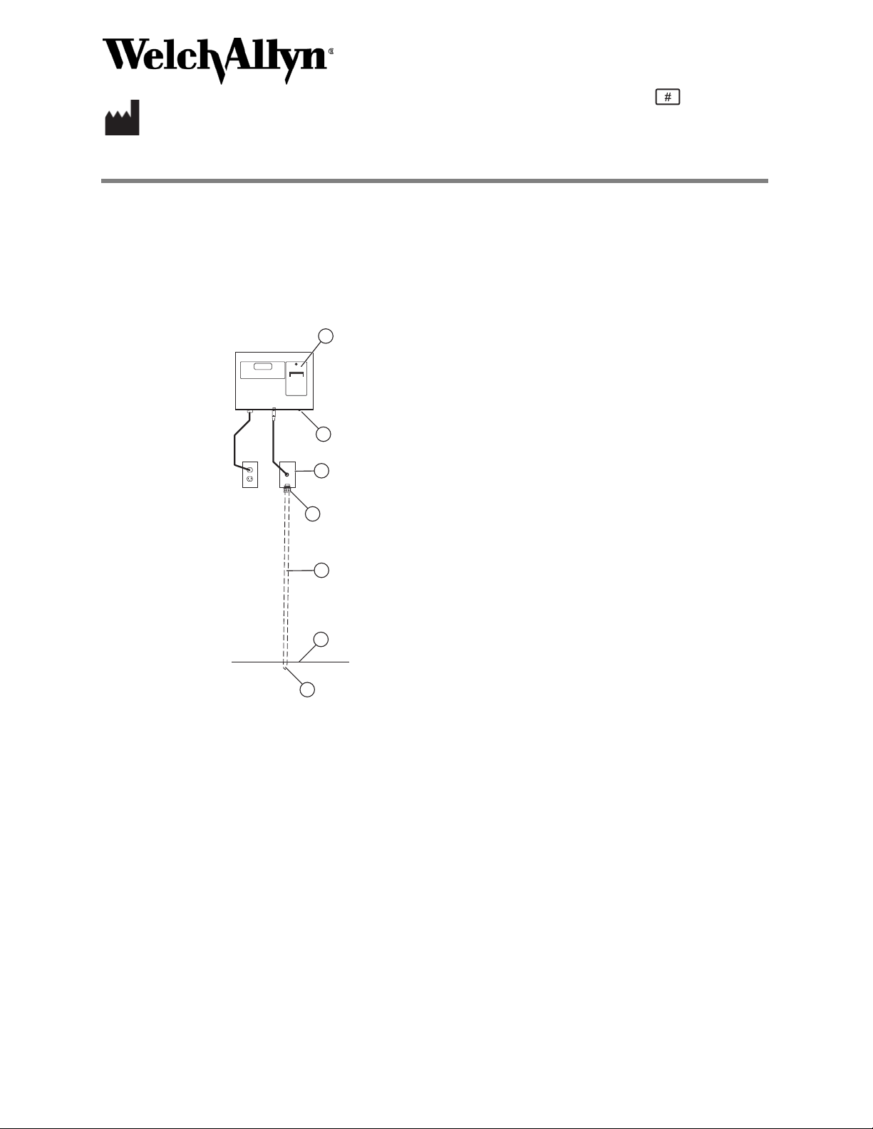
1. Printer (optional)
2. #10-32 screws for the mounting bracket
3. Cover plate for platform cable
4. Liquid-tight connector
5. Conduit for platform cable
6. Floor
7. Conduit end to scale
4341 State Street Road
Skaneateles Falls, NY 13153 USA
DIR 80021908 Ver. A
Revised 2016-12
Readout panel and scale installation instructions
The Welch Allyn In-Floor Scale models 6102 and 6154 are installed into the floor and display the
patient measurements on a readout either surface-mounted or flush-mounted on a wall.
If your scale has a flush-mounted readout, see “Flush-mounted readout panel installation” on
page 2.
Surface-mounted readout panel installation
726081
Use the following instructions to surface mount the readout panel:
1. Locate a stud in the wall nearest to the scale platform location. This location should be 6 to 8 in.
from the center of the side of the platform nearest the wall to allow the readout panel to be
centered.
2. Remove the two screws from the rear of the mounting bracket connected to the scale readout.
Save these screws for use later.
3. Mount one side of the bracket to a stud. If a stud is not used, make sure to use anchoring bolts
or other suitable hardware for added strength. Make sure the bracket is installed close to an AC
outlet to provide power to the readout panel.
4. Measure 48 inches up from the floor or to the desired height for the bottom of the readout
panel.
The buttons and LED display are approximately 7 inches above the bottom of the readout
enclosure.
5. Hold the mounting bracket against the wall with the two tabs facing up and mark the locations
of the four mounting holes. Use a level to ensure that the readout is installed at the proper
angle.
6. Use four bolts (not included) to fasten the bracket to the wall. The readout panel cabinet has
four 3/4-inch holes to allow for clearance of the mounting bolt heads.
For information about any Welch Allyn product, visit: http://www.welchallyn.com/en/other/contact-us.html.

2 80021908 Ver A Welch Allyn
Note
Note
7. Place the readout panel cabinet onto the mounting bracket. Make sure the both tabs slide into
the slots on the back of the cabinet.
It is not necessary to remove the front cover from the readout panel cabinet for installation.
8. Use the two screws removed in Step 2 to fasten the bottom of the readout panel cabinet to the
bracket.
9. Use the following procedure to install the platform cable conduit and power cable between the
scale and the readout:
a. Cut an access opening in the wall to install the conduit. This conduit is for the platform
cable and is provided with the frame.
b. Route the conduit from the frame to the inside of the wall and up to the readout panel
location.
c. Use a cover plate with a hole at least a 3/16-inch diameter to bring the cable out of the wall.
d. Use a customer-provided 4-inch electrical box to terminate the conduit.
Flush-mounted readout panel installation
Use the following instructions to flush mount the readout panel:
1. Make sure that the flush-mount readout panel enclosure and conduit has been installed.
2. Remove all product packaging.
3. Install the display tray over the studs and nuts in the readout panel enclosure.
4. Secure the tray with the four included nuts.
5. Connect the AC power to the terminal block on the lower left of the display tray. Make sure to
observe the correct color coding as indicated.
Scale installation
Use the following instructions to install the scale into the frame:
1. Make sure that the scale pit has been completed and the scale rough-in frame has been
installed.
2. Make sure that the readout panel has been installed.
3. Remove the plastic nuts from the four studs (scale model 6154 has six plastic nuts), which
protrude from the rough-in frame.
4. Align the weighing frame over the studs and fasten the weighing frame in place using the nuts
provided and tighten securely.
5. Route the platform cable through the conduit from the readout down to the weighing frame.
6. Connect the platform cable to the terminal block in the weighing frame. Make sure to observe
the correct color coding as noted on the label next to the terminal strip.
7. If you have a flush-mounted readout, attach the individual conductors of the platform cable to
the terminal block of the readout panel.
If you have a surface-mounted readout, a socket on the cabinet mates with the pre-wired
connector on the platform cable assembly.
8. Attach the top deck to the weighing frame using the #10-24 screws and securely tighten. Scale
model 6102 has 10 of these screws, and scale model 6154 has 20 of these screws.
9. For flush-mounted scales, use the four, long #10-32 screws to mount the panel in the readout
panel enclosure.
If you are placing a floor covering on the top deck, make sure there is a 1/4-inch gap on all
four sides to prevent binding and to allow free movement of the weighing deck.
Material number 726081
 Loading...