


80Water & steam boilers
for use with Gas, Light Oil, & Gas/Light Oil – Fired Burners
Boiler Manual
INSTALLER
USER
This manual must only be used by a qualified heating installer/service technician. Read all instructions before installing. Follow all instructions in proper order. Failure to comply could result in severe personal injury, death or substantial property damage.
• Consider piping and installation when determining boiler location.
•Any claims for damage or shortage in shipment must be filed immediately against the transportation company by the consignee.
•This manual is for use only by your qualified heating installer/service
technician.
•Boiler and burner must be installed by a qualified service technician.
•We recommend regular service by a qualified service technician, at least annually.
When calling or writing about the boiler— Please have the boiler model number from the boiler rating label and the CP number from the boiler jacket.
Part No. 550-141-935/0602

Weil-McLain 80 Boiler For Gas, Light Oil, Gas/Light Oil Fired Burners
Contents
Page
1. |
Before installing boiler .................................................................................. |
3 |
2. |
Set boiler in place........................................................................................... |
5 |
3. |
Assemble block .............................................................................................. |
6 |
4. |
Perform hydrostatic pressure test ................................................................ |
8 |
5. |
Complete block assembly ............................................................................. |
9 |
6. |
Install flue collector...................................................................................... |
10 |
7. |
Connect water boiler piping ........................................................................ |
14 |
8. |
Connect steam boiler piping ....................................................................... |
16 |
9. |
Install jacket .................................................................................................. |
20 |
10. |
Pipe tankless heaters ................................................................................... |
27 |
11. |
Install water boiler controls ......................................................................... |
28 |
12. |
Install steam boiler controls ........................................................................ |
29 |
13. |
Connect breeching and venting system .................................................... |
31 |
14. |
Install burner................................................................................................. |
32 |
15. |
Wiring and fuel piping.................................................................................. |
32 |
16. |
Make final adjustments ................................................................................ |
32 |
17. |
Dimensions and ratings............................................................................... |
34 |
18. |
Parts .............................................................................................................. |
36 |
|
Handling ceramic fiber and fiberglass materials ....................................... |
38 |
Hazard Definitions
The following defined terms are used throughout this manual to bring attention to the presence of hazards of various risk levels, or to important information concerning the life of the product.
Indicates presence of hazards that will cause severe personal injury, death or substantial property damage if ignored.
Indicates presence of hazards that can cause severe personal injury, death or substantial property damage if ignored.
Indicates presence of hazards that will or can cause minor personal injury, death or substantial property damage if ignored.
Indicates special instructions on installation, operation or maintenance that are important but not related to personal injury.
Read all instructions before installing. Failure to follow all instructions in proper order can cause severe personal injury, death or substantial property damage.
Do not use petroleum-based cleaning or sealing components in boiler system. Severe damage to system components can result, causing substantial property damage.
2 |
Part No. 550-141-935/0602 |
• Installation • Start-Up • Maintenance • Parts
1 Before installing boiler
Installation must comply with —
•State, provincial and local plumbing, heating and electrical codes.
•Regulations of servicing utilities.
•National codes where applicable.
Before selecting boiler location
1.Check for nearby connections to:
a.Fuel supply
b.Electrical power
c.System water or steam piping
d.Venting systems - see page 31
e.Combustion and ventilation air supply — see "Provide combustion and ventilation air supply openings" on page 4.
2.Check area around boiler. Remove any combustible materials, gasoline and other flammable vapors and liquids.
Failure to keep boiler area clear and free of combustible materials, gasoline and other flammable liquids and vapors can result in severe personal injury, death and substantial property damage.
Lay a foundation, if needed:
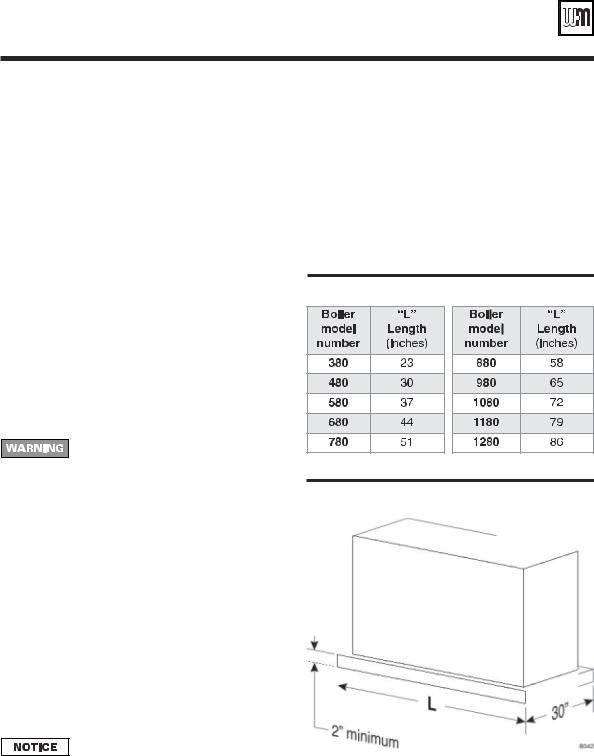
Floor construction and condition must be suitable for weight of boiler when filled with water. See page 34 for approximate boiler operating weight.
A level concrete or brick foundation (constructed per Table 1 and Figure 1) is required when:
1.A floor could possibly become flooded.
2.Non-level conditions exist.
Table 1 Boiler foundation (see Figure 3)
Figure 1 Boiler foundation
Provide clearance around boiler
•Provide minimum clearances to combustible materials:
1.Singlewall vent pipe – 18 inches.
2.Doublewall vent pipe – refer to vent pipe manufacturer's recommendations for vent pipe clearances.
3.Boiler top — 24 inches.
4.Boiler front — 48 inches.
5.Boiler flue — 9 inches.
6.Boiler rear — 9 inches.
7.Boiler sides — 6 inches.
•Boiler may be installed on combustible flooring.
•See pages 34 and 35 for boiler dimensions.
Flue pipe/breeching clearances take precedence over jacket clearances.
•Left side — for cleaning and tankless heater removal – 34 inches.
•Allow sufficient space on remaining sides for cleaning, servicing and burner installation. See burner literature for length and recommended service clearances.
Part No. 550-141-935/0602 |
3 |
Weil-McLain 80 Boiler For Gas, Light Oil, Gas/Light Oil Fired Burners
1 Before installing boiler (continued)
Provide combustion and ventilation air openings:
Do not install an exhaust fan in boiler room. Adequate combustion and ventilation air must be provided to assure proper combustion and prevent possibility of flue gas leakage and carbon monoxide emissions, causing severe personal injury or death.
Opening sizes must comply with state, provincial or local codes. In their absence, use the following when boiler is in a confined room:
•Provide two permanent openings in boiler room — one within 12 inches of ceiling, one within 12 inches of floor. Minimum dimension of each opening is 3 inches.
1.When all air is taken from within building, each opening should be at least one square inch/1,000 Btuh boiler input and freely connect with areas having adequate infiltration from outside.
2.When all air is taken from outdoors, each opening should connect directly or by ducts from outdoors or crawl or attic spaces that freely connect with outdoors and sized as listed below:
a.through outside wall or vertical ducts - at least one square inch/4,000 Btuh boiler input.
b.through horizontal ducts - at least one square inch/2,000 Btuh boiler input.
c.where ducts are used, they should be same crosssectional area as free area of openings they are connected to.
d.compensate for louver, grille or screen blockage when calculating free air openings. Refer to their manufacturer's instructions for size. If unknown, use:
•wood louvers - 20-25% free air.
•metal louvers or grilles - 60-75% free air.
•screens - not less than ¼ inch mesh.
Lock louvers in open position, or interlock with equipment to prove open before boiler operation.
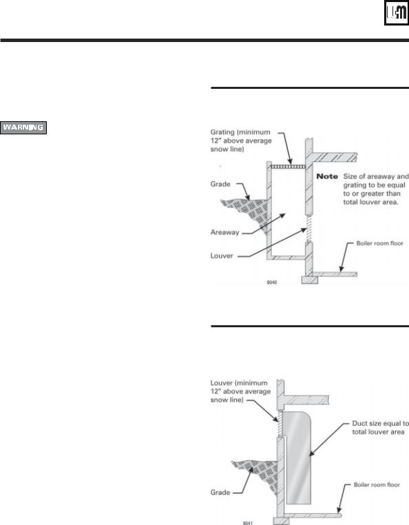
When combustion and ventilation air enters through sidewall openings, ensure openings comply with Figures 2 and 3.
Figure 2 Combustion and ventilation air openings — Boiler room below grade
Figure 3 Combustion and ventilation air openings — Boiler room partially or completely above grade
4 |
Part No. 550-141-935/0602 |
• Installation • Start-Up • Maintenance • Parts
2 Set boiler in place
For packaged boiler:
1.Remove top jacket panels. Set aside until after boiler is piped.
The boiler contains ceramic fiber and fiberglass materials. Use care when handling these materials per instructions on page 38 of this manual. Failure to comply could result in severe personal injury.
2.Remove lag screws (2 in front, 2 in rear) from shipping rails.
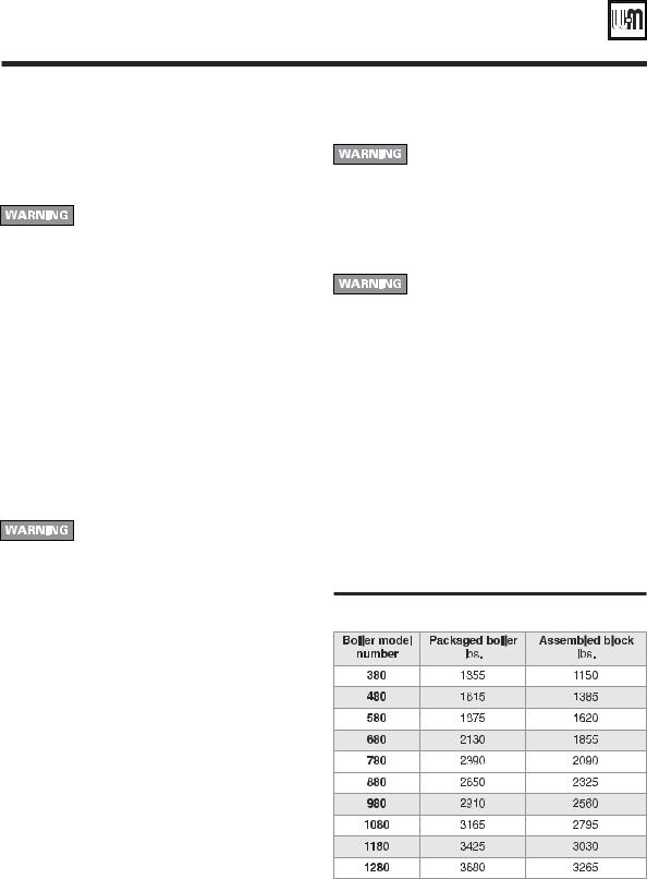
3.Remove boiler from skid. Cables are already attached to block assembly. See Table 2 for lifting weight.
•Using crane — hook middle of each cable to eye of crane.
•Using hoist — hook middle of each cable to hoist. Raise boiler off skid. Use pipe rollers under skid angles to roll boiler.
4.Place boiler in final position. Center boiler on foundation, if used.
5.Level boiler. Shim under skid angles, if necessary.
6.Cut off cables.
Cables are not intended for long-term usage. Cables may corrode inside boiler, weakening their lifting strength. Failure to remove cables can result in severe personal injury, death or substantial property damage.
7. Proceed to "Perform hydrostatic pressure test," page 8.
Cables are not intended for long-term usage. Cables may corrode inside boiler, weakening their lifting strength. Failure to remove cables can result in severe personal injury, death or substantial property damage.
6.Inspect block assembly for disjointed sections. Check gas-tight seal of flue collector hood and cleanout plates.
Gas tight seal must be maintained to prevent possible flue gas leakage and carbon monoxide emissions, resulting in severe personal injury or death.
a.Check inside section assembly for any light passing through unsealed areas.
b.Mark all unsealed areas.
c.At unsealed areas, check for:
•damaged gaskets.
•sealing rope not in place.
•loose bolts or nuts.
d.Correct all conditions and repeat step b. If unsealed areas still exist, contact your Weil-McLain distributor or sales office before continuing installation.
7.Proceed to "Perform hydrostatic pressure test," page 8.
Table 2 Lifting weights
For block assembly:
1. Remove lag screws (2 in front, 2 in rear) from shipping rails.
2.Remove boiler from skid. Cables are already attached to block assembly. See Table 2 for lifting weight.
• Using crane – attach free end of cables to eye of crane.
•Using hoist – attach free end of cables to hoist. Raise boiler off skid. Use pipe rollers under steel skid
angles to roll boiler.
3.Place boiler in final position. Center boiler on foundation, if used.
4.Level boiler. Shim under skid angles, if necessary.
5.Cut off cables.
Part No. 550-141-935/0602 |
5 |
Weil-McLain 80 Boiler For Gas, Light Oil, Gas/Light Oil Fired Burners
3 Assemble block
Sections are top heavy. Unbolted sections may fall if not supported, resulting in severe personal injury or death.
Install back refractory blanket
1.Lay back section on floor with ports face up.
2.Apply adhesive to blanket.
3.Press blanket against back target wall as shown in Figure 4.
4.Using knife, cut hole through blanket to expose observation port opening.
Prepare back section
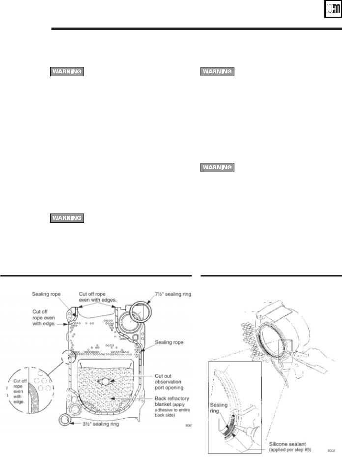
1.Apply 1/8" continuous bead of sealing rope adhesive in sealing rope grooves. See Figure 4. Do not get any adhesive on machined port surfaces.
2.Place ½" sealing rope in groove. Around curves, grasp at 1" intervals and push together. Do not stretch.
Do not pre-cut rope. Gas tight seal must be maintained to prevent possibility of flue gas leakage and carbon monoxide emissions, causing severe personal injury or death.
3.Remove any grit from port machined surfaces with clean rag.
Do not use petroleum-based cleaning or sealing compounds in boiler system. Severe damage to system components can result, causing substantial property damage.
4.Place 7½" and 3½" sealing rings in appropriate port openings. See Figure 4. If sealing ring slips out of groove, stretch ring gently for several seconds, then reposition in groove.
5.Apply continuous bead of silicone sealant no larger than 1/16" around entire outside edge of outer machined surface of port. Refer to Figure 5. Do not apply silicone sealant on, next to or under sealing ring.
Silicone sealant applied as specified above prevents unburned oil vapors from coming in contact with sealing ring.Vapor contact can damage rings, resulting in severe damage to boiler and substantial property damage.
6.Position section upright on foundation (if used) and screw 3" pipe at least 22" long into 3" return tapping.
7.Place a block under pipe to hold section upright.
Figure 4 Sealing rope installation |
Figure 5 Silicone sealant |
6 |
Part No. 550-141-935/0602 |
• Installation • Start-Up • Maintenance • Parts
3 Assemble block (continued)
Install intermediate sections
Sections are top heavy. Unbolted sections may fall if not supported, resulting in severe personal injury or death.
1.Remove and discard 3/8" diameter shipping tie rods.
2.Remove grit from port machined surfaces with clean rag.
Do not use petroleum-based cleaning or sealing compounds in boiler system. Severe damage to system components can result, causing substantial property damage.
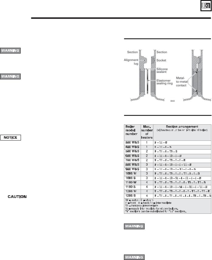
3.Position intermediate section so aligning lugs fit into sockets of next section. See Figure 6.
4.Install TI (tankless intermediate) and SI (supply intermediate) sections (when used) in order shown in Table 3.
5.Draw sections together until metal-to-metal contact is made around machined port openings (see Figure 6):
a.Oil threads on 4 draw rods. Install washer and nut on end to be tightened. Use nut only on other end.
b.Uniformly draw sections together, starting at washer/nut end.
Important — Leave an equal amount of thread on each end of the draw rod. This is needed to allow securing the jacket support brackets in place (see pages 20 and 21).
c.Draw rods should be torqued to a range of 90 to 100 ft. - lbs. Do not back off draw rods.
d.Metal-to-metal contact will be achieved around port openings. See Figure 6. If gap occurs, it should be no greater than .032". Check with feeler gauge.
e.If, for any reason, gap around machined port opening exceeds .032", check for rope extending from rope grooves, dirt on port openings or sockets, or misaligned lugs. If corrections are made and gap still exists, contact your Weil-McLain distributor or sales office before continuing installation.
6. |
|
After erecting first intermediate section, check both |
|
||
|
|
sections for plumb. Failure to plumb sections can cause |
|
|
|
|
|
misaligned piping and breeching, possibly resulting in |
|
|
property damage. |
7. Repeat steps 1-5 from “Prepare back section,” page 6.
Install bottom refractory blanket on combustion chamber floor inside section block
1.Unroll blanket only to depth of back section and first intermediate section.
2.Spread adhesive on bottom side of blanket.
3.Press blanket into center bottom of sections.
4.Unroll and install blanket per steps 2 and 3 as each intermediate and front section are installed.
5.At front section, cut off blanket 2 ½" from burner opening. Discard unused blanket.
Figure 6 Sealing ring installation and port alignment
Table 3 Section arrangement
Do not use petroleum-based cleaning or sealing compounds in boiler system. Severe damage to system components can result, causing substantial property damage.
b.Check each section for proper sealing rope position before proceeding to next section.
Failure to position sealing rope properly can cause boiler to not seal gas-tight. Gas tight seal prevents possible flue gas leakage and carbon monoxide emissions, resulting in severe personal injury or death.
Prepare remaining sections
1. Follow“Prepare intermediate section”for remaining intermediate and front |
If using tankless heater (TI) sections |
|
|
sections: |
1. Install tankless heaters and gaskets or heater cover plates |
a. Remove any grit from threads inside tapped holes with clean rag. |
and gaskets. Use 3/8" x 3/4" studs, washers and nuts. |
Part No. 550-141-935/0602 |
7 |

Weil-McLain 80 Boiler For Gas, Light Oil, Gas/Light Oil Fired Burners
4 Perform hydrostatic pressure test
Prepare boiler and test:
1.See pages 28 and 29 for tapping locations. Install:
a.Boiler drain (not furnished).
b.Water pressure gauge — for test only. Be sure gauge can handle test pressure — see step 3.
c.Air vent in upper tapping (K).
2.Plug remaining tappings.
Do not pressure test with any control installed. Damage to control can occur due to overpressure.
3.Fill boiler. Vent all air. Pressure test at least 10 minutes at a pressure not less than the following: Steam boiler:
Between 45 and 55 psig. Water boiler:
1½ times maximum allowable working pressure (MAWP) stamped on the boiler nameplate, located on boiler jacket front panel.
 Do not exceed above test pressures by more than 10 psig.
Do not leave boiler unattended. Cold water fill could expand and cause excessive pressure, resulting in severe personal injury, death or substantial property damage.
4. Check for maintained gauge pressure and leaks. Repair if found.
Leaks must be repaired at once. Failure to do so can damage boiler, resulting in substantial property damage.
Do not use petroleum-based cleaning or sealing compounds in boiler system. Severe damage to system components can result, causing substantial property damage.
5.Drain boiler and remove air vent, boiler drain and gauge. Remove plugs from tappings that will be used for controls and accessories.
8 |
Part No. 550-141-935/0602 |

• Installation • Start-Up • Maintenance • Parts
5 Complete block assembly
Install burner mounting plate on front section
1.Install four ½" x 4¾" studs to secure burner mounting plate to section:
a.Thread and lock together two nuts on rounded end of stud. Thread flat end of stud into one of four holes located around opening.
b.Remove nuts.
c.Repeat steps a and b for remaining studs.
2.Install burner mounting plate:
a.Apply 1/8" continuous bead of sealing rope adhesive in groove around opening in section.
b.Position ½" sealing rope in groove. Overlap ends at least one inch.
c.Install burner mounting plate. Use ½" washers and nuts.
Install observation port assemblies on front and back sections:
1.Install front observation port assembly:
a.Apply 1/8" continuous bead of sealing rope adhesive in groove on observation port.
b.Position 3/8" sealing rope in groove.
c.Secure assembly to section. Use 5/16 " - 18 x ¾" slotted head screws.
2.Repeat above steps for back observation port assembly.
Install cleanout plates
Cleanout plates must be installed gas-tight to prevent possibility of flue gas leakage and carbon monoxide emissions, resulting in severe personal injury or death.
1.See Figure 7. Position two ¼" x 1¾" carriage bolts in cleanout opening. Secure with washers and nuts.
2.Place blanket insulation piece against cleanout plate.
3.Mount cleanout plate over opening. Secure with nuts and washers.
4.Repeat steps 1 through 3 for remaining cleanout plates.
|
The boiler contains ceramic fiber and |
Figure 7 Cleanout plate assembly |
|
||
|
fiberglass materials. Use care when |
|
|
|
|
|
handling these materials per |
|
|
instructions on page 38 of this |
|
|
manual. Failure to comply could |
|
|
result in severe personal injury. |
|
Part No. 550-141-935/0602 |
9 |
Weil-McLain 80 Boiler For Gas, Light Oil, Gas/Light Oil Fired Burners
6 Install flue collector
Flue collector assembly
1.Figure 10, page 11, shows flue collector components and locations. Figure 11, page 13, shows collector hoods for all models. Follow all instructions in this manual to ensure correct installation of the flue collector.
2.Model 80 boilers are available with either rear flue or top flue. Verify that you have the correct components for your application. You can convert a Model 80 from rear to top or top to rear flue using a flue conversion kit, available from your Weil-McLain distributor.
The flue outlet for top flue models must be located as shown in this manual.
Install collector hold-down bolts
1.Figure 10, lower left — Install a collector hold-down bolt assembly at each section joint, and on both sides of the boiler section assembly. Set aside the flanged nuts for securing the collector assembly when it is ready.
2.Each hold-down bolt assembly consists of a 5/16" x 2" carriage bolt, flat washer, regular hex nut and a flanged nut as shown.
Prepare flue collector hood assembly
Make sure gaskets are intact, not torn or otherwise damaged. These conditions can cause possible flue gas leakage and carbon monoxide emissions, resulting in severe personal injury or death.
The boiler contains ceramic fiber and fiberglass materials. Use care when handling these materials per instructions on page 38 of this manual. Failure to comply could result in severe personal injury.
1.Stand flue collector hood front module (item 4) on end as in Figure 8, left side.
Figure 8 Collector hood preparation
2.Wipe all flanged surfaces with clean rag.
3.Lay flue collector hood gasket (item 2) on flange.
4.Place flue collector end cap (item 1) on gasket. Align bolt holes. Secure with seven 5/16" x 5/8" flanged bolts and flanged nuts. Tighten to between 30 and 35 inch-pounds torque. (See WARNING on page 12, top right column.)
5.For 880 - 1280:
a.Stand remaining hood module on end, as in Figure 8, right side.
b.Wipe all flanged surfaces with clean rag.
c.Lay gasket on flange.
d.Carefully place open end of first module on top of gasket, aligning flanged surfaces.
e.Secure with seven 5/16" x 5/8" flanged bolts and flanged nuts.Tighten to between 30 and 35 inchpounds torque. (See WARNING on page 12.)
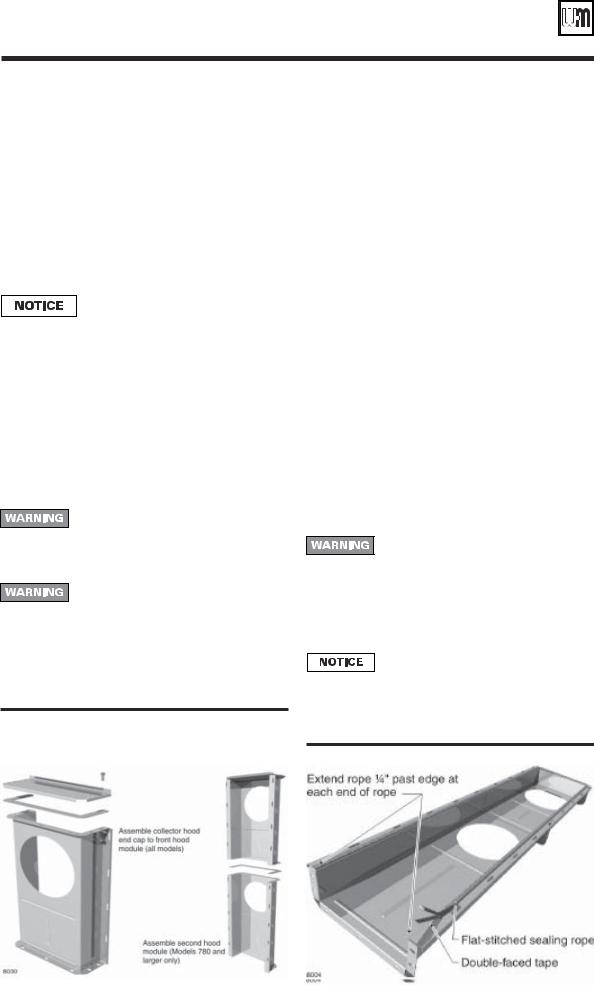
6.Attach flat-stitched sealing rope to hood assembly. See Figure 9:
a.Lay hood on floor with flanged side up.
b.Wipe flanged surface with clean rag to remove dirt and oil.
c.Apply double-faced tape to flanged surface.
d.Apply rope to tape beginning on one side of open end of hood, leaving ¼" extending past edge. Bend rope around corners. DO NOT cut or stretch rope.
Do not pre-cut rope. All collector hood joints must be sealed gas-tight to prevent possible flue gas leakage and carbon monoxide emissions, resulting in severe personal injury or death.
e.Continue around entire flange. At other open end, leave ¼" rope extending past edge of flange. Cut off excess rope.
Double-faced tape serves only to hold sealing rope in place during installation. It will disintegrate over time. If collector hood and sealing rope are removed for any reason, install new tape and new gasket.
Figure 9 Flue collector sealing rope installation
10 |
Part No. 550-141-935/0602 |

• Installation • Start-Up • Maintenance • Parts
6 Install flue collector (continued)
Figure 10 Flue collector components, typical (Model 880 collector configurations shown)
Part No. 550-141-935/0602 |
11 |

Weil-McLain 80 Boiler For Gas, Light Oil, Gas/Light Oil Fired Burners
6 Install flue collector (continued)
Before installing flue collector
1.See Figure 10, page 11, for general assembly of flue collector components.
2.See Figure 11, page 13 for the placement of flue collector hoods on each model.
3.Prepare mounting holes in boiler rear section.
a.The boiler rear section has tapped holes for mounting rear flue collector component.
b.Remove any grit from threads inside tapped holes with clean rag.
Rear flue boilers only:
1.See Figure 10, page 11 and Figure 11, page 13.
2.Place collector hood transition on rear section:
a.Wipe item 10, Figure 10, collector hood transition flange surfaces with a clean rag.
b.Apply a few pieces of double-faced tape on the collector hood transition flange.
c.Place the collector hood transition gasket (item 8, Figure 10) on the collector hood transition flange. Align holes in gasket with holes in flange. Press gasket firmly in place.
d.Position collector hood transition on back of boiler rear section, aligning collector hood transition flange holes with tapped holes in boiler rear section.
e.Insert a 5/16" x 5/8" flanged bolt through the bottom center hole and finger tighten to hold transition in place.
f.Install six remaining bolts securing collector hood transition to rear section. Finger-tighten only.
3.Place collector hood assembly on sections:
a.Carefully set collector hood assembly on top of section assembly. Align slotted holes in collector hood flanges with the hold-down bolts in the sections.
b.Place the collector hood assembly so its rear flange is against the collector hood transition flange gasket.
c.Thread flanged nuts onto hold-down bolts and fingertighten only.
d.Insert five 5/16" x 5/8" flanged bolts through holes in collector hood transition and collector hood assembly rear flange. Thread on nuts and finger-tighten only.
4.Tighten flue collector bolts and nuts:
a.Gradually tighten all bolts and nuts on flue collector assembly and boiler. Tighten to between 30 and 35 inch-pounds torque. See WARNING, upper right.
b.Alternate locations as you tighten the fasteners to ensure all parts are evenly drawn down, with no gaps or distortion of parts.
5.Install damper and flue caps:
a.Wipe item 5, Figure 10, flue damper flange surface with a clean rag.
b.Apply a few pieces of double-faced tape to the flue damper flange. Position flue collar gasket on damper and press firmly in place. Align all holes before securing.
c.Position flue damper assembly against collector hood transition. Insert a #10 x ½" screw through the top center hole. Lightly tighten to hold flue damper in position.
d.Insert remaining #10 screws into flue damper flange and lightly tighten. Alternate from screw to screw and tighten all screws evenly and securely.
e.Install flue caps on flue collector top opening(s) using steps 5a through 5d.
DO NOT overtighten bolts in flue collector hood assembly. Gasket material could extrude, causing possible flue gas leakage and carbon monoxide emissions, resulting in severe personal injury or death.
Top flue boilers only:
1.See Figure 10, page 11 and Figure 11, page 13.
2.Place rear flue cap on rear section:
a.Wipe item 9, Figure 10, rear flue cap gasket surface with a clean rag.
b.Apply a few pieces of double-faced tape on the rear flue cap gasket surface.
c.Place the rectangular gasket (item 8, Figure 10) on the flue cap, aligning holes in gasket with holes in rear flue cap. Press firmly in place.
d.Position rear flue cap on back of boiler rear section, aligning rear flue cap holes with tapped holes in boiler rear section.
e.Insert a 5/16" x 5/8" flanged bolt through the bottom center hole and finger tighten to hold rear flue cap in place.
f.Install six remaining bolts securing rear flue cap to rear section. Fingertighten only.
3.Place collector hood assembly on sections:
a.Carefully set collector hood assembly on top of section assembly. Align slotted holes in collector hood flanges with the hold-down bolts in the sections.
b.Place the collector hood assembly so its rear flange is against the rear flue cap gasket.
b.Thread flanged nuts onto hold-down bolts and finger-tighten only.
c.Insert five 5/16" x 5/8" flanged bolts through holes in rear flue cap and collector hood assembly rear flange. Thread on nuts and finger-tighten only.
4.Tighten flue collector bolts and nuts:
a.Gradually tighten all bolts and nuts on flue collector assembly and boiler.
Tighten to between 30 and 35 inch-pounds torque. See WARNING, above.
b.Alternate locations as you tighten the fasteners to ensure all parts are evenly drawn down, with no gaps or distortion of parts.
5.Install damper and flue caps (see Figure 11, page 13):
a.Wipe item 5, Figure 10, flue damper flange surface and flue collector assembly surfaces with a clean rag.
b.Position round gasket (item 7, Figure 10) on flue collector assembly in the flue location shown in Figure 11, page 13. Align bolt holes.
c.Place flue damper assembly on gasket. (See NOTICE, below.) Insert #10 x ½" screws through the holes. Alternate from screw to screw and tighten all screws evenly and securely.
Model 380 top flue applications — always mount the damper assembly with the damper adjustment plate pointed toward the rear of the boiler as shown in Figure 11. Otherwise, the jacket top panels may be difficult to install.
e.Install flue cap on remaining top opening (if any) using steps a through c, above.
After installing flue collector, ALL BOILERS
1. Check for gas-tight seal of all flue collector hood components.
All collector hood joints must be sealed gas-tight to prevent possible flue gas leakage and carbon monoxide emissions, resulting in severe personal injury or death.
a.Open flue damper.Visually inspect inside section assembly and flue collector assembly for any light passing through unsealed areas.
b.Mark all unsealed areas.
c.Check unsealed areas for cause — damaged gaskets, sealing rope not in place, or loose bolts or nuts.
d.Correct all conditions and repeat inspection procedure.
e.If unsealed areas cannot be eliminated, discontinue the boiler installation. Contact your Weil-McLain distributor or sales office for assistance.
12 |
Part No. 550-141-935/0602 |
 Loading...