


Gas-fired water boiler
Ultra-80, -105, -155, -230 & -310
• Installation
• Startup
• Maintenance
• Parts
with
This manual must only be used by a qualified heating installer/service technician. Read all instructions, including this manual, the Ultra Control Supplement and the Ultra Vent Supplement, before installing. Perform steps in the order given. Failure to comply could result in severe personal injury, death or substantial property damage.
Part number 550-101-233/0903

|
GAS-FIRED WATER BOILER — Boiler Manual |
THE |
BOILER, WITH PhD TECHNOLOGY – HOW IT WORKS . . . |
PhDtechnology
PhD Technology, Precision hydronic Data, is an intelligent system that delivers Precision hydronic heating and hot water needs while maximizing efficiency by measuring the Data parameters of your heating system.
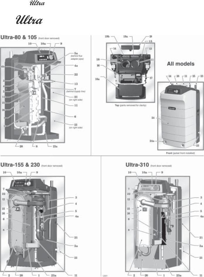
1.Cast aluminum heat exchanger
2.Heat exchanger access cover
3.Blower
The advanced blower design and air inlet silencer (5a) on Ultra boilers result in very quiet operation.
80 & 105 — Air enters the boiler enclosure through the air intake adapter (18), flows through the enclosure, enters the air inlet silencer (5a), then enters the blower. The blower pulls air through the silencer and pushes it into the venturi (5), where it mixes with gas before entering the burner.
155, 230 & 310 — Air enters the boiler enclosure through the air intake adapter (18), flows through the enclosure, enters the air inlet silencer (5a), then enters the venturi (5). The blower pulls air and gas through the venturi and pushes the mixture into the burner.
4.Gas valve
The gas valve senses the vacuum in the venturi caused by flowing air, and allows gas to flow when power is applied. The manual gas valve (4a) allows shutting off the gas supply for servicing or shutdown. Models 80 and 105 use a sensing line (4b) from the gas valve to the blower outlet so the gas valve references the same pressure as the venturi inlet.
12.Burner
Made with high-grade stainless steel construction, the burner uses pre-mixed air and gas and provides a wide range of firing rates.
13.Water outlet pipe (system supply)
14.Water return pipe (system return)
15.Gas connection pipe
16.Control Module
The Control Module responds to signals from the room thermostat, supply water sensor, return water sensor, flue gas sensor and (if used): domestic hot water aquastat, outdoor temperature sensor, and summer/winter switch. The control module automatically adjusts blower speed (and gas flow rate) to match boiler output to space heating and/or DHW heating demand. The control module is accessed by removing top front cover (16a).
17.Transformer
The transformer reduces line voltage from 120 vac to 24 vac, providing 24 vac to the control module for the gas valve and blower signal .
18.Air intake adapter
19.Electrical entrance cover plate
5.Venturi
When air flows through the venturi, it creates a vacuum. This vacuum pulls gas from the gas valve. So gas will only flow if air is flowing. On 80 and 105 models, the gas air mixture enters the burner after the venturi. On 155, 230 and 310 models, the gas/air mixture enters the blower before passing on to the burner.
6.Flue gas sensor
This sensor monitors the flue gas exit temperature. The control module will shut down the boiler if flue gas temperature gets too hot. This protects the flue pipe and the heat exchanger from overheating.
7.Outlet water temperature sensor
This sensor monitors boiler outlet water temperature (system supply). The control module adjusts boiler firing rate so the outlet temperature is correct.
8.Return water temperature sensor
This sensor monitors return water temperature (system return). The control module reduces or increases boiler input, depending on how close the return water temperature is to the outlet water temperature.
9.Temperature and pressure gauge
10.Electronic display & buttons
The 4-digit electronic display is used to:
•Set space heating temperature.
•Show outlet water temperature (normal) or other operating conditions (in Information mode).
•Show boiler status and shutdown or lockout codes for easy troubleshooting.
The buttons allow changing display mode and reset after lockout. The on/off Power switch (10a) turns power to the boiler controls on or off.
11. Flue pipe adapter
Remove the electrical cover plate to access the line voltage terminal strip (19b) and the low voltage terminal strip (19a). Attach line voltage conduits to the three holes at the left of the line voltage terminal strip for power, CH pump and DHW pump. Route low voltage wires through the opening to the right of the low voltage terminal strip.
20.Boiler drain valve
21.Line voltage receptacle
Use this connection to plug in line voltage meters or tools while working on boiler. Do not exceed 10-amp load.
22.P/T gauge temperature sensor well
The remote sensor for the panel-mounted pressure/temperature gauge inserts into the outlet water pipe here.
23.Flue gas condensate drain connection
Connect condensate drain line to ½" PVC tee here. The condensate trap (23a) and PVC fittings are field-installed.
24.Front door
The front door is sealed to the boiler assembly around its entire perimeter. Two knurled-head screws (24a) secure the door in place.
25.Ignition electrode
The burner flame is ignited by applying a high voltage to the ignition electrode. This causes a spark (from electrode to ground).
26.Flame inspection window
The quartz glass window provides a view of the burner surface and flame.
2 |
Part number 550-101-233/0903 |
|
GAS-FIRED WATER BOILER — Boiler Manual |
|
|
|
|
THE |
GAS-FIRED WATER BOILER, WITH PhD TECHNOLOGY |
Part number 550-101-233/0903 |
3 |


 GAS-FIRED WATER BOILER — Boiler Manual
Contents
How it works.................................................................................... |
2–3 |
||
Hazard definitions .............................................................................. |
4 |
||
Please read before proceeding ........................................................ |
5 |
||
1 |
|
Prepare boiler location .................................................................. |
6 |
2 |
|
Prepare boiler ................................................................................. |
9 |
3 |
|
Install water piping ....................................................................... |
12 |
4 |
|
Venting, combustion air & condensate line .............................. |
19 |
5 |
|
Gas piping ..................................................................................... |
21 |
6 |
Startup (Note 1) ................................................................................. |
23 |
|
7 |
|
Check-out/startup verification .................................................... |
26 |
8 |
|
Annual startup and general maintenance ................................ |
28 |
9 |
|
Replacement parts ....................................................................... |
35 |
10 |
Dimensions ................................................................................. |
43 |
|
11 |
Ratings ........................................................................................ |
44 |
|
Note 1: See Ultra Control Supplement for wiring and additional startup and operating information.
Hazard definitions
The following defined terms are used throughout this manual to bring attention to the presence of hazards of various risk levels or to important information concerning the life of the product.
Indicates presence of hazards that will cause severe personal injury, death or substantial property damage.
Indicates presence of hazards that can cause severe personal injury, death or substantial property damage.
Indicates presence of hazards that will or can cause minor personal injury or property damage.
Indicates special instructions on installation, operation or maintenance that are important but not related to personal injury or property damage.
4 |
Part number 550-101-233/0903 |


 GAS-FIRED WATER BOILER — Boiler Manual
Please read before proceeding
Installer— Read all instructions, including this manual, the Ultra Control Supplement and Ultra Vent Supplement, before installing. Perform steps in the order given.
User — This manual is for use only by a qualified heating installer/service technician. Refer to User’s Information Manual for your reference.
User — Have this boiler serviced/ inspected by a qualified service technician, at least annually.
Failure to comply with the above could result in severe personal injury, death or substantial property damage.
The boiler contains ceramic fiber materials. Use care when handling these materials per instructions on page 29 of this manual. Failure to comply could result in severe personal injury.
When calling or writing about the boiler— Please have the boiler model number from the boiler rating label and the CP number from the boiler jacket.You may list the CP number in the space provided on the Installation and service certificate found on page 27.
Consider piping and installation when determining boiler location.
Any claims for damage or shortage in shipment must be filed immediately against the transportation company by the consignee.
Commonwealth of Massachusetts
When the boiler is installed within the Commonwealth
of Massachusetts:
•This product must be installed by a licensed plumber or gas fitter.
•If antifreeze is used, a reduced pressure back-flow preventer device shall be used.
Failure to adhere to the guidelines on this page can result in severe personal injury, death or substantial property damage.
When servicing boiler —
•To avoid electric shock,disconnect electrical supply before performing maintenance.
•To avoid severe burns, allow boiler to cool before performing maintenance.
Boiler operation —
•Do not block flow of combustion or ventilation air to boiler.
•Should overheating occur or gas supply fail to shut off, do not turn off or disconnect electrical supply to circulator. Instead, shut off the gas supply at a location external to the appliance.
•Do not use this boiler if any part has been under water. Immediately call a qualified service technician to inspect the boiler and to replace any part of the control system and any gas control that has been under water.
Boiler water —
•The Ultra heat exchanger is made of aluminum, and requires that system pH always be between 7.0 and 8.5 and water chemistry be checked.Chemical treatment may be necessary.See page 24 for details.
•Thoroughly flush the system (without boiler connected) to remove sediment. The high-efficiency heat exchanger can be damaged by build-up or corrosion due to sediment.
•Do not use petroleum-based cleaning or sealing compounds in boiler system. Gaskets and seals in the system may be damaged. This can result in substantial property damage.
•Do not use“homemade cures”or“boiler patent medicines.”Serious damage to boiler, personnel and/or property may result.
•Continual fresh make-up water will reduce boiler life. Mineral buildup in heat exchanger reduces heat transfer, overheats the aluminum heat exchanger, and causes failure. Addition of oxygen carried in by make-up water can cause internal corrosion. Leaks in boiler or piping must be repaired at once to prevent make-up water.
•Do not add cold water to hot boiler. Thermal shock can cause heat exchanger to crack.
Freeze protection fluids —
NEVER use automotive or standard glycol antifreeze, even glycol made for hydronic systems. Use only freeze-protection fluids recommended in the Ultra Boiler Freeze Protection Supplement.
Follow all guidelines in the Ultra Boiler Freeze Protection Supplement. Thoroughly clean and flush any replacement boiler system that has used glycol before installing the new Ultra boiler.
Part number 550-101-233/0903 |
5 |
1 |
GAS-FIRED WATER BOILER — Boiler Manual |
|
Prepare boiler location
Installations must comply with:
•Local, state, provincial, and national codes, laws, regulations and ordinances.
•National Fuel Gas Code, ANSI Z223.1 – latest edition.
•Standard for Controls and Safety Devices for Automatically Fired Boilers, ANSI/ASME CSD-1, when required.
•National Electrical Code.
•For Canada only: B149.1 or B149.2 Installation Code, CSA C22.1 Canadian Electrical Code Part 1 and any local codes.
The Ultra boiler gas manifold and controls met safe lighting and other performance criteria when boiler underwent tests specified in ANSI Z21.13 — latest edition.
Before locating the boiler, check:
1.Check for nearby connection to:
•System water piping
•Venting connections
•Gas supply piping
•Electrical power
2.Check area around boiler. Remove any combustible materials, gasoline and other flammable liquids.
Failure to keep boiler area clear and free of combustible materials, gasoline and other flammable liquids and vapors can result in severe personal injury, death or substantial property damage.
3.The Ultra boiler must be installed so that gas control system components are protected from dripping or spraying water or rain during operation or service.
4.If new boiler will replace existing boiler, check for and correct system problems, such as:
•System leaks causing oxygen corrosion or heat exchanger cracks from hard water deposits.
•Incorrectly-sized expansion tank.
•Lack of freeze protection in boiler water causing system and boiler to freeze and leak.
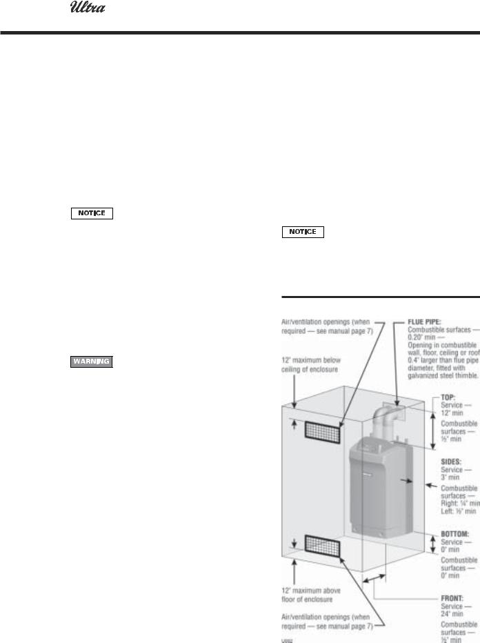
Provide clearances:
Clearancesfromcombustiblematerials
1.Hot water pipes — at least ½" from combustible materials.
2.Vent pipe — at least 0.20" from combustible materials.
3.See Figure 1 for other clearance minimums.
Clearancesforserviceaccess
1.See Figure 1 for recommended service clearances. If you do not provide minimum clearances shown, it might not be possible to service the boiler without removing it from the space.
Ultra boilers, except the Ultra-310, may be wall mounted (using special wall mount kit) or floor mounted. No clearance is required at the rear of the unit, either for service or for clearance to combustible surfaces.
Figure 1 Clearances required
6 |
Part number 550-101-233/0903 |
1 |
GAS-FIRED WATER BOILER — Boiler Manual |
|
Prepare boiler location (continued)
Flooring and foundation
Flooring
The Ultra boiler is approved for installation on combustible flooring, but must never be installed on carpeting.
Do not install boiler on carpeting even if foundation is used. Fire can result, causing severe personal injury, death or substantial property damage.
Foundation
Provide a solid foundation pad, at least 2 inches above the floor, if any of the following is true:
•floor can become flooded.
•the floor is dirt, sand, gravel or other loose material.
•the boiler mounting area is severely uneven or sloped.
The minimum foundation size is:
•Ultra-80 to -230: 24 inches wide x 20 inches deep.
•Ultra-310: 24 inches wide x 23 inches deep
24 inches x 20 inches.Foundation may be of wood, brick or concrete (minimum 2 inches thick) construction.
If flooding is possible, elevate boiler sufficiently to prevent water from reaching boiler.
Ultra boiler in same space with other gas or oil-firedappliances
1.Follow the National Fuel Gas Code (U. S.) or CSA B149.1 and B149.2 (Canada) to size/verify size of the combustion/ventilation air openings into the space.
The space must be provided with combustion/ventilation air openings correctly sized for all other appliances located in the same space as the Ultra boiler.
Replace boiler jacket front door after servicing. The boiler front door must be securely fastened to the boiler to prevent boiler from drawing air from inside the boiler room. This is particularly important if the boiler is located in the same room as other appliances.
Failure to comply with the above warnings could result in severe personal injury,death or substantial property damage.
2.Size openings only on the basis of the other appliances in the space. No additional air opening free area is needed for the Ultra boiler because it takes its combustion air from outside (direct vent installation).
Residential garage installation
Precautions
Take the following special precautions when installing the boiler in a residential garage. If the boiler is located in a residential garage, per ANSI Z223.1, paragraph 5.1.9:
•Mount the boiler with a minimum of 18 inches above the floor of the garage to the bottom of the boiler to ensure the burner and ignition devices will be no less than 18 inches above the floor.
•Locate or protect the boiler so it cannot be damaged by a moving vehicle.
Provide air openings to room:
Ultra boiler alone in boiler room
1.No air ventilation openings into boiler room are needed when clearances around Ultra boiler are at least equal to the SERVICE clearances shown in Figure 1. For spaces that do NOT supply this clearance, provide two openings as shown in Figure 1. Each opening must provide 1 square inch free area per 1,000 Btuh of boiler input.
Vent and air piping
The Ultra boiler requires a special vent system, designed for pressurized venting. Ultra boilers are rated ANSI Z21.13 Category IV (pressurized vent, likely to condense in the vent).
You must also install air piping from outside to the boiler air intake adapter.The resultant installation is categorized as direct vent (sealed combustion). Note prevention of combustion air contamination on page 8 when considering vent/air termination.
Vent and air must terminate near one another and may be vented vertically through the roof or out a side wall. You may use any of the vent/air piping methods covered in the Ultra Boiler Vent Supplement, included in the envelope assembly. Do not attempt to install the Ultra boiler using any other means.
Be sure to locate the boiler such that the vent and air piping can be routed through the building and properly terminated. The vent/air piping lengths, routing and
Part number 550-101-233/0903 |
7 |

1 |
GAS-FIRED WATER BOILER — Boiler Manual |
|
Prepare boiler location (continued)
Prevent combustion air contamination
Install air inlet piping for the Ultra boiler as described in the Ultra BoilerVent Supplement. Do not terminate vent/ air in locations that can allow contamination of combustion air. Refer to Table 1 for products and areas which may cause contaminated combustion air.
You must pipe combustion air to the boiler air intake. Ensure that the combustion air will not contain any of the contaminants below. Contaminated combustion air will damage the boiler, resulting in possible severe personal injury, death or substantial property damage. Do not pipe combustion air near a swimming pool, for example. Also avoid areas subject to exhaust fumes from laundry facilities. These areas will always contain contaminants.
Table 1 Corrosive contaminants and sources
When removing a boiler from existing common vent system:
Do not install the Ultra boiler into a common vent with any other appliance. This will cause flue gas spillage or appliance malfunction, resulting in possible severe personal injury, death or substantial property damage.
Failure to follow all instructions can result in flue gas spillage and carbon monoxide emissions, causing severe personal injury or death.
At the time of removal of an existing boiler, the following steps shall be followed with each appliance remaining connected to the common venting system placed in operation, while the other appliances remaining connected to the common venting system are not in operation.
a.Seal any unused openings in the common venting system.
b.Visually inspect the venting system for proper size and horizontal pitch and determine there is no blockage or restriction, leakage, corrosion or other deficiencies which could cause an unsafe condition.
c.Test vent system — Insofar as is practical, close all building doors and windows and all doors between the space in which the appliances remaining connected to the common venting system are located and other spaces of the building. Turn on clothes dryers and any appliance not connected to the common venting system. Turn on any exhaust fans, such as range hoods and bathroom exhausts, so they will operate at maximum speed. Do not operate a summer exhaust fan. Close fireplace dampers.
d.Place in operation the appliance being inspected. Follow the lighting instructions. Adjust thermostat so appliance will operate continuously.
e.Test for spillage at draft hood relief opening after 5 minutes of main burner operation. Use the flame of a match or candle, or smoke from a cigarette, cigar, or pipe.
f.After it has been determined that each appliance remaining connected to the common venting system properly vents when tested as outlined herein, return doors, windows, exhaust fans, fireplace dampers, and any other gas-burning appliance to their previous conditions of use.
Any improper operation of common venting system should be corrected so the installation conforms with the National Fuel Gas Code, ANSI Z223.1 — latest edition. Correct by resizing to approach the minimum size as determined using the appropriate tables in Part 11 of that code. Canadian installations must comply with B149.1 or B149.2 Installation Code.
8 |
Part number 550-101-233/0903 |
2 |
GAS-FIRED WATER BOILER — Boiler Manual |
|
Prepare boiler
Remove boiler from crate
Cold weather handling — If boiler has been stored in a very cold location (below 0°F) before installation, handle with care until the plastic components come to room temperature.
1.The Ultra boiler is generally easier to handle and maneuver after removing from crate.
2.After removing outer shipping carton from boiler, REMOVE jacket front door by loosening two knurledhead screws at lower front. Removing the door will prevent possible damage to the door during handling.
3.To remove boiler from pallet (after removing jacket front door):
a.Remove the four lag screws securing shipping brackets.
b.Unscrew the two rear boiler legs and remove the shipping brackets.
c.Replace legs.
d.Discard the cardboard protector insert on the rear of the boiler.
Do not drop boiler or bump jacket on floor or pallet. Damage to boiler can result.
Prepare for propane if operating on propane — Ultra-80 & -105
Ultra-80: DO NOT apply the following instructions to conversion of Ultra-80 boilers. Follow the instructions provided with the optional propane conversion kit. The propane conversion kit is NOT included as standard equipment for the Ultra-80.
Do not apply the following to conversion of a boiler already installed and connected to gas supply. For a boiler already installed, you must turn off gas supply, turn off power and allow boiler to cool before proceeding.You must also completely test the boiler after conversion to verify performance as described under“Startup,” Section 6 of this manual. See separate natural to propane conversion instructions for conversion of an existing boiler.
You must install the propane orifice to fire the Ultra boiler on propane.Verify when installing that the orifice size marking matches boiler size. Failure to comply could result in severe personal injury, death or substantial property damage.
Ultra-80-LP boilers are factory-equipped to operate on propane gas.
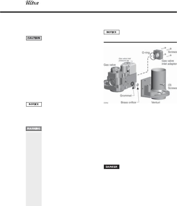
Figure 2 Installing propane orifice (Ultra-105)
1.With boiler on its back, remove jacket front door by removing two knurled head screws at lower front. Then lift door away from boiler.
2.Disconnect the gas valve electrical plug.
3.Remove the 4 screws securing gas valve inlet adapter to valve.
4.Remove (3) TORX screws securing gas valve to venturi (Figure 2).
5.Locate propane orifice disc from conversion kit bag.Verify that the stamping on the orifice disk matches the boiler size. Place orifice in the black rubber grommet in the side of the gas valve and secure in valve (Figure 2).
6.Reposition gas valve against venturi and replace (3) TORX screws securing valve to venturi. Secure gas valve inlet adapter to gas valve with 4 screws. Make sure the plastic hose is connected from gas valve to inlet elbow.
Inspect the O-ring between the gas valve and gas valve inlet adapter block whenever they are disassembled. The O-ring must be in good condition and must be installed. Failure to comply will cause a gas leak, resulting in severe personal injury or death.
7.DO NOT attempt to adjust gas valve outlet pressure.
8.Connect gas valve electrical plug to valve terminals.
9.After installation is complete, attach the propane conversion label (in conversion kit bag) next to the boiler rating plate.
10.Replace jacket front panel.
Part number 550-101-233/0903 |
9 |
2 |
GAS-FIRED WATER BOILER — Boiler Manual |
|
Prepare boiler (continued)
Prepare for propane if operating on propane — Ultra-155 to -230
Ultra-80: DO NOT apply the following instructions to conversion of Ultra-80 boilers. Follow the instructions provided with the optional propane conversion kit. The propane conversion kit is NOT included as standard equipment for the Ultra-80.
Do not apply the following to conversion of a boiler already installed and connected to gas supply. For a boiler already installed, you must turn off gas supply, turn off power and allow boiler to cool before proceeding.You must also completely test the boiler after conversion to verify performance as described under“Startup,” Section 6 of this manual. See separate natural to propane conversion instructions for conversion of an existing boiler.
You must install the propane orifice to fire the Ultra boiler on propane. Verify when installing that the orifice size marking matches boiler size. Failure to comply could result in severe personal injury, death or substantial property damage.
1.With boiler on its back, remove jacket front door by removing two knurled head screws at lower front. Then lift door away from boiler.
2.Disconnect the gas valve electrical plug.
3.Disconnect the gas line union below the gas valve.
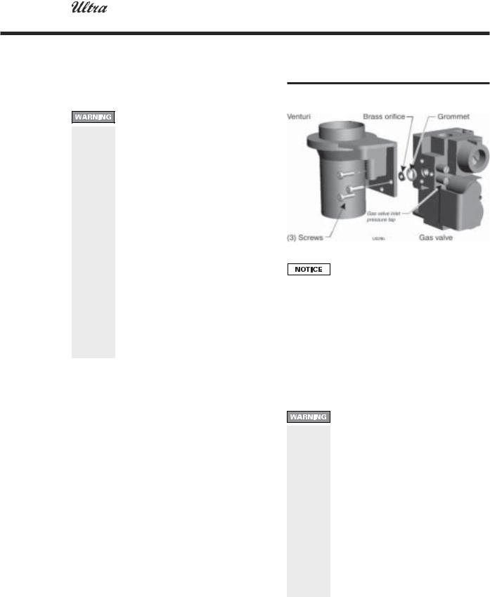
4.Remove (3) TORX screws securing gas valve to venturi (Figure 2a).
5.Locate propane orifice disc from conversion kit bag. Verify that the stamping on the orifice disk matches the boiler size. Place orifice in the black rubber grommet in the side of the gas valve and secure in valve (Figure 2).
6.Reposition gas valve against venturi and replace (3) TORX screws securing valve to venturi. Reconnect gas line union.
7.DO NOT attempt to adjust gas valve outlet pressure.
8.Connect gas valve electrical plug to valve terminals.
9.After installation is complete, attach the propane conversion label (in conversion kit bag) next to the boiler rating plate.
10.Replace jacket front panel.
Figure 2a Installing propane orifice (Ultra-155 and Ultra-230)
Ultra-310 boilers cannot be equipped for propane firing as of October, 2003. Propane capability should be available in 2004.
Placing floor-mounted boilers
1.Set boiler in place and check level.
a. Adjust legs, if necessary to level boiler.
Placing wall-mounted boilers
1.Ultra-80, -105, -155 and -230 boilers can be wall mounted. Use only the separately available Ultra boiler wall mounting kit and instructions. See WARNING below.
The wall must be vertically plumb and capable of carrying the weight of the boiler. The operating weights are:
Ultra-80: 139 pounds. Ultra-105: 145 pounds. Ultra-155: 181 pounds. Ultra-230: 192 pounds.
Model Ultra-310 boilers are NOT designed for wall mounting.
Wall mount Ultra boilers only using WeilMcLain Ultra boiler wall-mounting kit and accompanying instructions. This kit is not supplied as standard equipment with the boiler, and must be purchased separately.
Failure to comply with above could result in severe personal injury, death or substantial property damage.
10 |
Part number 550-101-233/0903 |
2 |
GAS-FIRED WATER BOILER — Boiler Manual |
|
Prepare boiler (continued)
Perform hydrostatic pressure test
Pressure test boiler before permanently attaching water or gas piping or electrical supply.
Prepare boiler for test
1.See Figure 3 for reference in following steps.
2.Remove supply line tee* and ¾” street elbow from accessory bag. Pipe to boiler supply connection as shown. Use pipe dope sparingly. (*1" x 1" x ¾" tee with Ultra-80 to -230 or 1¼" x 1¼" x ¾" tee with Ultra-310)
3.Temporarily plug the ¾" relief valve tapping in the street elbow with a ¾" NPT pipe plug.
4.Connect a hose to boiler drain valve, the other end connected to a fresh water supply. Make sure hose can also be used to drain boiler after test.
5.Connect a nipple and shutoff valve to system supply connection on the supply tee. This valve will be used to bleed air during the fill. (Valve and nipple are not included with boiler.)
6.Connect a shutoff valve to system return connection. (Valve is not included with boiler.)
7.To avoid getting water on boiler, you may want to pipe street elbows on top of shutoff valves and attach catch-buckets beneath.
8.If convenient, install the boiler circulator and any other piping compatible with Figure 3 that would still allow bleeding air from shutoff valves. Follow guidelines in this manual for piping components, locations and sizing.
Fill and pressure test
1.Open the shutoff valves you installed on supply and return connections.
2.Slowly open boiler drain valve and fresh water supply to fill boiler with water. The boiler will fill quickly because of its low water content.
3.When water reaches shutoff valves, close boiler drain valve.
4.Close shutoff valves.
5.Slowly reopen boiler drain valve until test pressure on the pressure/temperature gauge reaches at least 45 psig, but no higher than 55 psig.
6.Hold at test pressure for 10 minutes.
Do not leave boiler unattended. A cold water fill could expand and cause excessive pressure,resulting in severe personal injury, death or substantial property damage.
7.Make sure constant gauge pressure has been maintained throughout test. Check for leaks. Repair if found.
Leaks must be repaired at once. Failure to do so can damage boiler, resulting in substantial property damage.
Do not use petroleum-based cleaning or sealing compounds in boiler system. Gaskets and seals in the system may be damaged. This can result in substantial property damage.
Drain and remove fittings
1.Disconnect fill water hose from water source.
2.Drain boiler through drain valve. Remove hose after draining.
3.Remove nipples and valves unless they will remain for use in the system piping.
4.Remove plug from relief valve street elbow. See section 3 (page 12) to install relief valve.
Figure 3 Hydrostatic test piping connections
Part number 550-101-233/0903 |
11 |
3 |
GAS-FIRED WATER BOILER — Boiler Manual |
|
Install water piping
Install relief valve
1.Install relief valve in ¾" street elbow piped from boiler supply piping tee (Figure 3, page 11). Pipe the relief valve only as shown, in the location shown.
2.Connect discharge piping to safe disposal location, following guidelines in the WARNING below.
To avoid water damage or scalding due to relief valve operation:
•Discharge line must be connected to relief valve outlet and run to a safe place of disposal. Terminate the discharge line in a manner that will prevent possibility of severe burns or property damage should the valve discharge.
•Discharge line must be as short as possible and be the same size as the valve discharge connection throughout its entire length.
•Discharge line must pitch downward from the valve and terminate at least 6" above the floor drain where any discharge will be clearly visible.
•The discharge line shall terminate plain, not threaded, with a material serviceable for temperatures of 375 °F or greater.
•Do not pipe the discharge to any place where freezing could occur.
•No shutoff valve shall be installed between the relief valve and boiler,or in the discharge line. Do not plug or place any obstruction in the discharge line.
•Test the operation of the valve after filling and pressurizing system by lifting the lever. Make sure the valve discharges freely. If the valve fails to operate correctly, replace it with a new relief valve.
•Failure to comply with the above guidelines could result in failure of the relief valve to operate, resulting in possibility of severe personal injury, death or substantial property damage.
Use two wrenches when tightening water piping at boiler, using one wrench to prevent the boiler return line or supply line from turning. Failure to support the boiler piping connections to prevent them from turning could cause damage to boiler components.
General piping information
Additional controls, when required
The Ultra control module uses temperature sensors to provide both high limit protection and modulating temperature control. The control module also provides low water protection by sensing the temperature of the heat exchanger. Some codes/jurisdictions may require additional external controls for high limit and/or low water cutoff protection.
Additional limit control:
Following standard industry practices, if installation is to comply with ASME or Canadian requirements, an additional high temperature limit is needed. Consult local requirements for other codes/standards to determine if needed.
1.Install additional high temperature limit constructed to prevent a temperature setting above 200°F in system supply piping between boiler and isolation valve. (Note that the Ultra control module operating limit function shuts the boiler down at 190°F or Parameter 4, whichever is lower.)
2.See Ultra Control Supplement for wiring.
a.If limit control is to cause a boiler hard lockout (requiring manual reset of Ultra control module), connect isolated contact to field control wiring terminals 6 and 8 as shown in wiring diagram.
b.Otherwise, connect isolated contact between terminals 6 and 7 for a soft lockout (automatic reset).
c.If using a manual reset limit control or wiring in the manual reset circuit, Parameter 4 should be no closer than 20°F to the limit control setting (i.e., no higher than 180°F for a 200°F limit setting, for example).
Separate low water cutoff:
A low water cutoff device is required when boiler is installed above piping level or by certain state or local codes or insurance companies. Consult local requirements to determine.
1.If required, use a low water cutoff designed for water installations. Electrode probe-type is recommended.
2.Purchase low water cutoff and install in tee in supply piping above boiler.
3.See Ultra Control Supplement for wiring.
a.If limit control is to cause a boiler hard lockout (requiring manual reset of Ultra control module), connect isolated contact to field control wiring terminals 6 and 8 as shown in wiring diagram.
b.Otherwise, connect isolated contact between terminals 6 and 7 for a soft lockout (automatic reset).
Backflow preventer:
Use backflow check valve in cold water supply as required by local codes.
12 |
Part number 550-101-233/0903 |
3 |
GAS-FIRED WATER BOILER — Boiler Manual |
|
Install water piping (continued)
System water piping methods
All piping methods shown in this manual use primary/secondary connection to the boiler loop. These designs ensure proper flow through the Ultra boiler, for the most efficient and reliable operation of the boiler and the heating system. For other piping methods, consult your local Weil-McLain representative or refer to separate Ultra boiler piping guides.
Wall-mounted boilers — Piping can exit bottom of boiler enclosure. See separate wall-mounting instructions for details.
Expansion tank and make-up water
1.Ensure expansion tank size will handle boiler and system water volume and temperature. Allow 3 gallons for boiler and its piping.
Undersized expansion tanks cause system water to be lost from relief valve and makeup water to be added through fill valve. Eventual boiler failure can result due to excessive make-up water addition.
2.Tank must be located as shown in this manual, or following recognized design methods. See tank manufacturer’s instructions for details.
3.Connect the expansion tank to the air separator only if the separator is on the suction side of the circulator. Always install the system fill connection at the same point as the expansion tank connection to the system.
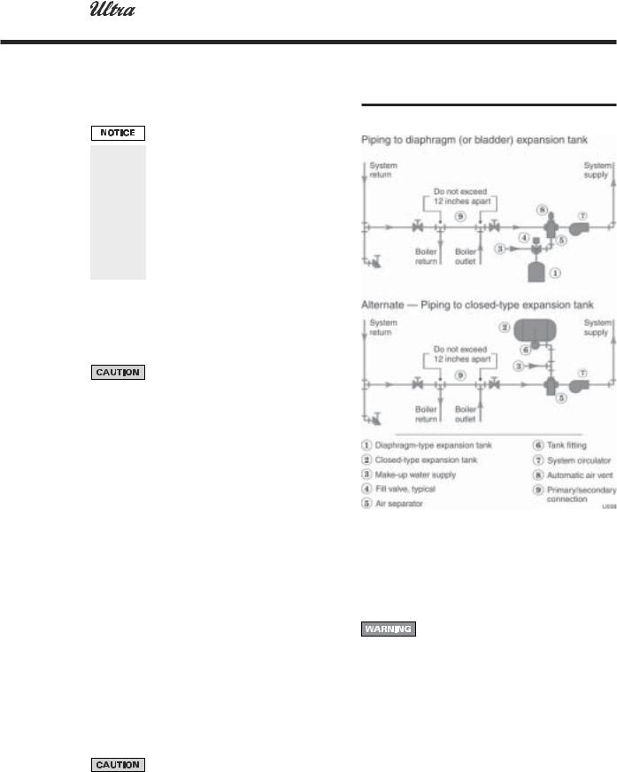
4.Most piping drawings in this manual show diaphragm expansion tanks. See Figure 4 for piping from air separator to expansion tank and make-up water line using a closed-type expansion tank.
5.Most chilled water systems are piped using a closedtype tank, as shown in Figure 10, page 18.
Diaphragm (or bladder) expansion tank
1.(Figure 4) Always install an automatic air vent on top of the air separator to remove residual air from the system.
Closed-type expansion tank
1.See Figure 4, Alternate, for piping connections when using a closed-type expansion tank.
2.Pitch any horizontal piping up towards tank 1 inch per 5 feet of piping. Connect to tank with at least ¾" piping to allow room for air to rise.
DO NOT install automatic air vents on closed-type expansion tank systems. Air must remain in the system and return to the tank to provide its air cushion. An automatic air vent would cause air to leave system, resulting in water-logging the expansion tank.
Figure 4 Expansion tank piping
Circulators
The boiler circulator (Taco 007 for Ultra-80 and -105; Taco 0011 for Ultra-155, -230, and -310) is shipped loose. Locate it either in the return or supply piping, as shown in the appropriate piping diagram in this manual.
DO NOT use the boiler circulator in any location other than the ones shown in this manual. The boiler circulator is selected to ensure adequate flow through the Ultra boiler. Failure to comply could result in unreliable performance and nuisance shutdowns from insufficient flow.
Sizing space heat system piping
1.See Figures 7 through 10, pages 15 – 18, for recommended piping. In all diagrams, the space heating system is isolated from the boiler loop by the primary/secondary connection.
2.Size the piping and components in the space heating system using recognized design methods.
Part number 550-101-233/0903 |
13 |

3 |
GAS-FIRED WATER BOILER — Boiler Manual |
|
Install water piping (continued)
Sizing DHW system piping
When using the boiler for dedicated DHW applications, use the circulator supplied with the boiler (007 for Ultra-80/105; 0011 for Ultra-155/230/310) to circulate to the water heater except where higher flow rates may be required for the heater used. Use the following method to select a circulator for the water heater on combined space heating/DHW systems.
1.Figure 5 shows recommended DHW piping, as shown in Figures 7 through 10, pages 15 – 18. All show direct connection of the DHW piping to the boiler because the boiler circulator shuts down during DHW operation.
2.Figure 6 shows the pump curves for suggested DHW
Figure 5 DHW piping (see Table 2 for approximate head losses)
circulators (Taco 007, 0011, 0012, 0013, 0014, B&G PL-36 or equivalent). Use these curves along with boiler pressure drop data from Table 2 to size the DHW piping and circulator. Or you can use Table 2 for a quick-selection method.
3.Table 2 uses the available head from the circulators listed to help you select the right circulator.
a.See Figure 5.
b.H1 is the head loss across the boiler.
c.H2 is the head loss across the DHW piping.
d.H3: Table 2 subtracts H1 and H2 from the available head of the circulator. This gives the maximum value for H3, head loss across the water heater.
4.Procedure to select a circulator using Table 2:
Step 1: From the water heater manufacturer’s data, find:
•Required boiler water flow rate, GPM, at 180°F.
•Pressure drop across the water heater at this flow rate, in feet water column.
Step 2: Find your boiler model in Table 2. Select a flow rate in column 1 just larger than the required flow rate from step 1.
Step 3: The value in column H3 must be larger than the water heater pressure drop from step 1.
Figure 6 Pump curves for typical circulators suggested for DHW loop
14
Table 2 Pipe sizing and head losses for DHW applications
(H1=boiler head loss; H2=piping head loss; H3=maximum allowable head loss through water heater based on available head of circulator chosen; i.e., Taco 007, 0011, 0012, 0013 or 0014, Bell or Gossett PL-36)
Part number 550-101-233/0903 |
 Loading...