


Gas-fired
Water boiler
Series 2
Control Supplement
Ultra-80, -105, -155, -230 & -310
NOTICE:
Series1/Series2identification
Read the boiler rating plate to determine the series number. The rating plate is located on the right side of the boiler.
•Wiring
•Operation
•Troubleshooting
with 


Instructions in this supplement are based on factory default parameter settings.
This document is a supplement to the Ultra Boiler Manual, and must only be used by a qualified heating installer/service technician. Read all instructions, including the Ultra Boiler Manual, before installing, starting or servicing the boiler. Perform all steps in the order given. Failure to comply could result in severe personal injury, death or substantial property damage.
Part number 550-100-029/0404

|
GAS-FIRED WATER BOILER SERIES 2 — Control Supplement |
|
Contents |
|
|
Please read before proceeding ............................................................. |
3 |
|
Hazard definitions ................................................................................. |
3 |
|
1 |
Field wiring ........................................................................................ |
4 |
2 |
Startup (Note 1) ................................................................................... |
6 |
3 |
Operating information ...................................................................... |
9 |
4 |
Troubleshooting .............................................................................. |
21 |
Note 1: See Ultra Boiler Manual for installation procedures and additional startup and operating information, and replacement parts.
2 |
Part number 550-100-029/0404 |


 GAS-FIRED WATER BOILER SERIES 2 — Control Supplement
Please read before proceeding
Installer— Read all instructions, including this manual, Ultra Boiler Manual, and the Ultra Vent Supplement, before installing. Perform steps in the order given.
User — This manual is for use only by a qualified heating installer/service technician. Refer to User’s Information Manual for your reference.
User — Have this boiler serviced/ inspected by a qualified service technician, at least annually.
Failure to comply with the above could result in severe personal injury, death or substantial property damage.
When calling or writing about the boiler— Please have the boiler model number from the boiler rating label and the CP number from the boiler jacket. You may list the CP number in the space provided on the Installation and service certificate found on page 27 of the Ultra Boiler Manual.
Consider piping and installation when determining boiler location.
Any claims for damage or shortage in shipment must be filed immediately against the transportation company by the consignee.
Failure to adhere to the guidelines on this page can result in severe personal injury, death or substantial property damage.
When servicing boiler —
•To avoid electric shock,disconnect electrical supply before performing maintenance.
•To avoid severe burns, allow boiler to cool before performing maintenance.
Commonwealth of Massachusetts
When the boiler is installed within the Commonwealth of Massachusetts:
•This product must be installed by a licensed plumber or gas fitter.
•If antifreeze is used, a reduced pressure back-flow preventer device shall be used.
Hazard definitions
The following defined terms are used throughout this manual to bring attention to the presence of hazards of various risk levels or to important information concerning the life of the product.
Indicates presence of hazards that will cause severe personal injury, death or substantial property damage.
Indicates presence of hazards that can cause severe personal injury, death or substantial property damage.
Indicates presence of hazards that will or can cause minor personal injury or property damage.
Indicates special instructions on installation, operation or maintenance that are important but not related to personal injury or property damage.
Part number 550-100-029/0404 |
3 |
1 |
GAS-FIRED WATER BOILER SERIES 2 — Control Supplement |
|
Field wiring
ELECTRICAL SHOCK HAZARD — For your safety, turn off electrical power supply at service entrance panel before making any electrical connections to avoid possible electric shock hazard. Failure to do so can cause severe personal injury or death.
Wiring must be N.E.C. Class 1. If original wiring as supplied with boiler must be replaced, use only type 105 °C wire or equivalent. Boiler must be electrically grounded as required by National Electrical Code ANSI/NFPA 70 – latest edition.
Install field wiring before venting to allow easier access to terminal strips.
Installation must comply with:
1.National Electrical Code and any other national, state, provincial or local codes or regulations.
2.In Canada, CSA C22.1 Canadian Electrical Code Part 1, and any local codes.
Line voltage connections
1.Connect 120 VAC power wiring to line voltage terminal strip in left compartment of electrical entrance, as shown in Figure 2, page 5, item 1.
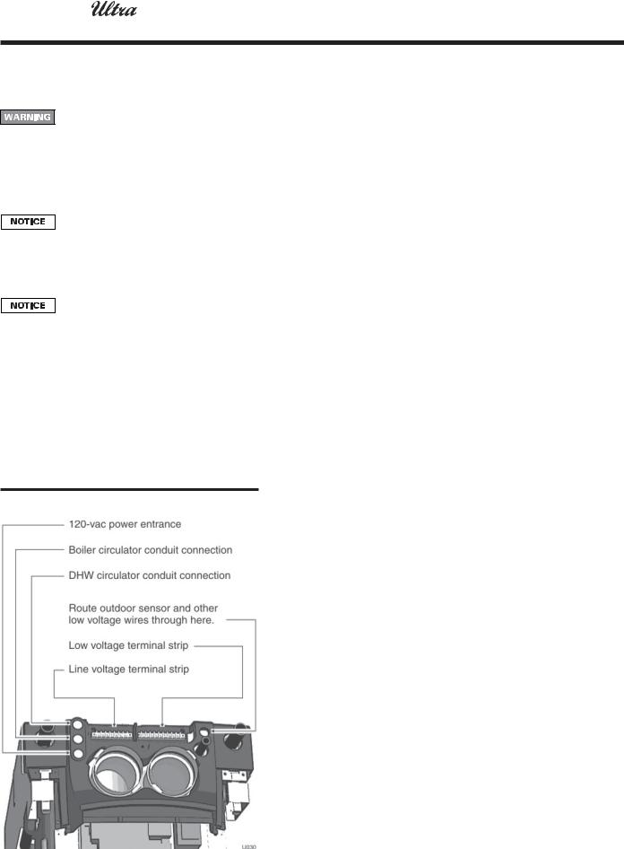
Figure 1 Routing field wiring
2.Provide and install a fused disconnect or service switch (15 amp. recommended) as required by the code. (See Figure 2, item 2)
3.Boiler circulator is shipped loose. Wire Boiler circulator as shown for Figure 2, item 3.
4.When connecting a DHW circulator, connect wiring to line voltage terminal strip as shown for Figure 2, item 5.
5.Route all wires and conduits to the jacket openings specified in Figure 1.
Wiring a system circulator
1.To activate a system circulator when the Boiler circulator operates, add a circulator relay and wire as shown in Figure 2.
2.You must install a relay as shown. DO NOT wire in parallel with the Boiler circulator. See CAUTION in Figure 2.
Low voltage connections
1.Connect low voltage wiring to low voltage terminal strip (Figure 3, page 5, item 1) as shown in Figure 3 and the boiler wiring diagram.
2.Route all low voltage wires through grommeted jacket opening to right of low voltage terminal strip, as shown in Figure 1.
Thermostat
1.Connect Figure 3, item 2, room thermostat or end switch (isolated contact only) between terminals 5 and 6.
2.Install thermostat on inside wall away from influences of drafts, hot or cold water pipes, lighting fixtures, television, sunrays, or fireplaces.
3.Thermostat anticipator (if applicable):
a.If connected directly to boiler, set for 0.1 amps.
b.If connected to relays or other devices, set to match total electrical power requirements of connected devices. See device manufacturers’ specifications and thermostat instructions for details.
Outdoor temperature sensor
1.Connect outdoor temperature sensor (Figure 3, item 6) between terminals 1 and 2 to enable outdoor reset operation of the Ultra boiler. If fixed-temperature operation is required, do not install outdoor sensor.
2.Mount sensor on exterior wall, shielded from direct sunlight or flow of heat or cooling from other sources.
3.If desired, install a summer/winter switch (Figure 3, item 7) across terminals 1 and 2. When the switch is closed, the boiler (space heating) circulator is disabled.
4.Route sensor wires through the hole at the right of the electrical entrance (see Figure 1).
DHW aquastat
1.Connect storage indirect water heater (DHW) aquastat (Figure 3, item 3) between terminals 3 and 4.
Additional limits
1.Connect additional limit controls and interlocks between the terminals shown in Figure 3.
2.Controls connected between terminals 6 and 7 (see Figure 3, item 4) will cause a soft lockout (automatic reset). When limit(s) closes, boiler will resume normal operation.
3.Controls connected between terminals 6 and 8 (see Figure 3, item 5) will cause a hard lockout (manual reset). The boiler will only restart after the Ultra display panel RESET switch is pressed.
4 |
Part number 550-100-029/0404 |

1 |
GAS-FIRED WATER BOILER SERIES 2 — Control Supplement |
|
|
|
|
|
|
Field wiring (continued) |
|
|
|
|
Figure 2 Line voltage field wiring connections (service switch provided by installer) |
Figure 3 Low voltage field wiring connections
Part number 550-100-029/0404 |
5 |

2 |
GAS-FIRED WATER BOILER SERIES 2 — Control Supplement |
|
Startup
Startup (continued from Ultra Boiler Manual)
1.Start the boiler only after completing all instructions in the Ultra Boiler Manual.
2.To start the boiler, follow the procedure given in Figure 4, page 7.
3.Once the boiler has started and is operating, continue the startup procedure by performing all of the following steps to set and verify operation of the Ultra controls.
Instructions in this supplement are based on factory default parameter settings.
Set space heating operation
Verify space heating mode
1.Press the “Mode” button until the display shows “Para.” This is the parameter mode.
2.Press the “Step” button until the display first digit shows “3.”
3.The last digit must show “1.” If any other number displays, press the “+” button until “1” shows in the right-hand digit. Press the“Store”button to save this setting.
4.See page 18 for further information.
Set space heating target temperature
1.Press the Ultra control panel “Step” button until the display first digit shows “4.” The right 3 digits show the outlet water temperature setting.
2.Press the “+” or “-” button to change the setting to the desired outlet water temperature. (The factory default setting is 190 °F.)
a.Outdoor sensor installed — Setting is the target temperature for outdoor temperature at or below (factory setting) 32 °F. At higher outside temperatures, the Ultra PhD control module calculates the target temperature. (See pages 9 and 10 for detailed discussion of outdoor reset.)
When a summer/winter switch is used, closing the switch will disable the boiler (space heating) circulator during summer operation.
b.Outdoor sensor not installed — Setting is the target temperature at all times.
3.Press the “Store” button to save the setting.
Check DHW operation setup
1.Go to step 2 if the control is in Parameter mode already. Press the “Mode” button until the display shows “Para” (parameter mode).
2.Press the “Step” button until the display first digit shows “2.”
3.The last digit must show “1.” If any other number displays, press the “+” button until “1” shows in the right-hand digit. Press the“Store” button to save this setting.
4.The Ultra PhD control module turns on the DHW circulator when the indirect water heater operating control closes. The control module shuts off the boiler circulator (stops space heating) during calls for DHW heating.
Verify operation — space heating
NOTE:“[ _ _ _ _ ]”in the following indicates the characters that should show on the Ultra display panel.“180” in the right 3 places means the display shows the measured boiler water temperature. The number shown will not necessarily be 180.
1.Turn down DHW aquastat on DHW tank (if used). If necessary, turn off power and remove one of the DHW aquastat wires to ensure boiler will not receive a DHW heat call.
2.Turn off power to boiler at service switch.
3.Wait a few seconds, then turn on power to boiler.
[A180] (self-check on power-up, for a few seconds) [0180] (no call for heat)
4.Raise room thermostat to call for heat.
[5180] (blower/circulator on) The blower and boiler circulator energize and the control checks for air flow.
[1180] (prepurge) Blower speed will increase to ignition speed. The blower will run in prepurge for 10 seconds.
[2180] (ignition) After prepurge, the control module opens the gas valve and starts ignition spark.
a.If burner flame proves within 4.5 seconds, burner continues to fire. Burner will fire at startup rate
— 50% of maximum input — for about 10 seconds to allow flame to stabilize.
b.If burner flame does not prove within 4.5 seconds, control module attempts ignition sequence again. Flame must prove within 5 attempts or control will lockout (display will show [E 02]).
c.Verify flame failure operation by closing boiler manual gas cock to prevent gas flow. Open manual
gas valve after testing.
[3180] (burner on, space heating) Once flame is proven and stable, the burner turns down to low fire for approximately 2 minutes.
•After this low fire period, the burner is allowed to modulate. Firing rate depends on actual outlet water temperature versus target temperature.
6 |
Part number 550-100-029/0404 |
2 |
GAS-FIRED WATER BOILER SERIES 2 — Control Supplement |
|
Startup (continued)
Figure 4 Operating Instructions (Read page 7 and the Ultra Boiler Manual before proceeding.)
FOR YOUR SAFETY READ BEFORE OPERATING
If you do not follow these instructions exactly, a fire or explosion may result causing property damage, personal injury or loss of life.
A.This appliance does not have a pilot. It is equipped with an ignition device which automatically lights the burner. Do not try to light the burner by hand.
B.Before OPERATING, smell all around the appliance area for gas. Be sure to smell next to the floor because some gas is heavier than air and will settle on the floor. See below.
C.Use only your hand to turn the gas control knob. Never use tools. If the knob will not turn by hand, don't try to repair it; call a qualified service technician. Force or attempted repair may result in a fire or explosion.
D.Do not use this appliance if any part has been under water.
Immediately call a qualified service technician to inspect the appliance and to replace any part of the control system and any gas control, which has been under water.
WHAT TO DO IF YOU SMELL GAS
•Do not try to light any appliance.
•Do not touch any electric switch; do not use any phone in your building.
•Immediately call your gas supplier from a neighbor's phone. Follow the gas supplier's instructions.
•If you cannot reach your gas supplier,call the fire department.
OPERATING INSTRUCTIONS
1.Stop! Read the safety information above. This appliance is equipped with an ignition device which automatically lights the burner. Do not try to light the burner by hand.
2.Set room thermostat(s) to lowest setting. Verify external manual gas valve is open (valve handle parallel to gas piping).
3.Turn OFF POWER switch on the Ultra control panel.
4.Rotate two thumb screws at bottom of access door counterclockwise to release door.
5.Remove boiler access door.
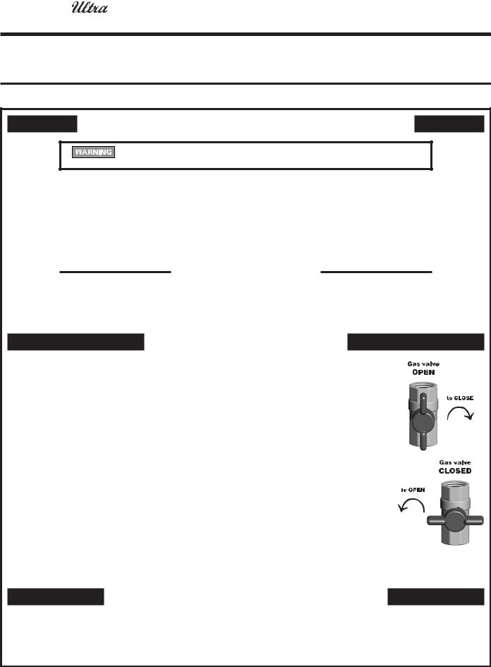
6.Turn boiler manual gas valve knob counterclockwise to open gas supply.
7.Smell for gas in the boiler enclosure. If you smell gas, STOP! Follow "B" in the safety information above. If you don't smell gas, go to the next step.
8.Turn ON POWER switch on the Ultra control panel.
9.Set thermostat(s) to desired setting.
10.The Ultra control panel display left digit will show a sequence of numbers (0, 1, 2, etc.) that indicate boiler control sequence. Digit 3 or 4 indicates boiler is firing. Digit 0 means there is no call for heat (all room thermostats and domestic water heater satisfied).
11.If the appliance will not operate when there is a call for heat and piping is not hot, follow the instructions "To Turn Off Gas To Appliance" below and call your service technician or gas supplier.
12.Replace jacket front panel. Make sure panel is seated firmly in place and all joints are visually sealed. Then tighten the two thumb screws at bottom of access door firmly.
Boiler manual gas valve
TO TURN OFF GAS TO THE APPLIANCE
1.Set room thermostats to lowest setting.
2.Turn off all electric power to the boiler if service is to be performed. Turn OFF POWER switch on the Ultra control panel.
3.Close external manual gas cock (valve handle perpendicular to gas piping). Remove boiler access door. Turn boiler manual gas valve knob clockwise to close gas supply.
4.Replace boiler access door.
Part number 550-100-029/0404 |
7 |
2 |
GAS-FIRED WATER BOILER SERIES 2 — Control Supplement |
|
Startup (continued)
Verify operation — space heating
(continued from previous page)
5.Allow boiler to bring water temperature to target temperature.
[6180] (target temperature reached) The burner will shut down. The blower will run in postpurge (see below), then turn off. The boiler circulator continues to run as long as there is a call for heat.
6.Lower room thermostat to stop call for heat.
[1180] (postpurge) When the room thermostat is satisfied (call for heat ended), the burner turns off. The blower will continue for a 15-second postpurge, then turn off. (If another call for heat occurs, the boiler will remain off for one minute before starting again, and the display will show [6180].)
[0180] (no call for heat) Boiler is now in standby mode (waiting for heat call).
7.Repeat above steps several times to verify operation.
8.Return the room thermostat to normal setting.
Verify operation — DHW
1.Reconnect DHW aquastat wiring to boiler if necessary.
2.Turn off power to boiler at service switch.
3.Wait a few seconds, then turn on power to boiler.
[A180] (self-check on power-up, for a few seconds) [0180] (no call for heat)
4.Raise DHW aquastat above tank temperature, to call for heat.
[5180] (blower/circulator on) The blower and DHW circulator energize and the control checks for air flow.
[1180] (prepurge) Blower speed will increase to ignition speed. The blower will run in prepurge for 10 seconds.
[2180] (ignition) After prepurge, the control module opens the gas valve and starts ignition spark.
a.If burner flame proves within 4.5 seconds, burner continues to fire. Burner will fire at startup rate
— 50% of maximum input — for about 10 seconds to allow flame to stabilize.
b.If burner flame does not prove within 4.5 seconds, control module attempts ignition sequence again. Flame must prove within 5 attempts or control will lockout (display will show [E 02]).
c.Verify flame failure operation by closing boiler manual gas valve to prevent gas flow. Open gas cock after testing.
[4180] (burner on, DHW) Once flame is proven and stable, the burner is allowed to modulate. Firing rate depends on actual outlet water temperature versus target temperature.
5.Allow boiler to bring water temperature to target temperature.
[6180] (target temperature reached) The burner will shut down. The blower will run in postpurge (see below), then turn off. The DHW circulator continues to run as long as there is a call for DHW heating.
6.Lower DHW aquastat to stop call for heat.
[1180] (postpurge) When the room thermostat is satisfied (call for heat ended), the burner turns off. The blower will continue for a 15-second postpurge, then turn off. (If another DHW call for heat occurs, the boiler will begin the heating cycle immediately.)
[8180] (DHW circulator run-on) The DHW circulator continues to run for 30 seconds.
[0180] (no call for heat) Boiler is now in standby mode (waiting for heat call).
7.Repeat above steps several times to verify operation.
8.Return the DHW aquastat to normal setting.
Operating information
1.To check operating conditions (actual and target temperatures, for example), see page 15 for an explanation of the Ultra control module Information mode.
2.During normal operation (no shutdown or lockout), the right 3 display digits show actual boiler outlet water temperature.
Perform Check-out procedures
1.Perform all steps of the Check-out/startup verification listed in the Ultra Boiler Manual.
Replace boiler jacket front door
Replace boiler jacket front door after servicing. The boiler front door must be securely fastened to the boiler to prevent boiler from drawing air from inside the boiler room. This is particularly important if the boiler is located in the same room as other appliances. Failure to keep the door securely fastened could result in severe personal injury or death.
8 |
Part number 550-100-029/0404 |
3 |
GAS-FIRED WATER BOILER SERIES 2 — Control Supplement |
|
Operating information
Ultra  Control Module
The Ultra boiler is controlled by a microprocessor electronic control — the Ultra Control Module. The module senses outlet water temperature, return water temperature, flue temperature and outdoor temperature (when outdoor sensor is installed). It uses this information (plus input from external limit and operating controls) to regulate boiler on/off operation and can modulate boiler firing rate to more closely match output to demand.
Electrical specifications
Ultra boilers require 120 VAC/60 HZ power supply and are not polarity sensitive.
Control module specifications |
|
|
• |
Supply voltage |
120 vac / 60 hz |
• |
Electrical demand |
10 va |
• |
Prepurge timing |
10 seconds |
• |
Postpurge timing |
15 seconds |
• Min. off time, space heating |
1 minute |
|
• Pump run on after space htg. |
10 seconds |
|
• Min. off time, DHW |
0 seconds |
|
• Pump run on after DHW |
30 seconds |
|
• Line voltage fuse, F1 |
5 amp fast-blow |
|
• Low voltage fuse, F3 |
4 amp slow-blow |
|
Boiler temperature regulation
Operating temperature (target)
The Ultra control module senses outlet water temperature and regulates boiler firing rate to achieve a target temperature, set by installer, by setting Parameter 4. Temperature can be set between 70°F and 190°F. See page 18 for procedure.
•Space heating — Target temperature is fixed (equal to Parameter 4) when outdoor reset is not installed.
•Space heating — Target temperature is calculated as described under “Outdoor reset operation” when outdoor sensor is connected. Exception: See explanation of “Supply temperature boost.”
•DHW heating — Target temperature is 50°F + Parameter 1. Do not change parameter 1 from the factory default setting of 140°F unless the application is specially engineered for other temperature.
High limit operation
If outlet water temperature exceeds target temperature (or 190°F, whichever is lower), high limit action occurs. The control module shuts the burner off.
DHW operation (if used)
The boiler is factory set to immediately change target outlet water temperature to 190°F on a call for heat from the DHW aquastat.
Additional Thermal Overrun Protection
High limit operation shuts down the burner when the outlet water temperature exceeds the target temperature. However, adverse conditions could cause the water temperature to rise too quickly, overshooting this temperature.The Ultra control module’s technology provides advanced protection in the event of thermal overrun. Using its electronics, the Ultra control module provides two additional levels of overrun protection:
Level 1 Indication would occur if supply or return water temperature reached 203°F. The Ultra control module would display a soft lockout code (“b” followed by “18” if on the supply, or “19” if on the return). The module would not operate the burner again until the water temperature dropped 9°F below target temperature.
Level 2 Lockout would occur if supply or return water temperature reached 210°F. The Ultra module would enter hard lockout and display an error code (“E” followed by “18” if on the supply or “19” if on the return). NOTE: Hard lockout requires manually pressing the Ultra display panel reset button to restart operation. Service
technician must troubleshoot the cause of the problem and correct it before placing the boiler back in operation.
Low water protection
1.The control module uses temperatures sensed at both supply and return areas of the heat exchanger. If the flow rate is too low (temperature difference too high) or either temperature is too high, the control module shuts the boiler down. This ensures boiler shutdown in the event of low water or low flow conditions.
2.Some codes and jurisdiction may accept these integral features of the control in lieu of requiring an additional limit control or low water cutoff. Consult local jurisdiction to determine.
Outdoor reset operation, if used
Target temperature with outdoor reset
All Ultra boilers are shipped with an outdoor temperature sensor.When this sensor is installed (low voltage terminal strip terminals 1 and 2), the control module regulates target outlet water temperature based on outside temperature.
Set the temperature curve by setting Parameter 4 to:
•ODT (outdoor design temperature for the area).
•For ODT of 32°F or lower:
•Set Parameter 4 to the desired supply temperature at the ODT.
Part number 550-100-029/0404 |
9 |
 Loading...