


EGHGas-Fired Boiler
Control Supplement
EGH-105 to EGH-125 Series 4 Natural gas‡
CSD-1 control system
‡For propane boilers, install EGH propane conversion kit in addition to following the instructions in this Control Supplement.
Part No. 550-110-677/0299
EGH-105 to EGH-125 Control Supplement
Hazard definitions
To the installer:
Please read this page first
The following terms are used throughout this Control Supplement to bring attention to the presence of hazards of various risk levels or to important information concerning the life of the product.
Indicates presence of hazards that will cause severe personal injury, death or substantial property damage.
Indicates presence of hazards that can cause severe personal injury, death or substantial property damage.
Indicates presence of hazards that will or can cause minor personal injury or property damage.
Indicates special instructions on installation, operation or maintenance that are important but not related to personal injury or property damage.
This Control Supplement must only be used by a qualified installer/service technician. Read these instructions completely before beginning the installation. Failure to follow these instructions can cause severe personal injury, death or substantial property damage.
This Control Supplement is for CSD-1 controls on EGH-105 to EGH-125 boilers only, specifically for:
•Water boilers without tankless heater. (CSD-1 is not available for water boilers with tankless heater.)
•Steam boilers with or without tankless heater.
This document is only intended as a supplement to the EG, PEG and EGH (Series 4) Boiler Manual (referred to in this Supplement as the EGH Manual). Follow all instructions in the EGH Manual in addition to the instructions in this Control Supplement.
The installation must conform to the requirements of the authority having jurisdiction, or, in the absence of such requirements, to the National Fuel Gas Code,ANSI Z-223.1/NFPA-54 (latest edition).Where required by the authority having jurisdiction the installation must conform to the American Society of Mechanical Engineers (ASME) Safety Code for Controls and Safety Devices for Automatically-Fired Boilers, Number CSD-1.
Contents I. ................. |
Installation .......................................................................... |
4 |
II. ................ |
Piping connections ............................................................. |
6 |
III. ............... |
Install boiler controls ......................................................... |
6 |
IV. ............... |
Optional heaters ................................................................ |
7 |
V. ................ |
Gas piping ........................................................................... |
8 |
VI. .............. |
Wiring .................................................................................. |
8 |
VII. ............. |
Final adjustments ............................................................. |
22 |
VIII. ............ |
Check-out procedure ....................................................... |
24 |
IX. .............. |
Service and maintenance ................................................ |
31 |
X. ............... |
Replacement parts ........................................................... |
32 |
2 |
|
Part Number 550-110-677/0299 |

CSD-1 control system — Natural gas
Carton guide
Table 1 Boiler cartons
Verify that the correct cartons are available before beginning assembly. Note that the Base assembly and Trim & controls cartons for CSD-1 are special. The CSD-1 ignition control panel (in Base assembly carton) consists of ignition control module, impulse relay and lighted push-button switch mounted and wired on a panel base.
Carton |
|
Comments |
EGH-105 |
EGH-115 |
|
EGH-125 |
|||
|
|
|
|
|
|
|
|
|
|
Section assembly (a) |
|
With tankless opening |
321-711-120 |
321-711-130 |
|
321-711-140 |
|||
|
|
|
|
|
|
|
|
||
|
Without tankless opening |
321-711-125 |
321-711-135 |
|
321-711-145 |
||||
|
|
|
|||||||
|
|
|
|
|
|
|
|
|
|
Base assembly (b) |
|
CSD-1 |
|
381-700-400 |
381-700-402 |
|
381-700-404 |
||
|
|
|
|
|
|
|
|
|
|
Base panels |
|
|
|
381-700-250 |
381-700-255 |
|
381-700-260 |
||
|
|
|
|
|
|
|
|
|
|
Jacket |
|
|
|
411-800-280 |
411-800-290 |
|
411-800-300 |
||
|
|
|
|
|
|
|
|
|
|
Collector hood |
|
|
|
450-014-752 |
450-014-753 |
|
450-014-754 |
||
|
|
|
|
|
|
|
|
|
|
Draft hood |
|
|
|
450-206-242 |
450-206-243 |
|
450-206-244 |
||
|
|
|
|
|
|
|
|
|
|
Float low water cutoff (steam) |
|
Gravity return (M&M #67W-1) |
381-700-341 |
381-700-341 |
|
381-700-341 |
|||
|
|
|
|
|
|
|
|
||
|
Pumped return (M&M #42-A) |
511-114-531 |
511-114-531 |
|
511-114-531 |
||||
|
|
|
|||||||
|
|
|
|
|
|
|
|
|
|
Vent damper (optional) (c) |
|
|
|
381-800-446 |
381-800-447 |
|
381-800-447 |
||
|
|
|
|
|
|
|
|
|
|
Tankless heater (optional) |
|
Steam boilers only |
386-700-350 |
386-700-350 |
|
386-700-350 |
|||
|
|
|
|
|
|
|
|
|
|
|
|
Water, CSD-1 — or — |
381-700-406 |
381-700-406 |
|
381-700-406 |
|||
Trim & controls (see below) |
|
Steam, CSD-1, gravity return — or — |
381-700-408 |
381-700-408 |
|
381-700-408 |
|||
|
|
||||||||
|
|
|
|
|
|
|
|
|
|
|
|
Steam, CSD-1, pumped return |
381-700-410 |
381-700-410 |
|
381-700-410 |
|||
|
|
|
|
|
|
|
|
||
Note a — CSD-1 water boilers cannot be equipped with a tankless heater. |
|
|
|
|
|
||||
Note b — Base assembly includes burner tubes, gas train components, pilot assembly and control panel (with ignition control). |
|
||||||||
Note c — EGH vent dampers meet ASME CSD-1 requirements (paragraph CF-210(c)) because they comply with ANSI Z21.13. |
|
||||||||
|
|
|
|
|
|
|
|
|
|
|
|
|
|
|
|
|
|
|
|
Steam trim and control carton |
|
Steam trim and control carton |
Water trim carton |
|
|||||
Gravity return |
|
Pumped return |
|
|
|
|
|
||
|
|
|
|
|
|
|
|
||
Pressure limit control, automatic reset |
Pressure limit control, automatic reset |
Aquastat, automatic reset |
|
||||||
|
|
|
|
|
|
|
|
|
|
Pressure limit control, manual reset |
|
Pressure limit control, manual reset |
Aquastat, manual reset |
|
|||||
|
|
|
|
|
|
|
|||
Probe low water cutoff, manual reset |
Probe low water cutoff, manual reset |
Probe low water cutoff, manual reset |
|||||||
|
|
|
|
|
|
|
|
|
|
Transformer/relay |
|
Transformer/relay |
|
Transformer/relay |
|
||||
|
|
|
|
|
|
|
|
|
|
Wire harness, steam gravity return |
|
Wire harness, steam pumped return |
Wire harness, water |
|
|||||
|
|
|
|
|
|
|
|
||
Crimp spade wire terminations |
|
Crimp spade wire terminations |
|
Crimp spade wire terminations |
|||||
|
|
|
|
|
|
|
|
|
|
ASME Relief valve |
|
ASME Relief valve |
|
ASME Relief valve |
|
||||
|
|
|
|
|
|
|
|
|
|
Pressure gauge |
|
Pressure gauge |
|
|
|
|
|
||
|
|
|
|
|
|
|
|
|
|
Gauge glass and valves |
|
Gauge glass and valves |
|
|
|
|
|
||
|
|
|
|
|
Pressure/temperature gauge |
||||
Brass cross, brass nipple, bushings (3) and |
Brass cross, brass nipple, bushings (3) |
||||||||
|
|
|
|
||||||
siphons (3) for mounting pressure controls |
and siphons (3) for mounting pressure |
|
|
|
|
||||
and gauge |
|
controls and gauge |
|
|
|
|
|
||
|
|
|
|
|
|
|
|
|
|
Part Number 550-110-677/0299 |
|
|
|
|
|
|
3 |
||
EGH-105 to EGH-125 Control Supplement
I
Place the boiler
Install gas train
Install vent/breeching
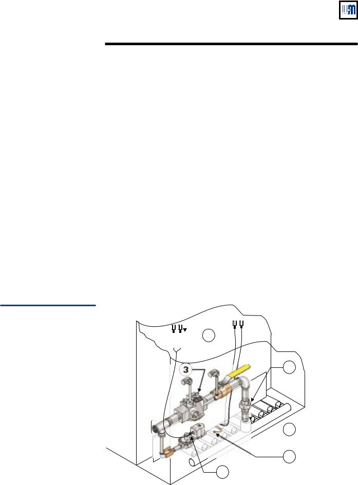
Figure 1
Gas train assembly
Installation
Refer to the EGH Manual. Read Section I and follow all of its guidelines. Complete the following steps of Section I of the EGH Manual:
•Placing the boiler
•Installation of optional water heaters, steam boilers only (including pages 13–14)
•Hydrostatic pressure test
•Installation of flue collector hood
•Installation of (burner) drawer assembly and front access panel and back base channel
•Jacket installation
•Draft hood installation
Connect gas train assembly to burner manifold:
•Apply pipe dope to 1" nipple for insertion into burner manifold coupling (Figure 1, item 1). Insert and tighten nipple.
•Pipe lower half of ground joint union to the 1” nipple (Figure 1, item 2).
•Knock out the jacket gas valve opening on the desired side of the boiler (may be routed through either right or left side).
•Place gas train in position (either routed to the left, as shown, or to the right) and tighten the ground joint union loosely. Position the gas train assembly and tighten the union.
•Connect vent lines (routed to outside per code requirements) to ¼" tubing vent connections on main gas valve and pilot gas pressure regulator (Figure 3, item 3).
•Connect pilot gas tubing (1/8" aluminum) to adapter in pilot gas valve outlet (Figure 1, item 4).
•Crimp connect two ¼" spade terminals (provided) to ends of pilot gas valve wires (Figure 1, item 5).
Install vent system and breeching per EGH Manual Section I. If optional vent damper is used, install vent damper (using Section I of this Supplement) before installing breeching.


 5
5
2
 1
1
4
3
677-09
4 |
Part Number 550-110-677/0299 |
CSD-1 control system — Natural gas
Install optional vent damper (if supplied)
If not installing a vent damper, proceed to next section (Piping connections).
Once a vent damper has been operated on an EGH boiler,the boiler will no longer operate without a damper installed.
Only dampers listed in the Replacement parts list in this Supplement are certified for use with EGH Series 4 boilers. Any other damper installed could cause severe personal injury or death.
Minimum clearances — Provide a minimum of 6" between the damper and any combustible material. (Provide a minimum of 46" between EGH jacket top and a combustible ceiling.)
Damper must be installed directly on top of draft hood so that it serves only that boiler. DO NOT modify draft hood or damper, or make another connection between draft hood and damper or boiler. This will void AGA/CGA certification and will not be covered by Weil-McLain warranty. Any changes will cause severe personal injury, death or substantial property damage.
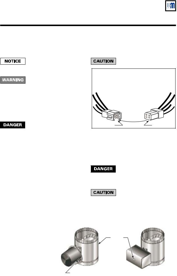
Install damper directly on top of draft hood, with arrow pointing straight up. Install so the damper blade indicator is visible to the user. See Figure 2.
Screws or rivets used to secure the damper to the vent pipe and the draft hood must not interfere with rotation of the damper blade.
Install damper harness between damper actuator and knockout in right top of boiler jacket. Knock out opening in jacket top and install strain relief bushings in jacket
and actuator wiring openings. Insert wires and secure strain relief clamps. See Figure 6, 8, or 10 as applies.
Keep wiring harnesses clear of all hot surfaces.
WARNING
LINE UP KEYWAY WHEN
CONNECTING PLUGS.
FORCING A MISMATCH
CAN CAUSE A
HAZARDOUS CONDITION.
Keyway |
Key |
677-10 |
Read and apply the harness plug warning label (above) so that it is visible after installation.
Remove dummy plug from damper connector in boiler wiring harness. Plug damper harness receptacle into damper harness plug. See Figure 6, 8, or 10 as applies.
By-passing (jumpering) damper will cause flue products such as carbon monoxide to escape into the house. This will cause severe personal injury or death.
After boiler has operated once, if either end of harness is disconnected, the system will shut down. The boiler will not operate until the harness is reconnected.
|
|
Effikal damper |
Johnson Controls damper |
|
Figure 2 |
||||
|
|
|||
Vent damper assemblies |
|
Damper |
||
|
|
|
blade |
|
|
|
|
indicator |
|
Hold-open switch (Effikal only) — |
|
Install damper so that switch is |
|
visible and accessible to user. |
677-05 |
Part Number 550-110-677/0299 |
5 |
EGH-105 to EGH-125 Control Supplement
II Piping connections
Connect steam (water) piping to the boiler per EGH Manual Section II.
Water boilers — make provision for mounting probe low water cutoff in the supply or return piping, above the top of the boiler. The low water cutoff must be between the boiler and any isolation valve(s).
III Install boiler controls — water boilers
|
|
|
|
The controls may be mounted on either end of the boiler. Mount all controls |
||
|
|
|
|
on the same end. The junction box (electrical entrance) must also be mounted |
||
|
|
|
|
on the same end as the controls. |
|
|
|
|
|
|
Install the probe low water cutoff in the supply or return piping, above the |
||
|
|
|
|
top of the boiler. The low water cutoff must be mounted between the boiler |
||
|
|
|
|
and any isolation valve(s) installed in the piping. |
|
|
|
|
|
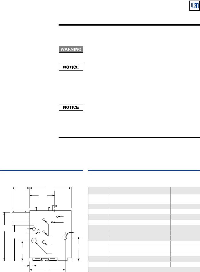
Install water trim components as required by ASME CSD-1, latest edition. See Figure 3 and |
|||
|
|
|
Table 2 for controls required and tapping usage. See Figure 6 for finished assembly. |
|||
|
|
|
Plug all unused tappings. |
|
|
|
|
|
|
All piping and control connections must also comply with the EGH Manual. |
|||
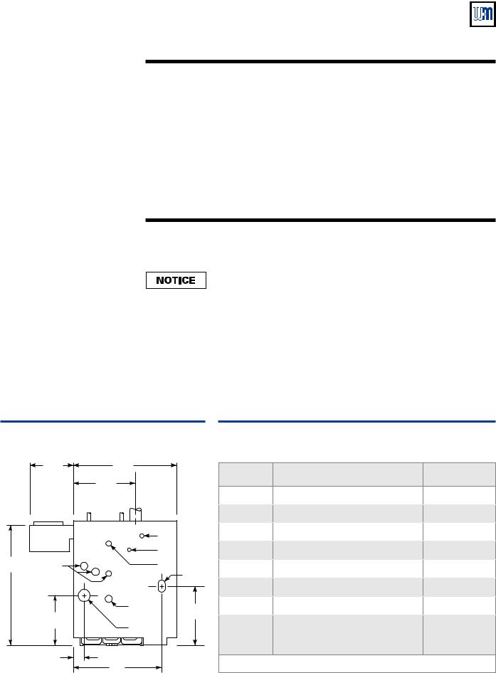
Figure 3 |
|
|
|
Table 2 |
|
|
Water boiler connections |
|
|
Water boiler connections |
|
||
|
11¾" |
275/8" |
|
Tapping |
Application |
W-M Part No. |
|
163/16" |
|
||||
|
|
|
|
|
||
|
|
|
|
D |
Boiler drain connection |
— |
|
E |
G |
Supply |
E |
ASME relief valve (per EGH manual) |
— |
|
|
|
L |
G |
Pipe to air vent or compression tank |
— |
|
|
|
|
|
|
|
|
|
|
S |
H |
Honeywell L4006E-1000 M/R limit |
510-312-041 |
32¾" |
Not |
|
H |
L |
Pressure/temperature gauge |
510-218-097 |
used |
|
|||||
|
|
|
||||
|
|
|
|
V |
|
|
|
|
|
|
S |
Temperature limit control, auto reset |
510-312-209 |
|
|
D |
|
V |
Gas supply connection (right or left) |
— |
|
13½" |
|
|
165/8" |
|
|
|
Return |
|
McDonnell & Miller PS852M-24 M/R |
|
||
|
|
|
|
|||
|
|
Not shown |
probe LWCO (Mount in supply or |
511-114-530 |
||
|
|
|
|
|||
|
|
|
|
|
return piping, above top of boiler) |
|
211/16" |
24" |
|
|
Plug all tappings not used. |
|
|
|
|
|
|
|
||
|
|
|
677-08 |
|
|
|
6 |
Part Number 550-110-677/0299 |
CSD-1 control system — Natural gas
III Install boiler controls — steam boilers
All water level controls must mount on the left end of the boiler. Failure to do so could result in nuisance shutdowns and possible lockout on the manual reset control due to water level variations from end to end. Substantial property damage could result from freezing due to loss of heat.
All controls must mount on left end of the boiler. The correct tappings are available only on the left end section.
Install steam trim components as required by CSD-1, latest edition. See Figure 4 and Table 3.
See also Figure 8 or Figure 10 for finished assembly.
•CSD-1 requires two low water cutoffs (one manual reset) and two limit controls (one manual reset) as shown in the illustration.
•For float type (automatic reset only) low water cutoffs other than those shown in this Supplement, refer to EGH Manual for mounting and piping instructions.
|
|
|
|
|
Install a blowdown valve on any float type low water cutoff as described in |
||
|
|
|
|
|
the EGH Manual, Section III. |
|
|
|
|
|
Plug all unused tappings. |
|
|
||
|
|
|
All piping and control connections must also comply with the EGH Manual. |
||||
|
IV Optional heaters — steam boilers only |
||||||
|
|
|
Install optional tankless heater, if used, (steam boiler only) per EGH Manual Section IV. |
||||
Figure 4 |
|
|
|
|
Table 3 |
|
|
Steam boiler connections |
|
|
Steam boiler connections |
|
|||
11¾" |
275/8" |
|
Tapping |
Application |
W-M Part No. |
||
|
|
|
|
|
|||
|
163/16" |
|
|
T |
McDonnell & Miller PS852M-24 M/R |
511-114-530 |
|
|
|
|
|
|
|||
|
|
|
|
|
probe LWCO |
||
|
|
|
|
|
|
|
|
|
E |
G |
Supply |
|
C |
Not used — plug tapping |
— |
|
risers |
|
D |
Drain connection (per EGH manual) |
— |
||
|
|
|
|
|
|||
|
|
|
L |
|
E |
ASME relief valve (per EGH manual) |
— |
|
|
|
S |
|
G |
Not used - plug tapping |
— |
32¾" |
C |
|
|
|
H |
Float LWCO, automatic reset — |
— |
2313/16 " |
T |
|
H |
V |
Gravity return — McD-M 67W-1 |
511-114-494 |
|
(Water line) |
|
|
|
|
Pumped return — McD-M 42-A |
511-114-531 |
|
|
|
|
|
|
|
||
|
|
|
D |
|
|
Pressure gauge |
510-218-045 |
|
|
|
165/8" |
L |
Pressure limit, automatic reset |
510-312-135 |
|
13½" |
|
|
|||||
|
Return |
|
|
Honeywell L404C-1147 M/R limit |
510-312-060 |
||
|
|
|
|
|
|||
|
|
|
|
|
S |
Skim tapping (per EGH manual) |
510-312-209 |
211/16" |
|
|
|
|
V |
Gas supply connection (right or left) |
— |
|
24" |
|
|
|
Plug all tappings not used. |
|
|
|
|
|
677-07 |
|
|
||
Part Number 550-110-677/0299 |
|
|
|
|
|
7 |
|
EGH-105 to EGH-125 Control Supplement
V Gas piping
Size and connect gas supply piping per EGH Manual, Section V.
The gas supply can enter from either the right or left side of the jacket. Be sure the gas train is directed to the correct side.
Support gas line securely. Do not support weight of gas line off of boiler gas train.
Purge air from gas piping and perform gas line and gas connection leak test per Section V of the EGH Manual.
VI Wiring
For your safety, turn off electrical power supply before making any electrical connections to avoid possible shock hazard.
A strain relief bushing and adapter must be used at each point where wiring passes through the boiler jacket or control cases to protect wiring insulation.
Assembly illustrations and wiring diagrams
This Supplement contains three wiring diagrams and associated assembly illustrations. Refer to the following, as applicable:
•Water boilers —Figures 5 and 6
•Steam boilers, gravity return — Figures 7 and 8
•Steam boilers, pumped return — Figures 9 and 10
General
Refer to EGH Manual, Section VI for further information.
All wiring must be installed in accordance with the requirements of the National Electrical Code and any additional national, state or local code requirements having jurisdiction. All line voltage wiring external to boiler jacket must be N.E.C. class 1.
Provide a separate electrical circuit with a fused disconnect switch (15 amp recommended) to supply the boiler. Wiring to the boiler must be No. 14 gauge or heavier, installed in conduit.
The boiler must be electrically grounded in accordance with the National Electrical Code, ANSI/NFPA No. 70, latest edition.
Use 105 °C thermoplastic wire, or equivalent, if any original wire must be replaced (except for pilot spark and sense wires).
Wiring procedure
1.Mount all controls as directed in Section III of this Supplement. Refer to the assembly illustration for the type of boiler installed (Figure 6, 8 or 10).
2.Mount the junction box supplied with the boiler on the inside left (or right) side of the jacket as shown in the assembly illustration (using screws and nuts provided). Mount the junction box on the same end of the boiler as the controls will be mounted.
3.Attach the transformer/relay to the junction box.
4.Mount the CSD-1 control panel on the jacket interior panel as shown in the appropriate assembly illustration (Figure 6, 8 or 10), using screws and nuts provided.
5.Crimp connect Z\v" spade terminals (provided) to the pilot gas valve wires if not already done in Section I of this Supplement.
6.If optional vent damper is installed, make sure damper harness has been routed through a strain relief bushing in the jacket and damper actuator as directed in Section I of this Supplement. Secure damper harness conduit to top of jacket with clamps provided.
7.The main gas valve wires are pre-attached to the CSD-1 control panel. The spark and sense wires from the pilot are factory installed to the pilot.
Connect these wires as shown in the wiring diagram.
8.Use the wiring harness provided with the boiler to complete wiring of the remaining components according to the appropriate wiring diagram and assembly illustration.
8 |
Part Number 550-110-677/0299 |
CSD-1 control system — Natural gas
VI Wiring — sequence of operation
General
The following sequence of operation applies to all wiring diagrams in this Supplement — both water and steam.
Call for heat
On a call for heat (from thermostat or operating control):
1.Limit control and water level control contacts are assumed closed.
2.Vent damper (if provided) will open.
3.Ignition control checks for signal at pilot. (No signal should be present.)
If no signal is sensed (normal condition):
a.Pilot solenoid opens.
b.Pilot ignition spark begins.
c.Pilot ignites.
d.Pilot proves.
If a signal is sensed (abnormal condition) by the ignition control, the control will lockout.
On failure to establish pilot flame signal within 15 seconds, the ignition control will turn off the pilot gas valve. It will wait 5 minutes, then retry for ignition. If the second ignition attempt fails, the ignition control will lockout and illuminate the red lockout light.
This will activate the alarm contact of the impulse relay, providing an isolated contact closure across terminals A1 and A2 of the CSD-1 control panel terminal strip. The contact rating is 15 amps at 250VAC.
To reset the boiler, push the red reset button on the CSD-1 control panel.
4.Once pilot is proved the ignition control activates main gas valve. Main burners will ignite and boiler will continue to fire until terminated by limit action or no call for heat.
Lockout modes
In addition to lockout on flame-sense failure, the boiler may also experience lockout due to shutdown of a manual reset control.
The boiler is equipped with a manual reset limit control and a manual reset low water cutoff. Should the limit control lockout, it can only be reset by pressing the reset button on the control. The manual reset probe low water cutoff can be reset after lockout by pressing the reset button on the control or by interrupting power momentarily.
Steam boilers — Do not substitute another manual reset low water cutoff for the one specified and supplied with the boiler. Other controls may not operate as intended and could cause serious operating problems or failures.
Troubleshooting
Refer to Section VIII, Check-out procedure — troubleshooting, of this Supplement and to component manufacturer’s literature supplied in the boiler manual envelope for further information on operating conditions.
Part Number 550-110-677/0299 |
9 |
10
677/0299-110-550 Number Part
VI |
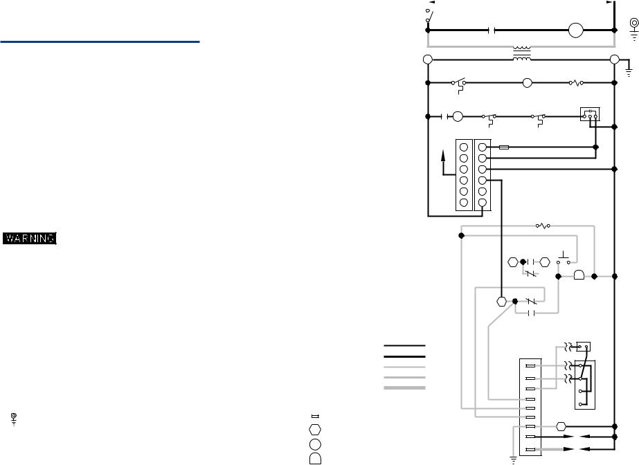
Wiring — water boilers |
|
|
LADDER WIRING DIAGRAM |
EQUIPMENT |
||
|
|
120 V.A.C. |
|
(NOTE 7) |
|||
|
|
|
|
|
|
GROUND |
|
|
|
|
|
SERVICE |
|
|
|
CIRCULATOR |
|
|
|
|
SWITCH |
|
1K2 |
|
|
|
|
|
|
|
|
|
||
|
|
|
|
|
|
|
|
|
Figure 5 |
|
|
|
|
|
|
|
|
|
|
|
|
R |
|
|
|
C |
Water boiler wiring — |
|
|
|
|
TRANSFORMER |
|
||
|
|
THERMOSTAT |
|
RELAY COIL |
||||
ladder and schematic diagrams |
|
|
|
|||||
|
|
|
1K |
|||||
|
|
|
|
|
G |
|||
|
|
|
|
|
|
|
|
|
|
|
|
|
|
|
|
|
MANUAL |
|
|
|
|
|
|
MANUAL |
|
RESET |
|
|
|
|
1K1 |
|
RESET |
HIGH |
PROBE LWCO |
|
|
|
|
|
HIGH LIMIT |
LIMIT |
|
|
|
|
|
|
|
Y |
|
|
|
|
|
|
|
CABLE |
|
|
|
|
|
|
|
|
TO |
|
FUSE |
|
|
|
|
|
|
DAMPER |
|
|
|
|
|
|
|
|
3 |
3 |
|
|
|
|
|
|
|
|
|
|
||
|
|
|
|
|
5 |
5 |
|
|
|
|
|
|
|
4 |
4 |
|
|
|
|
|
|
|
2 |
2 |
|
|
|
|
|
|
|
6 |
6 |
|
|
|
|
|
|
|
1 |
1 |
|
|
|
|
|
|
|
|
|
2K |
|
|
ELECTRICAL SHOCK HAZARD, CAN CAUSE SEVERE |
|
|
|
|
|
|
|
|
INJURY OR DEATH. DISCONNECT POWER |
|
|
|
|
|
|
|
|
BEFORE INSTALLING AND/OR SERVICING. |
|
|
|
|
SEE NOTE 10 |
|
|
|
|
|
|
|
|
|
||
NOTES: |
|
|
|
|
|
2K4 |
|
|
|
|
|
|
A1 |
A2 |
|
||
1. ALL WIRING MUST BE INSTALLED IN ACCORDANCE WITH: |
|
|
|
|
|
|||
|
|
|
|
|
|
|
||
|
A. U.S.A. - NATIONAL ELECTRICAL CODE AND ANY OTHER NATIONAL, STATE OR LOCAL |
|
|
|
|
N/A |
R |
|
|
CODE REQUIREMENTS. |
|
|
|
|
|
|
|
|
|
|
|
|
|
2K3 |
|
|
|
B. CANADA - C.S.A. C22.1 CANADIAN ELECTRICAL CODE PART 1 AND ANY OTHER |
|
|
|
|
|
|
|
|
|
|
|
|
|
|
|
|
|
NATIONAL, PROVINCIAL OR LOCAL CODE REQUIREMENTS. |
|
|
|
|
|
2K2 |
|
|
|
|
|
|
|
|
|
|
2. ALL CONTACTS SHOWN WITHOUT POWER APPLIED-OFF SHELF CONDITION. |
|
|
|
|
1 |
|
|
|
|
|
|
|
|
|
|
||
3. IF ORIGINALWIRE AS SUPPLIED WITH THE APPLIANCE MUST BE REPLACED, |
|
|
|
|
|
2K1 |
|
|
|
o |
|
|
|
|
|
|
|
|
TYPE 105 C OR IT’S EQUIVALENT MUST BE USED. |
|
|
|
|
|
|
PILOT |
4. REFER TO CONTROL COMPONENT INSTRUCTIONS PACKED WITH BOILER FOR APPLICATION |
|
|
|
|
|
SOLENOID |
||
|
|
|
|
|
VALVE |
|||
|
INFORMATION. |
|
LOW VOLTAGE FIELD |
|
|
|
|
|
|
|
|
|
|
|
|
||
5. THERMOSTAT - FOR SINGLE ZONE SYSTEMS, THERMOSTAT ANTICIPATOR SETTING IS 0.40 AMPS. |
HIGH VOLTAGE FIELD |
|
|
|
|
|||
|
FOR MULTIPLE ZONE SYSTEMS USING ZONE VALVES OR CIRCULATORS, REFER |
|
|
|
|
|||
|
LOW VOLTAGE FACTORY |
|
MV |
|
TH |
|||
|
TO COMPONENT MANUFACTURER’S INSTRUCTIONS FOR APPLICATION WIRING AND |
|
|
|||||
|
|
|
|
|||||
|
|
|
|
|
||||
|
THERMOSTAT ANTICIPATOR SETTING. |
|
HIGH VOLTAGE FACTORY |
|
MV/PV |
|
TR |
|
|
EMCS - FOR EMCS CONNECTION IN PLACE OF THERMOSTAT, REFER TO EMCS |
|
|
|||||
|
|
|
|
|
|
|
||
|
INSTALLATION/OPERATING MANUAL. |
|
IGNITION CABLE |
|
PV |
|
D+ |
|
|
|
|
|
|
|
|
|
|
6. L.W.C.O., HIGH LIMITS, WIRED IN SERIES. |
|
|
|
|
|
ALARM |
D |
|
|
|
|
|
|
|
|
ALARM |
|
|
|
|
|
|
|
|
|
|
7. |
DENOTES FIELD INSTALLED CHASSIS GROUND. |
|
|
IGNITION CONTROL MODULE TERMINAL. |
|
|
24V |
ROBERTSHAW |
|
|
|
|
|
GAS VALVE |
|||
|
|
|
|
|
|
|||
|
|
|
|
IGNITION CONTROL PANEL TERMINAL |
|
24V (G) |
2 |
|
8. PILOT LEADWIRES ARE NOT FIELD REPLACEABLE. REPLACE |
|
|
|
|
|
|
||
|
|
|
|
SENSE |
|
|
||
|
PILOT ASSEMBLY IF NECESSARY. |
|
|
|
|
|
|
|
|
|
|
TRANSFORMER TERMINAL. |
|
|
|
SENSOR |
|
|
|
|
|
|
SPARK |
|
||
9. CIRCULATOR NOT USED WITH GRAVITY HOT WATER. |
|
|
|
|
|
|
||
|
|
|
|
|
|
|
||
10. ALARM CONTACT RATINGS: 15 AMP @ 250 VAC. |
550-225-026/0199 |
R |
IGNITION CONTROL PANEL LAMP |
|
|
|
IGNITOR |
|
|
|
|
|
|
||||

677/0299-110-550 Number Part
SCHEMATIC WIRING DIAGRAM
EQUIPMENT
GROUND (NOTE 7)
|
|
(NOTE 6) |
|
|
|
|
MANUAL |
|
MANUAL |
HIGH |
|
RESET |
|
RESET |
LIMIT |
HIGH LIMIT |
PROBE LWCO |
||
|
BK |
|
BK |
BK |
BK |
|
THERMOSTAT |
||
|
OR EMCS |
|
||
|
|
|
||
BK |
BK |
(NOTE 5) |
G |
|
|
|
|
||
|
SERVICE |
Y |
W |
|
|
SWITCH |
|
||
|
G |
G |
|
|
(BY OTHERS) |
|
G |
G |
|
|
|
|
|
|
H |
|
C |
R |
|
|
BK |
BK |
||
|
BK |
|
||
|
|
|
TRANSFORMER |
|
|
|
|
120/24 V.A.C. |
|
N |
|
|
|
G |
|
|
|
|
|
|
|
W |
|
PLUG-IN |
|
|
Y |
|
|
|
|
|
|
DPST |
W |
Y |
|
|
RELAY |
CIRCULATOR |
JUNCTION BOX |
CABLE |
||
(NOTE 9) |
|
|
||
|
|
TO |
||
|
|
|
|
|
|
|
WIRE NUTS (3) |
DAMPER |
|
|
|
|
|
|
MOMENTARY |
|
|
|
|
|
SWITCH |
|
|
|
|
R |
R |
|
|
|
|
|
R |
IMPULSE |
|
|
|
|
|
|
RELAY |
|
|
|
W |
|
|
|
|
|
|
|
|
|
R |
|
|
|
|
|
R |
|
|
|
|
|
|
G |
|
|
|
|
|
G |
R |
|
|
|
|
|
|
Y |
|
|
|
|
|
|
R |
Y |
|
|
|
|
|
|
|
|
|
|
|
G |
|
R |
|
|
|
|
|
R |
|
|
|
|
|
TERMINAL |
|
|
|
|
A1 |
BLOCK |
|
1 |
2 |
|
A2 |
|
|
Y |
|
|
|
|
|
DAMPER CONNECTOR |
|
|
|
NOTE 10 |
|
|
|
|
|
|
|
R
D+
D
TH TR W
ROBERTSHAW
GAS VALVE
PRE-WIRED PANEL
W
BK
PILOT
SOLENOID
VALVE
BK |
W |
R |
UNIVERSAL SPARK
IGNITION CONTROL
MV
MV/PV
PV
R
ALARM
R
ALARM
Y
24V
G
24V (GND)
SENSE
SPARK
W O
PILOT
(NOTE 8)
EGH-105 to EGH-125 Control Supplement |
CSD-1 control system — Natural gas |
11
 Loading...