


Model No. WEEVSY39120
Serial No.
Write the serial number in the space above for reference.
Serial Number Decal (Under Seat)
QUESTIONS?
As a manufacturer, we are committed to providing complete customer satisfaction. If you have questions, or if there are missing or damaged parts, please call:
08457 089 009
Or write:
ICON Health & Fitness, Ltd. Unit 4
Revie Road Industrial Estate Revie Road
Beeston
Leeds, LS11 8JG UK
email: csuk@iconeurope.com
 CAUTION
Read all precautions and instructions in this manual before using this equipment. Save this manual for reference.
USER'S MANUAL
Class HC Fitness Product


 Visit our website at
www.iconeurope.com
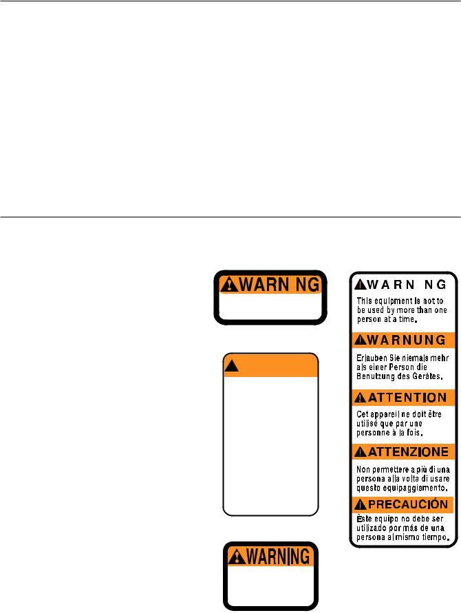
TABLE OF CONTENTS
WARNING DECAL PLACEMENT . . . . . . . . . . . . . . . . . . . . . . . . . . . . . . . . . . . . . . . . . . . . . . . . . . . . . . . . . . . . . .2 IMPORTANT PRECAUTIONS . . . . . . . . . . . . . . . . . . . . . . . . . . . . . . . . . . . . . . . . . . . . . . . . . . . . . . . . . . . . . . . .3 BEFORE YOU BEGIN . . . . . . . . . . . . . . . . . . . . . . . . . . . . . . . . . . . . . . . . . . . . . . . . . . . . . . . . . . . . . . . . . . . . . .4 ASSEMBLY . . . . . . . . . . . . . . . . . . . . . . . . . . . . . . . . . . . . . . . . . . . . . . . . . . . . . . . . . . . . . . . . . . . . . . . . . . . . . . .5 ADJUSTMENTS . . . . . . . . . . . . . . . . . . . . . . . . . . . . . . . . . . . . . . . . . . . . . . . . . . . . . . . . . . . . . . . . . . . . . . . . . .21 WEIGHT RESISTANCE CHART . . . . . . . . . . . . . . . . . . . . . . . . . . . . . . . . . . . . . . . . . . . . . . . . . . . . . . . . . . . . . .23 TROUBLESHOOTING AND MAINTENANCE . . . . . . . . . . . . . . . . . . . . . . . . . . . . . . . . . . . . . . . . . . . . . . . . . . .24 CABLE DIAGRAMS . . . . . . . . . . . . . . . . . . . . . . . . . . . . . . . . . . . . . . . . . . . . . . . . . . . . . . . . . . . . . . . . . . . . . . .25 ORDERING REPLACEMENT PARTS . . . . . . . . . . . . . . . . . . . . . . . . . . . . . . . . . . . . . . . . . . . . . . . . . .Back Cover
Note: A PART IDENTIFICATION CHART and a PART LIST/EXPLODED DRAWING are attached at the centre of this manual. Remove the PART IDENTIFICATION CHART and the PART LIST/EXPLODED DRAWING before beginning assembly.
WARNING DECAL PLACEMENT
The warning decals shown at the right have been placed on the weight system in the locations shown on page 4. If a decal is missing or illegible, please call our Customer Service Department at 08457 089 009 and order a free replacement decal. Place the decal on the weight system in the location shown.
Warning Decal No. 1 |
|
Warning Decal No. 4 |
||
|
|
|
|
|
|
|
|
|
|
|
|
|
|
|
|
|
|
|
|
Keep clear this area.
Warning Decal No. 2
! WARNING
• Misuse of this product may result in serious injury.
• Read user’s manual and follow all warnings and operating instructions prior to use.
• Do not allow children on or around machine.
• Replace label if damaged, illegible, or removed.
Warning Decal No. 3
Keep hands and fingers clear of this area.
2

IMPORTANT PRECAUTIONS
 WARNING: To reduce the risk of serious injury, read the following important precautions before using the weight system.
1.Read all instructions in this manual and in the accompanying literature before using the weight system.
2.It is the responsibility of the owner to ensure that all users of the weight system are adequately informed of all precautions.
3.The weight system is intended for home use only. Do not use the weight system in an commercial, rental, or institutional setting.
4.Use the weight system only on a level surface. Cover the floor beneath the weight system to protect the floor.
5.Make sure all parts are properly tightened each time you use the weight system. Replace any worn parts immediately.
6.Keep children under the age of 12 and pets away from the weight system at all times.
7.The weight system is designed to support a a maximum user weight of 115 kg (250 lbs.).
8.Always wear athletic shoes for foot protection.
9.Keep hands and feet away from moving parts.
10.Always disconnect the lat bar from the weight system when performing an exercise that does not use the lat bar.
11.Never release the press arm, butterfly arms, military press arm, leg lever, leg press plate, lat bar or nylon strap whilst weights are raised. The weights will fall with great force.
12.Always stand on a foot plate when performing an exercise that could cause the weight system to tip.
13.Keep your hands away from the leg press upright when the military press arm is being used. Your hand could become pinched between the leg press upright and military press arm.
14.Make sure that the cables remain on the pulleys at all times. If the cables bind whilst you are exercising, stop immediately and make sure that the cables are on all of the pulleys.
15.If you feel pain or dizziness at any time whilst exercising, stop immediately and begin cooling down.
 WARNING: Before beginning this or any exercise program, consult your physician. This is especially important for persons over the age of 35 or persons with pre-existing health problems. Read all instructions before using. ICON assumes no responsibility for personal injury or property damage sustained by or through the use of this product.
3
BEFORE YOU BEGIN
Thank you for selecting the versatile WEIDER® PRO 9450 weight system. The PRO 9450 weight system offers a selection of weight stations designed to develop every major muscle group of the body. Whether your goal is to tone your body, build dramatic muscle size and strength, or improve your cardiovascular system, the PRO 9450 weight system will help you to achieve the specific results you want.
For your benefit, read this manual carefully before using the weight system. If you have additional
questions, please call our Customer Service Department toll-free at 08457 089 009. To help us assist you, please note the product model number and serial number before calling. The model number is WEEVSY39120. The serial number can be found on a decal attached to the weight system (see the front cover of this manual).
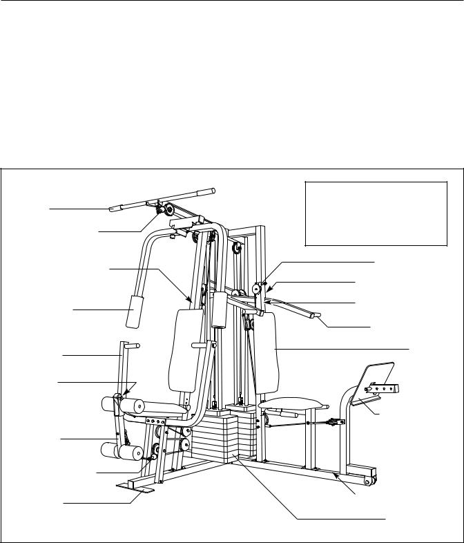
Before reading further, please review the drawing below and familiarise yourself with the parts that are labelled.
|
ASSEMBLED DIMENSIONS: |
|
Lat Bar |
Height: |
193 cm (76 in.) |
|
Width: 226 cm (89 in.) |
|
High Pulley Station |
Length: 163 cm (64 in.) |
|
|
|
|
Warning Decal No. 2 |
|
Ab Pulley Station |
|
|
|
|
|
Warning Decal No. 4 |
Butterfly Arm |
|
Warning Decal No. 2 |
|
|
|
|
|
Military Press Arm |
Press Arm |
|
Backrest |
|
|
|
Warning |
|
|
Decal No. 3 |
|
|
|
|
Leg Press Plate |
Leg Lever |
|
|
Low Pulley Station |
|
|
Foot Plate |
|
Warning Decal No. 1 |
|
|
Weight Stacks |
|
4 |
|
ASSEMBLY
Before beginning assembly, carefully read the following information and instructions:
•Due to the many features of the weight system, assembly will require several hours. By setting aside plenty of time and by deciding to make the task enjoyable, assembly will go smoothly. You may want to assemble the weight system over a couple of evenings.
•Assembly requires two people.
•Place all parts of the weight system in a cleared area and remove the packing materials; do not dispose of the packing materials until assembly is completed.
•Assembly is divided into four stages: 1) frame assembly, 2) arm assembly, 3) cable assembly, and 4) seat assembly. The hardware for each stage is packaged separately.
•Wait until you begin each assembly stage to open the parts bag labelled for that assembly stage.
•As you assemble the weight system, be sure that all parts are oriented as shown in the drawings.
•Tighten all parts as you assemble them, unless instructed to do otherwise.
•For help identifying the small parts used in assembly, use the PART IDENTIFICATION
CHART located in the centre of this manual.
Note: Some small parts may have been preattached for shipping. If a part is not in the parts bag, check to see if it has been pre-attached.
THE FOLLOWING TOOLS (NOT INCLUDED) ARE REQUIRED FOR ASSEMBLY:
• two adjustable wrenches
• one standard screwdriver
• one phillips screwdriver
• one rubber mallet
•lubricant, such as grease or petroleum jelly, and soapy water will also be needed.
•Assembly will be more convenient if you have the following tools: A socket set, a set of open-end or closed-end wrenches, or a set of ratchet wrenches.
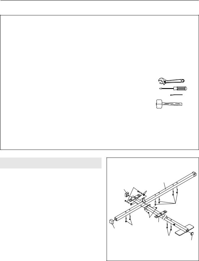
FRAME ASSEMBLY |
1 |
|
|
1. Before beginning, make sure that you have read |
|
|
5 |
and understand the information in the box above. |
|
|
|
|
11 |
|
|
|
51 |
8 |
|
Locate and open the parts bag labelled “FRAME |
|
||
|
|
||
|
|
|
|
ASSEMBLY.” |
|
|
|
Press two 2” Square Outer Caps (51) onto the |
|
|
1 |
Stabiliser (5) in the indicated locations. Press a 2” |
|
|
|
Square Inner Cap (27) into the end of the Base (4). |
|
|
|
Insert six 5/16” x 2 1/2” Carriage Bolts (1) up through |
|
|
3 |
|
1 |
4 |
|
the Stabiliser (5). Insert two 5/16” x 2 1/2” Carriage |
51 |
|
|
|
|
||
Bolts up through the Base (4). |
|
|
1 |
|
|
|
|
Attach the Base (4) to the Stabiliser (5) with two |
|
|
27 |
5/16” x 2 3/4” Bolts (11), two 5/16” Washers (8), and |
|
|
|
two 5/16” Nylon Locknuts (3). Do not tighten the |
|
|
|
Nylon Locknuts yet. |
|
|
|
5
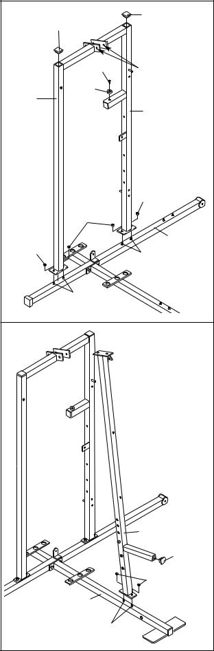
2.Slide the Rear Upright (74) and the Leg Press Upright (56) onto the indicated 5/16” x 2 1/2” Carriage Bolts (1) in the Stabiliser (5). The high side of the brackets on the Rear Upright and Leg Press Upright should be on the side shown.
Hand tighten four 5/16” Nylon Locknuts (3) onto the Carriage Bolts. Do not tighten the Nylon
Locknuts yet.
Press a 2” Square Inner Cap (27) into the Leg Press Upright (56). Press a 2” Square Inner Cap into the Rear Upright (74).
Attach the Rubber Bumper (91) to the Leg Press Upright (56) with the #8 x 1/2” Self-tapping Screw (87).
3.Slide the Front Upright (42) onto the 5/16” x 2 1/2” Carriage Bolts (1) in the Base (4). Hand tighten a 5/16” Nylon Locknut (3) onto each Carriage Bolt.
Do not tighten the Nylon Locknuts yet.
Press a 1” Square Inner Cap (6) into the Front Upright (42).
6
2 |
|
27 |
|
27 |
|
|
|
|
|
87 |
High Sides |
|
|
|
|
91 |
of Brackets |
74 |
|
|
|
|
|
|
|
56 |
|
|
3 |
|
3 |
|
|
|
5 |
3 |
|
1 |
|
|
|
|
1 |
|
3 |
|
|
|
|
42 |
|
|
6 |
|
|
3 |
|
4 |
|
|
|
1 |
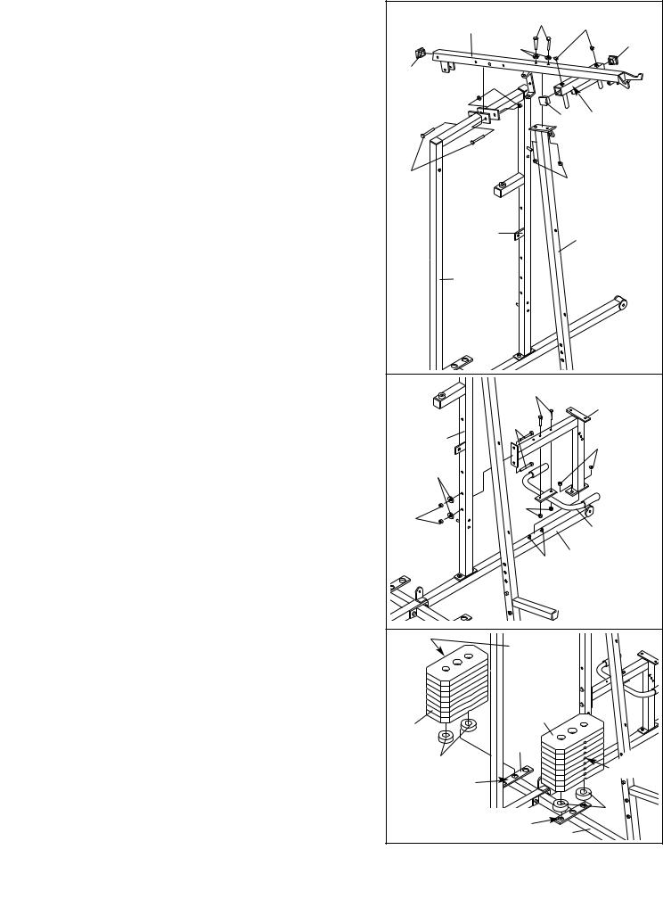
4.Press a 2” Square Inner Cap (27) into the end of the Top Frame (55). Press a 1 3/4” Square Inner Cap (44) into each end of the crossbar on the Top Frame. Press two Round Inner Caps (75) into the top of the crossbar.
Attach the Top Frame (55) to the Rear Upright (74) and the Leg Press Upright (56) with two 5/16” x
2 3/4” Bolts (11) and two 5/16” Nylon Locknuts (3).
Attach the Top Frame (55) to the Front Upright (42) with two 5/16” x 2 3/4” Bolts (11), two 5/16” Washers (8), and two 5/16” Nylon Locknuts (3).
5.Slide the Leg Press Seat Frame (79) onto the indicated 5/16” x 2 1/2” Carriage Bolts (1) in the Stabiliser (5). Hand tighten two 5/16” Nylon Locknuts (3) onto the Carriage Bolts.
Attach the other end of the Leg Press Seat Frame (79) to the Leg Press Upright (56) with two 5/16” x 2 3/4” Bolts (11), two 5/16” Washers (8), and two 5/16” Nylon Locknuts (3).
Attach the Handle (82) to the Leg Press Seat Frame (79) with two 5/16” x 2 1/2” Carriage Bolts
(1) and two 5/16” Nylon Locknuts (3).
Tighten all 5/16” Nylon Locknuts (3) used in steps 1–5.
6.Set two Weight Bumpers (19) on the bracket on the Base (4) as shown. Set two Weight Bumpers on the bracket on the Stabiliser (5).
Stack eight Weights (25) onto each set of Weight Bumpers (19). Be sure that the pin grooves are on the indicated side of each stack of Weights.
Be careful not to tip either stack of Weights (25) until step 8 is complete.
7
4 |
11 |
|
75 |
55 |
|
||
|
|
||
|
|
|
|
|
8 |
|
44 |
|
|
|
|
27 |
|
|
|
3 |
|
|
|
|
|
44 |
Crossbar |
11 |
|
3 |
|
|
|
|
|
56 |
|
|
42 |
74 |
|
|
|
5 |
1 |
|
|
|
|
|
|
|
|
|
79 |
|
11 |
|
|
56 |
|
|
3 |
8 |
|
|
|
3 |
3 |
|
|
|
|
82 |
|
|
|
|
|
|
1 |
5 |
|
|
|
|
|
6 |
Pin |
|
|
|
Grooves |
|
|
25 |
25 |
|
|
|
|
|
|
|
5 |
|
|
19 |
|
|
Pin |
Bracket |
|
|
Grooves |
|
|
|
|
Bracket |
|
19 |
|
4 |
|
||
|
|
|
|
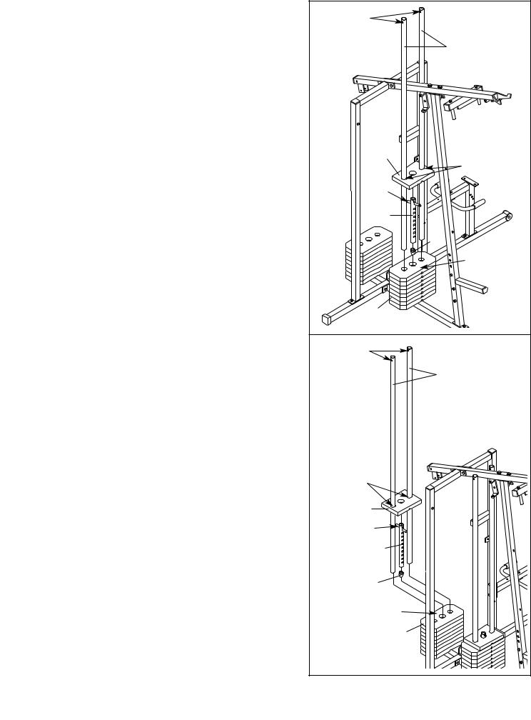
7. Press a Weight Tube Bumper (64) into the end of a |
7 |
|
|
Weight Tube (63). Insert the Weight Tube into the |
Holes |
||
|
|||
front stack of Weights (25). Be sure that the pin |
|
|
|
on the Weight Tube is sitting in the pin grooves |
|
62 |
|
in the top Weight. |
|
||
Lubricate the inside of the holes in the Top Weight |
|
|
|
(65). Set the Top Weight onto the front stack of |
|
|
|
Weights (25). Insert both Long Weight Guides (62) |
|
|
|
into the stack of Weights. Be sure that the holes |
|
|
|
in the Weight Guides are at the top, as shown. |
|
|
|
|
|
65 |
|
|
|
Lubricate |
|
|
|
Pin |
|
|
|
63 |
|
|
|
64 |
|
|
|
Pin Grooves |
|
|
|
25 |
|
8. Press a Weight Tube Bumper (64) into the end of |
8 |
Holes |
|
the other Weight Tube (63). Insert the Weight Tube |
|||
|
|||
into the rear stack of Weights (25). Be sure that |
|
|
|
the pin on the Weight Tube is sitting in the pin |
|
73 |
|
grooves in the top Weight. |
|
|
|
Lubricate the inside of the holes in the other Top |
|
|
|
Weight (65). Set the Top Weight onto the rear stack |
|
|
|
of Weights (25). Insert both Short Weight Guides |
|
|
|
(73) into the stack of Weights. Be sure that the |
|
|
|
holes in the Weight Guides are at the top, as |
|
|
|
shown. |
|
|
|
|
|
Lubricate |
|
|
|
65 |
|
|
|
Pin |
|
|
|
63 |
|
|
|
64 |
|
|
|
Pin Grooves |
|
|
|
25 |
|
|
8 |
|
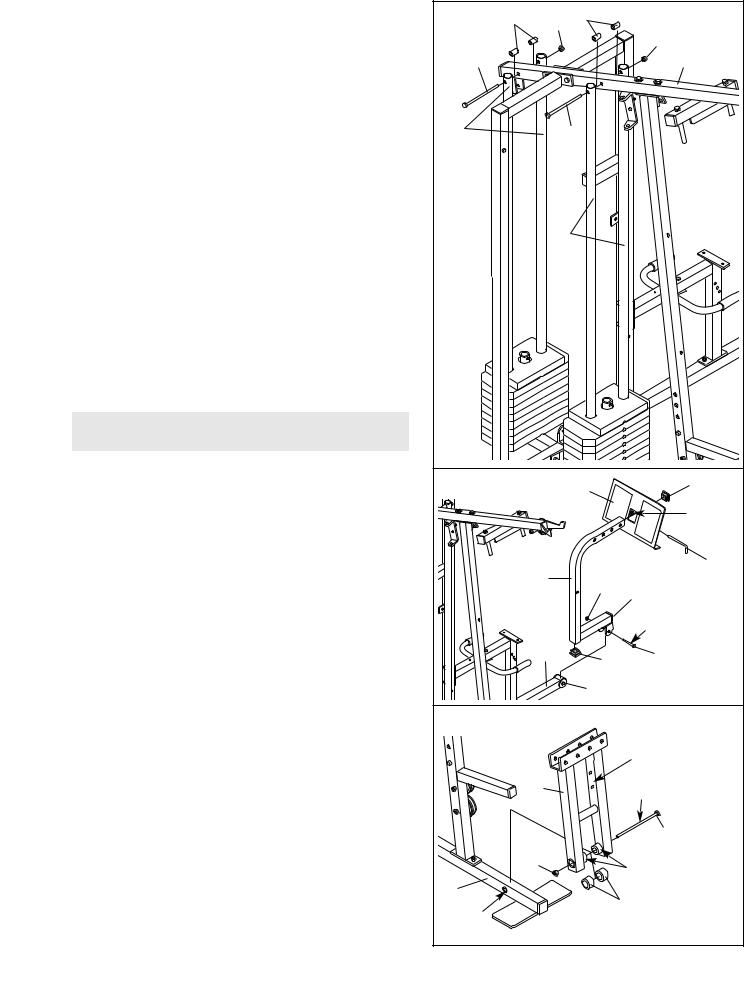
9. |
Attach the upper ends of the Short Weight Guides |
9 |
61 |
|
61 |
|
|
|
|
(73) to the Top Frame (55) with a 5/16” x 6” Bolt |
3 |
|
|
|
|||
|
|
|
|
|
||||
|
(60), two 1/2” x 3/4” Spacers (61), and a 5/16” |
|
|
|
|
|
|
3 |
|
Nylon Locknut (3). |
60 |
|
|
|
|
|
55 |
|
|
|
|
|
|
|
||
|
Attach the upper ends of the Long Weight Guides |
|
|
|
|
|
|
|
|
(62) to the Top Frame (55) with a 5/16” x 6” Bolt |
|
|
|
|
|
|
|
|
(60), two 1/2” x 3/4” Spacers (61), and a 5/16” |
73 |
|
60 |
|
|
|
|
|
Nylon Locknut (3). |
|
|
|
|
|||
|
|
|
|
62 |
|
|
|
|
|
ARM ASSEMBLY |
|
|
|
|
|
|
|
10. |
Locate and open the parts bag labelled “ARM |
10 |
|
|
95 |
|
|
27 |
|
ASSEMBLY.” |
|
|
|
|
|||
|
|
|
|
|
|
|||
|
Be sure there is a Bushing (98) in each side of the |
|
|
|
|
|
|
Welded |
|
|
|
|
|
|
|
Tube |
|
|
Stabiliser (5). Press a 2” Square Inner Cap (27) into |
|
|
|
|
|
|
|
|
|
|
|
|
|
|
|
|
|
each end of the Leg Press Arm (96). |
|
|
|
|
|
|
97 |
|
|
|
96 |
|
|
|
|
|
|
Lubricate a 3/8” x 3 1/4” Bolt (67). Attach the Leg |
|
|
|
21 |
|
27 |
|
|
|
|
|
|
|
|||
|
Press Arm (96) to the Stabiliser (5) with the Bolt and |
|
|
|
|
|
|
|
|
|
|
|
|
|
|
|
|
|
a 3/8” Nylon Locknut (21). Do not over tighten the |
|
|
|
|
|
|
Lubricate |
|
Nylon Locknut; the Leg Press Arm must be able |
|
|
|
|
|
|
|
|
|
|
|
|
|
|
|
|
|
to pivot freely. |
|
5 |
|
|
27 |
67 |
|
|
|
|
|
|
||||
|
|
|
|
|
|
|
||
|
Align the welded tubes on the Leg Press Plate (95) |
|
|
|
98 |
|
|
|
|
with one set of holes in the Leg Press Arm (96). |
|
|
|
|
|
||
|
|
|
|
|
|
|
|
|
|
Attach the Leg Press Plate to the Leg Press Arm |
11 |
|
|
|
|
|
Holes must |
|
with the Press Pin (97). |
|
|
|
|
|
|
|
|
|
|
|
|
|
|
|
be on |
11. |
Press a 1” x 7/8” Plastic Bushing (90) onto each |
|
|
|
|
|
|
this side |
|
|
|
|
|
|
|
||
|
welded spacer on the Press Frame (17). Slide the |
|
17 |
|
|
|
Lubricate |
|
|
Press Frame into place onto the Base (4). Note: |
|
|
|
|
|||
|
|
|
|
|
|
|||
|
This will be a tight fit. The Plastic Bushings |
|
|
|
|
|
|
|
|
should fit on each end of the indicated tube in |
|
|
|
|
|
|
59 |
|
the Base. Make sure that the indicated holes are |
|
|
|
|
|
|
|
|
|
|
|
|
|
|
|
|
|
on the side shown. |
|
21 |
|
|
|
|
Welded Spacers |
|
|
|
|
|
|
|
||
|
|
|
|
|
|
|
|
|
|
Lubricate the 3/8” x 8” Bolt (59). Attach the Press |
4 |
|
|
|
|
|
90 |
|
Frame (17) to the Base (4) with the Bolt and a 3/8” |
Tube |
|
|
|
|
|
|
|
Nylon Locknut (21). |
|
|
|
|
|
|
|
|
|
|
|
|
|
|
|
|
9
12.Press a 1” Round Inner Cap (49) into one of the Press Arms (46). Press a 1 3/4” Square Inner Cap
(44)into the Press Arm.
Attach the Press Arm (46) to one side of the Press Frame (17) with two 5/16” x 2 1/2” Bolts (22) and two 5/16” Nylon Locknuts (3).
Assemble the other Press Arm (46) in the same manner.
13.Identify the Right Arm (48) and the Left Arm (47). Note the position of the welded bracket on each Arm. Arm identification is very important for step 14.
Attach a “V”-Pulley (50) and a Long Cable Trap (31) to the Right Arm (48) with a 3/8” x 2 1/2” Bolt (86) and a 3/8” Nylon Locknut (21). Do not tighten the
Nylon Locknut yet.
Attach a “V”-Pulley (50) and a Long Cable Trap (31) to the Left Arm (47) in the same manner.
14.Lubricate both axles on the Top Frame (55).
Slide the Right Arm (48) onto the right axle on the Top Frame (55). Note: Be careful not to confuse the Right Arm with the Left Arm (47); refer to step 13 to identify the Right Arm. Be sure that the upper end of the Right Arm is behind the indicated bracket on the Top Frame.
See the inset drawing. Tap two 1” Retainers (69) and a 1” Round Cover Cap (70) onto the axle. Be sure that the teeth on the Retainers bend toward the Round Cover Cap, as shown.
Attach the Left Arm (47) in the same manner.
Press 1 3/4” Square Inner Caps (44) into the lower ends of the Right and Left Arms (47, 48). Wet the lower end of each Arm with soapy water. Slide a 10” Pad (45) onto the lower end of each Arm.
10
12 |
|
44 |
49 |
|
|
|
|
|
|
|
46 |
|
22 |
|
|
46 |
|
|
|
|
|
3 |
|
|
|
17 |
|
13 |
86 |
31 |
|
|
31 |
50 |
|
|
|
|
|
Welded |
50 |
|
|
|
|
47 |
|
Brackets |
|
|
|
|
|
|
|
|
|
21 |
|
48 |
|
|
|
14 |
|
|
|
|
55 |
Bracket |
|
|
|
|
47 |
|
|
Lubricate |
|
|
|
Axle |
|
|
48 |
|
|
|
|
69 |
|
|
|
|
45 |
|
|
70 |
|
|
|
|
44 |
|
44 |
Axle |
|
|
45 |
|
69 |
|
|
|
70 |
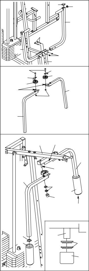
15. See the inset drawing. Attach the Military Press Arm (84) to the Pivot Arm (80) with two 5/16” x
2 1/4” Bolts (33) and two 5/16” Nylon Locknuts (3).
Press two 1 1/2” Square Inner Caps (32) into the indicated end of the Military Press Arm (84). Press two 1” Round Inner Caps (49) into the Military Press Arm.
Attach the Pivot Arm (80) to the Rear Upright (74) with a 3/8” x 3 1/4” Bolt (67) and a 3/8” Nylon Locknut (21).
CABLE ASSEMBLY
16.Locate and open the parts bags labelled “CABLE ASSEMBLY” and “PULLEYS.”
During steps 16 through 36, refer to the CABLE DIAGRAMS on pages 25 and 26 of this manual to verify proper cable routing. Before beginning this section, fully unwind the four Cables. Identify the four Cables by comparing the lengths and ends of the Cables. The approximate length of each Cable is listed (in inches) after the key number in the drawing.
IMPORTANT: Whilst assembling the cables, do not over tighten the bolts and nuts attaching the pulleys; the pulleys must be able to turn freely.
17.Locate the High Cable (58). Wrap the High Cable around a 3 1/2” Pulley (15). Attach the Pulley to the Top Frame (55) with a 3/8” x 3 3/4” Bolt (88) and a 3/8” Nylon Locknut (21). Be sure that the end of the Cable with the ball is on the indicated side of the Pulley and that the Cable is between the Pulley and the hook.
11
15 |
|
32 |
|
|
49 |
|
|
32 |
21 |
|
84 |
|
|
|
|
80 |
|
|
67 |
|
74 |
|
56 |
|
33 |
|
|
80 |
|
|
|
84 |
|
3 |
|
16 |
|
|
|
|
23—206cm |
|
|
(81 1/4”) |
|
|
58—371cm |
|
|
(146 1/4”) |
|
|
72— 603cm |
|
|
(237 1/2”) |
|
|
78— 160cm |
|
|
(63 1/8”) |
17 |
|
|
21 |
55 |
58 |
|
||
|
|
|
|
15 |
|
Ball |
Hook |
88 |
 Loading...