


Model No. WEEVSY49810.0 |
|
Serial No. |
USERʼS MANUAL |
space above for reference. |
|
Write the serial number in the |
|
Serial Number |
Decal |
QUESTIONS?
If you have questions, or if there are missing parts, please contact us:
UK
Call: 08457 089 009
From Ireland: 053 92 36102
Website: www.iconsupport.eu
E-mail: csuk@iconeurope.com
Write:
ICON Health & Fitness, Ltd. c/o HI Group PLC
Express Way
Whitwood, West Yorkshire
WF10 5QJ
UK
AUSTRALIA
Call: 1-800-237-173
E-mail:
australiacc@iconfitness.com
CAUTION |
|
Read all precautions and instruc- |
|
tions in this manual before using |
|
this equipment. Keep this manual |
www.iconeurope.com |
for future reference. |
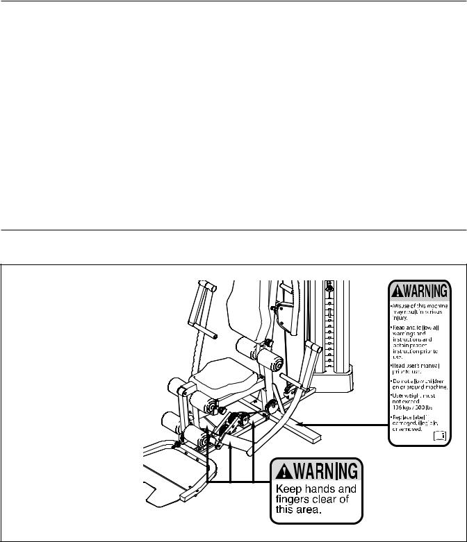
TABLE OF CONTENTS
WARNING DECAL PLACEMENT . . . . . . . . . . . . . . . . . . . . . . . . . . . . . . . . . . . . . . . . . . . . . . . . . . . . . . . . . . . . . .2 IMPORTANT PRECAUTIONS . . . . . . . . . . . . . . . . . . . . . . . . . . . . . . . . . . . . . . . . . . . . . . . . . . . . . . . . . . . . . . . .3 BEFORE YOU BEGIN . . . . . . . . . . . . . . . . . . . . . . . . . . . . . . . . . . . . . . . . . . . . . . . . . . . . . . . . . . . . . . . . . . . . . .4 PART IDENTIFICATION CHART . . . . . . . . . . . . . . . . . . . . . . . . . . . . . . . . . . . . . . . . . . . . . . . . . . . . . . . . . . . . . .5 ASSEMBLY . . . . . . . . . . . . . . . . . . . . . . . . . . . . . . . . . . . . . . . . . . . . . . . . . . . . . . . . . . . . . . . . . . . . . . . . . . . . . . .7 ADJUSTMENT . . . . . . . . . . . . . . . . . . . . . . . . . . . . . . . . . . . . . . . . . . . . . . . . . . . . . . . . . . . . . . . . . . . . . . . . . . .34 WEIGHT RESISTANCE CHART . . . . . . . . . . . . . . . . . . . . . . . . . . . . . . . . . . . . . . . . . . . . . . . . . . . . . . . . . . . . . .37 CABLE DIAGRAM . . . . . . . . . . . . . . . . . . . . . . . . . . . . . . . . . . . . . . . . . . . . . . . . . . . . . . . . . . . . . . . . . . . . . . . . .38 MAINTENANCE . . . . . . . . . . . . . . . . . . . . . . . . . . . . . . . . . . . . . . . . . . . . . . . . . . . . . . . . . . . . . . . . . . . . . . . . . .39 EXERCISE GUIDELINES . . . . . . . . . . . . . . . . . . . . . . . . . . . . . . . . . . . . . . . . . . . . . . . . . . . . . . . . . . . . . . . . . . .40 PART LIST . . . . . . . . . . . . . . . . . . . . . . . . . . . . . . . . . . . . . . . . . . . . . . . . . . . . . . . . . . . . . . . . . . . . . . . . . . . . . .43 EXPLODED DRAWING . . . . . . . . . . . . . . . . . . . . . . . . . . . . . . . . . . . . . . . . . . . . . . . . . . . . . . . . . . . . . . . . . . . .45 ORDERING REPLACEMENT PARTS . . . . . . . . . . . . . . . . . . . . . . . . . . . . . . . . . . . . . . . . . . . . . . . . . .Back Cover
WARNING DECAL PLACEMENT
This drawing shows the location(s) of the warning decal(s). If a decal is missing or illegible, see the front cover of this manual and request a free replacement decal. Apply the decal in the location shown. Note: The decal(s) may not be shown at actual size.
WEIDER is a registered trademark of ICON IP, Inc.
2

IMPORTANT PRECAUTIONS
WARNING: To reduce the risk of serious injury, read all important precautions and ructions in this manual and all warnings on your weight system before using your weight sys-
tem. ICON assumes no responsibility for personal injury or property damage sustained by or through the use of this product.
1. Before beginning any exercise program, consult your physician. This is especially important for persons over age 35 or persons with pre-existing health problems.
2. Use the weight system only as described in this manual.
3. It is the responsibility of the owner to ensure that all users of the weight system are adequately informed of all precautions.
4. The weight system is intended for home use only. Do not use the weight system in a commercial, rental, or institutional setting.
5. Keep the weight system indoors, away from moisture and dust. Do not put the weight system in a garage or covered patio, or near water.
6. Place the weight system on a level surface, with a mat beneath it to protect the floor or carpet. Make sure that there is enough clearance around the weight system to mount, dismount, and use the weight system.
7. Inspect and properly tighten all parts regularly. Replace any worn parts immediately.
8. Keep children under age 12 and pets away from the weight system at all times.
9. The weight system should not be used by persons weighing more than 300 lbs. (136 kg).
3
BEFORE YOU BEGIN
Thank you for selecting the versatile WEIDER® 9900 I weight system. The weight system offers a selection of weight stations designed to develop every major muscle group of the body. Whether your goal is to tone your body, build dramatic muscle size and strength, or improve your cardiovascular system, the weight system will help you to achieve the specific results you want.
For your benefit, read this manual carefully before using the weight system. If you have questions after
reading this manual, please see the front cover of this manual. To help us assist you, note the product model number and serial number before contacting us. The model number and the location of the serial number decal are shown on the front cover of this manual.
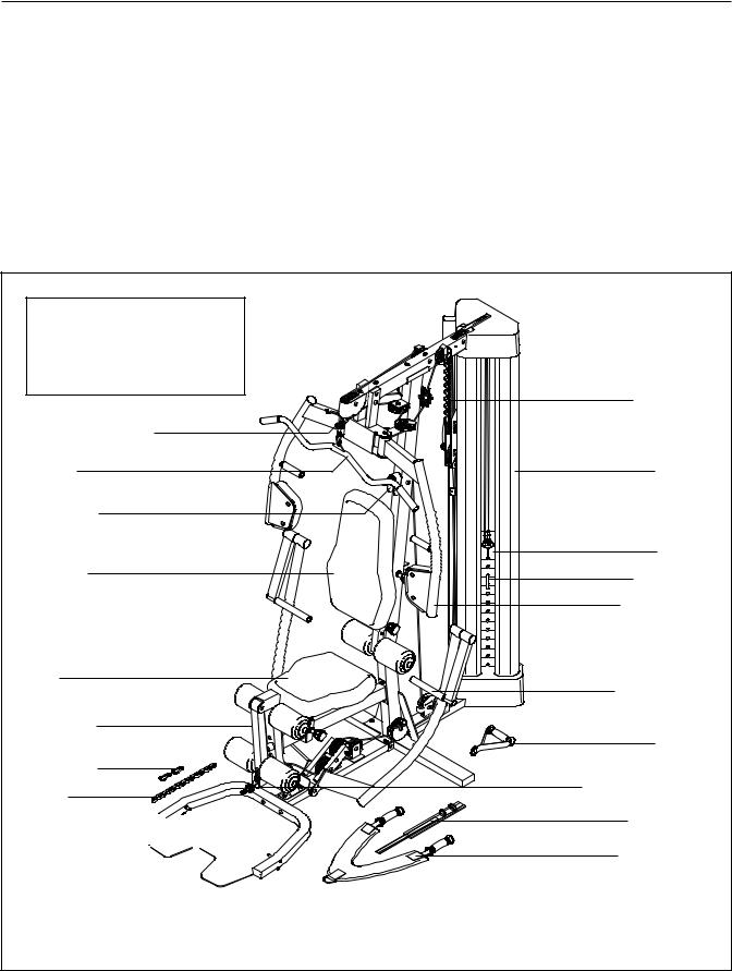
Before reading further, please review the drawing below and familiarize yourself with the parts that are labeled.
Assembled Dimensions:
Height: 6 ft. 11 in. (211 cm)
Width: 4 ft. 1 in. (124 cm)
Depth: 7 ft. 1 in. (216 cm)
High Pulley Station
Lat Bar
Ab Station
Backrest
Right Side
Seat
Leg Lever
Cable Clip
Chain
Foot Plate 


Burn Band |
Shroud |
Weight |
Weight Pin |
Butterfly Arm |
Left Side |
Press Handle |
Handle |
Low Pulley Station
Ankle Strap
Double Strap
Note: The terms “right side” and “left side” are used relative to a person sitting on the seat; they do not correspond to right and left on the drawings in this manual.
4
PART IDENTIFICATION CHART
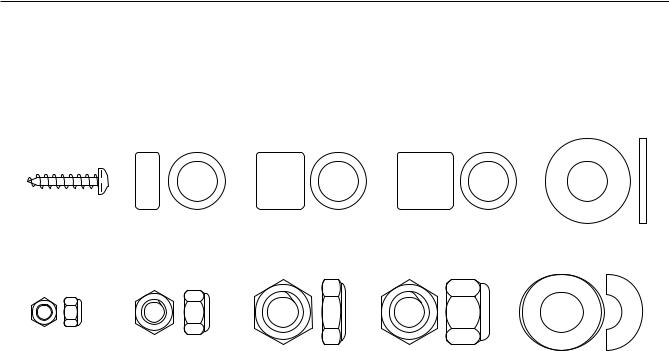
Refer to the drawings below to identify small parts used in assembly. The number in parentheses by each drawing is the key number of the part, from the PART LIST near the end of this manual. IMPORTANT:If you cannot find a part in the hardware kit, check to see if it has been preassembled. To avoid damaging parts, do not use power tools for assembly.
ST4.2 x 19mm |
6.35mm |
12.7mm |
14.8mm |
M10 Washer (88) |
Screw (90) |
Spacer (94) |
Spacer (73) |
Spacer (95) |
M4 Locknut |
M6 Locknut (87) |
M10 Jam Nut (99) |
M10 Locknut (74) |
M10 Curved |
(108) |
|
|
|
Washer (86) |
Continued on page 6
5
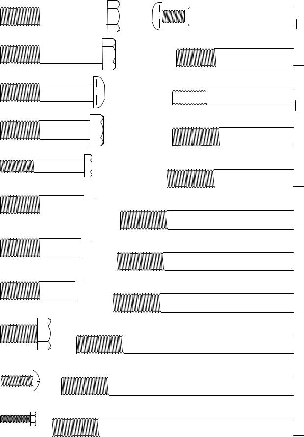
M10 x 57mm
Bolt (93)
M10 x 55mm
Bolt (79)
M10 x 50mm
Button Bolt (76)
M10 x 47mm
Bolt (91)
M6 x 45mm Bolt (85)
M10 x 45mm Bolt (98)
M10 x 43mm Bolt (65)
M10 x 40mm Bolt (97)
M10 x 20mm
Screw (84)
M6 x 16mm
Screw (62)
M4 x 12mm
Bolt (107)
M10 x 57mm Bolt Set (80) 
M10 x 63mm Bolt (89) 


 M8 x 65mm Button Screw (82)
M10 x 65mm Bolt (75) 
M10 x 68mm Bolt (66) 
M10 x 93mm Bolt (63) 
M10 x 95mm Bolt (78) 
M10 x 97mm Bolt (100) 
M10 x 117mm Bolt (64)  M10 x 125mm Bolt (83)
M10 x 130mm Bolt (11) 
6
ASSEMBLY
To make assembly easier, carefully read the following information and instructions:
•Assembly requires two persons.
•Because of its weight and size, assemble the weight system in the location where it will be used. Make sure that there is enough clearance to walk around the weight system.
•Place all parts in a cleared area and remove the packing materials. Do not dispose of the packing materials until assembly is completed.
•For help identifying small parts, use the PART IDENTIFICATION CHART on pages 5 and 6.
•The following tools (not included) may be required for assembly:
two adjustable wrenches one rubber mallet one standard screwdriver one Phillips screwdriver
Assembly may be more convenient if you have a socket set, a set of open-end or closed-end wrenches, or a set of ratchet wrenches.
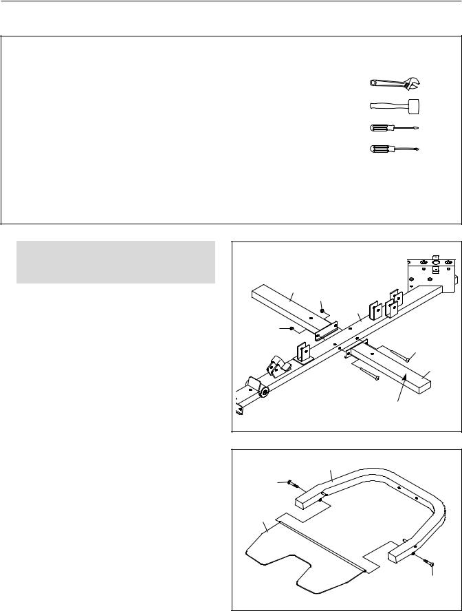
1. |
To make assembly easier, read the |
1 |
|
|
|
|
|
|
|
|
|
|
|
||
|
assembly tips in the box above. |
|
|
|
|
|
|
|
Orient the Base (1) and the Side Stabilizers (2) |
|
|
2 |
74 |
|
|
|
|
|
|
1 |
|
||
|
|
|
|
|
|
||
|
as shown. |
|
|
|
|
|
|
|
Attach the Side Stabilizers (2) to the Base (1) |
|
74 |
|
|
|
|
|
|
|
|
|
|
|
|
|
with two M10 x 95mm Bolts (78) and two M10 |
|
|
|
|
78 |
|
|
Locknuts (74). Do not fully tighten the |
|
|
|
|
|
|
|
|
|
|
|
|
2 |
|
|
Locknuts yet. |
|
|
|
|
|
|
|
|
|
|
|
|
78 Warning |
|
|
|
|
|
|
|
Decal |
|
2. Orient the U-stabilizer (3) and the Foot Plate (4) |
2 |
|
|
|
|
|
|
|
as shown. Make sure that the textured side of |
|
|
|
3 |
|
|
|
|
|
|
|
|
||
|
the Foot Plate is facing upward. |
|
82 |
|
|
|
|
|
|
|
|
|
|
|
|
|
Attach the Foot Plate (4) to the U-stabilizer (3) |
|
|
|
|
|
|
|
with two M8 x 65mm Button Screws (82). Do |
|
4 |
|
|
|
|
|
not overtighten the Screws; the Foot Plate |
|
|
|
|
|
|
|
must pivot easily. |
|
|
|
|
|
|
|
|
|
|
|
|
|
82 |
|
|
7 |
|
|
|
|
|
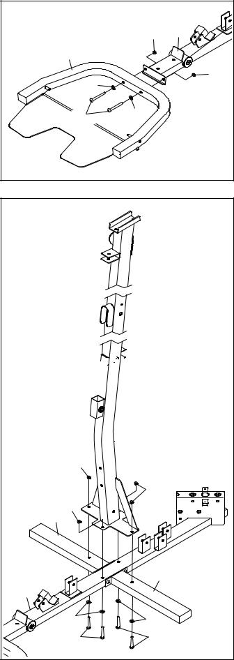
3. Attach the U-stabilizer (3) to the Base (1) with |
3 |
|
|
two M10 x 68mm Bolts (66), two M10 Washers |
|
|
|
|
|
|
|
(88), and two M10 Locknuts (74). |
|
74 |
1 |
|
|
||
|
3 |
|
|
|
88 |
|
74 |
|
|
|
|
|
66 |
88 |
|
|
|
|
|
4. Orient the Upright (5) as shown. |
4 |
|
|
|
|
|
|
Attach the Upright (5) to the Base (1) and the |
|
|
|
Side Stabilizers (2) with four M10 x 55mm Bolts |
|
|
|
(79), four M10 Washers (88), and four M10 |
|
|
|
Locknuts (74). Do not fully tighten the |
|
|
|
Locknuts yet. |
|
|
|
5


|
74 |
|
|
|
74 |
2 |
74 |
|
|
2 |
1 |
|
88 |
88 |
79 |
79 |
8 
5. Orient the Leg (10) as shown. |
|
5 |
|
|
|
|
|
|
|
|
|
|
|
|
|
|
|
|
|
Attach the Leg (10) to the Base (1) with two |
|
|
|
|
|
|
|
|
|
M10 x 55mm Bolts (79), two M10 Washers (88), |
|
|
|
|
|
|
|
|
|
and two M10 Locknuts (74). Do not fully |
|
|
|
|
|
|
|
|
|
tighten the Locknuts yet. |
|
|
|
|
10 |
|
|
|
|
|
|
|
|
|
|
|
|
|
|
|
|
|
|
|
74 |
|
|
|
|
|
|
|
74 |
|
|
|
|
|
|
|
|
|
1 |
|
|
88 |
|
|
|
|
|
|
|
88 |
|
|
|
|
|
|
|
|
|
|
|
|
|
|
|
|
|
|
|
|
|
79 |
|
|
|
6. Orient the Seat Tube (8) as shown. |
6 |
|
|
|
|
|
|
|
|
|
|
|
|
|
|
74 |
|
|
|
Attach the Leg (10) to the Seat Tube (8) with |
|
|
|
|
|
|
|
||
|
|
|
|
|
|
|
|
||
two M10 x 68mm Bolts (66), two M10 Washers |
|
|
|
|
8 |
|
|
|
|
(88), and two M10 Locknuts (74). |
Do not fully |
|
|
|
74 |
|
|
|
|
tighten the Locknuts yet. |
|
|
|
|
|
|
|
63 |
|
|
|
|
|
|
|
|
88 |
||
Attach the Seat Tube (8) to the Upright (5) with |
|
|
|
|
|
|
|||
|
|
|
|
|
|
|
|||
|
|
|
|
|
74 |
|
|
||
two M10 x 93mm Bolts (63), two M10 Washers |
|
10 |
|
|
|
5 |
|
||
(88), and two M10 Locknuts (74). |
Do not fully |
|
|
|
|
|
|
||
tighten the Locknuts yet. |
|
|
|
|
74 |
|
|
|
|
|
|
|
|
|
|
|
|
|
|
See steps 1, 4, 5, and 6. Tighten the M10 |
|
88 |
|
|
|
|
|
|
|
Locknuts (74). |
|
|
|
|
|
|
|
|
|
|
|
66 |
88 |
|
|
|
|
|
|
|
|
9 |
|
|
|
|
|
|
|
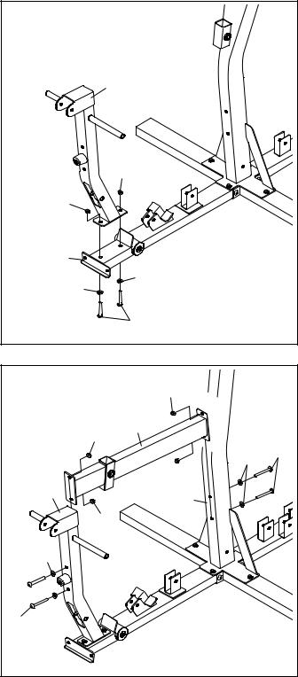
7. Apply some of the included grease to an M10 x |
7 |
80 |
|
|
|
|
|
57mm Bolt Set (80). |
|
Grease |
|
|
|||
Orient the Leg Lever (13) so that the high end of |
|
|
|
|
|||
|
|
|
80 |
|
|
||
the bracket is in the location shown. |
|
|
|
|
|
||
|
|
|
|
|
|
||
Attach the Leg Lever (13) to the Leg (10) with |
|
13 |
|
10 |
|
|
|
|
|
|
|
|
|
||
the M10 x 57mm Bolt Set (80). |
Make sure that |
|
|
|
|
|
|
the barrel of the Bolt Set is inserted through |
|
|
|
|
|
|
|
both sides of the bracket on the Leg. |
|
|
|
|
|
|
|
|
|
|
High |
|
|
|
|
|
|
|
End |
|
|
|
|
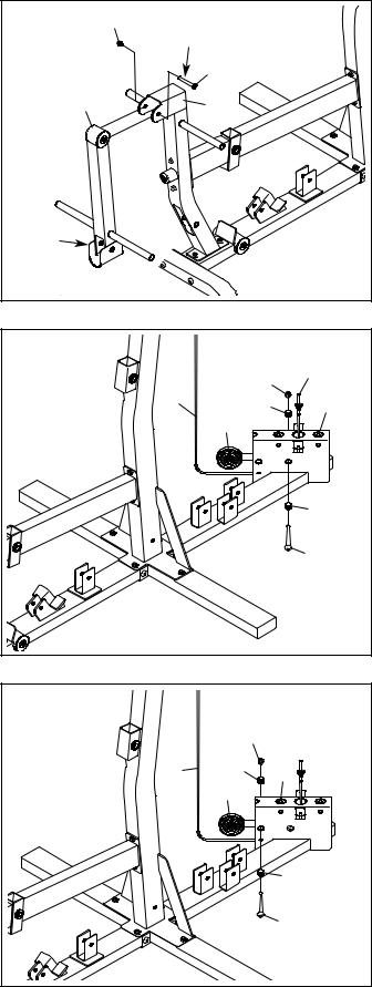
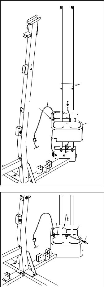
8. See the CABLE DIAGRAM on page 38 to |
8 |
|
|
|
|
|
|
identify the cables as you assemble them. |
|
|
|
|
Threaded |
||
|
|
|
|
|
|||
Identify the Burn Cable (45). |
|
|
|
|
|
74 |
End |
|
|
|
45 |
|
|
||
|
|
|
|
73 |
1 |
||
Identify the four Burn Pulleys (68), the three |
|
|
68 |
||||
|
|
|
|
|
|||
V-pulleys (not shown), and the twenty |
|
|
|
|
|
|
|
Pulleys (not shown). |
|
|
|
|
|
|
|
Route the threaded end of the Burn Cable (45) |
|
|
|
|
|
73 |
|
through the bracket on the Base (1) as shown. |
|
|
|
|
|
||
Attach a Burn Pulley (68) over the Burn Cable |
|
|
|
|
|
89 |
|
(45) inside the bracket on the Base (1) with an |
|
|
|
|
|
||
|
|
|
|
|
|
||
M10 x 63mm Bolt (89), two 12.7mm Spacers |
|
|
|
|
|
|
|
(73), and an M10 Locknut (74). |
|
|
|
|
|
|
|
9. Attach a second Burn Pulley (68) over the Burn |
9 |
|
|
|
|
|
|
Cable (45) inside the bracket on the Base (1) |
|
|
|
|
|
||
|
|
|
|
|
|
||
with an M10 x 63mm Bolt (89), two 12.7mm |
|
|
|
|
74 |
|
|
Spacers (73), and an M10 Locknut (74). |
|
|
|
|
|
||
|
|
|
|
|
|
||
|
|
|
|
45 |
73 |
1 |
|
|
|
|
|
|
68 |
|
|
|
|
|
|
|
|
|
73 |
|
|
|
|
|
|
|
89 |
|
|
10 |
|
|
|
|
|
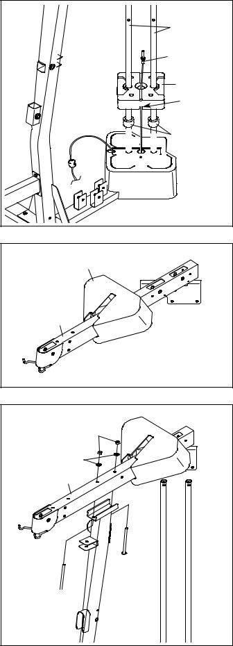
10.Orient the Weight Guides (31) so that the indicated holes are closer to the floor.
Insert the Weight Guides (31) into the holes in the Base (1). Attach each Weight Guide with an M10 x 63mm Bolt (89) and an M10 Locknut (74).
10
Holes
 31
31
74 |
74 |
|
1 |
89
11
11. Orient the Bottom Cover (28) so that the notch |
11 |
|
|
is in the indicated location. |
|
|
|
|
|
|
|
Slide the Bottom Cover (28) downward over the |
|
|
|
Weight Guides (31) and the Burn Cable (45). |
|
|
|
Make sure that the Burn Cable is routed as |
|
|
|
shown and is inserted into the notch in the |
|
|
|
Bottom Cover. |
|
|
|
|
|
|
31 |
|
|
45 |
|
|
Notch |
|
|
|
|
|
28 |
12. Make sure that the Burn Cable (45) is routed |
12 |
|
|
as shown. |
|
|
|
|
|
|
|
Attach the Bottom Cover (28) to the Base (1) |
|
|
90 |
with two ST4.2 x 19mm Screws (90). |
|
1 |
|
|
|
28 |
|
|
|
|
|
|
|
|
45 |
|
12 |
|
|
13. Slide a Bumper (40) onto each Weight Guide |
13 |
|
(31). |
|
|
|
31 |
|
Orient a Weight (30) so that the pin hole is in |
|
|
|
|
|
the indicated location. |
|
45 |
|
|
|
Then, slide the Weight (30) onto the Weight |
|
30 |
Guides (31). Route the end of the Burn Cable |
|
|
(45) upward through the center of the Weight. |
|
Pin Hole |
|
|
|
Repeat these actions with the other eleven |
|
|
Weights. |
|
40 |
|
|
14.Orient the Top Frame (6) and the Top Cover (27) as shown. Slide the Top Cover onto the Top Frame.
15.Attach the Top Frame (6) to the Upright (5) with two M10 x 93mm Bolts (63), two M10 Washers (88), and two M10 Locknuts (74). Do not fully tighten the Locknuts yet.
14 |
27 |
|
|
|
6 |
15 |
|
|
74 |
|
6 88 |
 63
63
 5
5
63
13
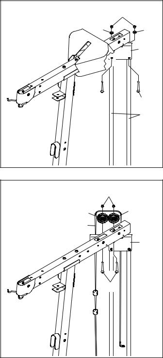
16.Attach the Top Frame (6) to the Weight Guides
(31)with two M10 x 43mm Bolts (65), two M10 Curved Washers (86), and two M10 Locknuts
See step 15. Tighten the M10 Locknuts (74).
17.Note: For clarity, the Top Cover (27) is not shown.
Route the Burn Cable (45) over two Burn Pulleys (68).
Attach each Burn Pulley (68) to the right side of the Top Frame (6) with an M10 x 40mm Bolt (97) and an M10 Locknut (74).
16 |
74 |
|
|
86 |
86 |
|
6 |
65 |
65 |
|
31 |
17 |
74 |
|
|
68 |
68 |
45 |
|
|
6 |
|
97 |
14
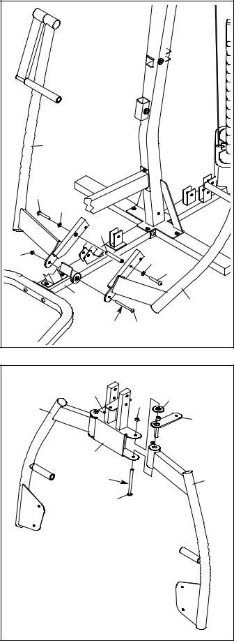
18. Apply grease to an M10 x 130mm Bolt (11). |
18 |
|
|
|
|
|
|
|
|
|
|
Identify the Left and Right Press Arms (17, 18) |
|
|
|
|
|
and orient them as shown. |
|
|
|
|
|
Insert the Press Arm Spacer (42) between the |
|
|
|
|
|
Left and Right Press Arms (17, 18) as shown. |
|
|
|
|
|
Attach the Left and Right Press Arms (17, 18) to |
|
|
|
|
|
the Base (1) with the M10 x 130mm Bolt (11) |
|
|
|
|
|
and an M10 Locknut (74). Do not overtighten |
|
|
|
|
|
the Locknut; the Press Arms must pivot eas- |
|
|
|
|
|
ily. |
|
|
18 |
|
|
|
|
|
|
|
|
Attach the Left and Right Press Arms (17, 18) |
|
|
|
|
|
with two M10 x 20mm Screws (84), two M10 |
|
|
|
|
|
Washers (88), and the Press Arm Spacer (42). |
|
84 |
|
|
|
|
|
88 |
|
|
|
|
|
|
|
|
|
|
|
|
42 |
|
|
|
74 |
|
|
88 |
84 |
|
|
|
|
||
|
|
|
1 |
|
17 |
|
|
|
|
|
|
|
|
|
Grease |
11 |
|
19. Identify the Butterfly Frame (7), the Left |
19 |
|
|
|
|
Butterfly Pulley Bracket (20), and the Left |
|
|
|
|
|
|
|
21 |
|
|
|
Butterfly Arm (15) and orient them as shown. |
|
|
74 |
52 |
|
|
|
16 |
|
||
Apply grease to an M10 x 130mm Bolt (11). |
|
|
|
||
|
|
|
20 |
||
|
|
|
|
||
|
|
|
|
|
|
Attach the Left Butterfly Arm (15) to the Butterfly |
|
|
|
|
|
Frame (7) with the M10 x 130mm Bolt (11), an |
|
|
7 |
|
|
Upper Butterfly Bushing (52), the Left Butterfly |
|
|
|
|
|
|
|
|
|
|
|
Pulley Bracket (20), and an M10 Locknut (74). |
|
|
Grease |
|
15 |
Do not overtighten the Locknut; the Butterfly |
|
|
|
||
Arm must pivot easily. |
|
|
11 |
|
|
|
|
|
|
|
|
Repeat this step to attach the Right Butterfly |
|
|
|
|
|
Arm (16) and the Right Butterfly Pulley |
|
|
|
|
|
Bracket (21). |
|
|
|
|
|
|
15 |
|
|
|
|
 Loading...