


9150
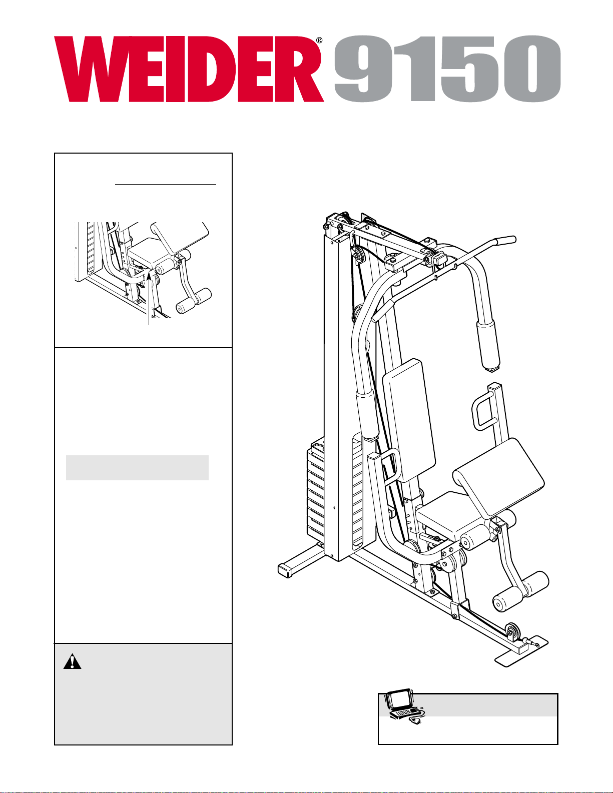
CAUTION
Read all precautions and instruc-
tions in this manual before using
this equipment. Save this manual
for future reference.
USER'S MANUAL
Model No.WEEVSY49220
Serial No.
(Write the serial number in the
space above for reference.)
Serial Number Decal (under seat)
www.iconeurope.com
Visit our website at
QUESTIONS?
As a manufacturer, we are
committed to providing com-
plete customer satisfaction. If
you have questions, or if there
are missing parts, please call:
Or write:
ICON Health & Fitness, Ltd.
Unit 4
Revie Road Industrial Estate
Revie Road
Beeston
Leeds, LS118JG
UK
email: csuk@iconeurope.com
08457 089 009

2
IMPORTANT PRECAUTIONS . . . . . . . . . . . . . . . . . . . . . . . . . . . . . . . . . . . . . . . . . . . . . . . . . . . . . . . . . . . . . 3
BEFORE YOU BEGIN . . . . . . . . . . . . . . . . . . . . . . . . . . . . . . . . . . . . . . . . . . . . . . . . . . . . . . . . . . . . . . . . . . . 4
ASSEMBLY . . . . . . . . . . . . . . . . . . . . . . . . . . . . . . . . . . . . . . . . . . . . . . . . . . . . . . . . . . . . . . . . . . . . . . . . . . . 5
ADJUSTMENTS . . . . . . . . . . . . . . . . . . . . . . . . . . . . . . . . . . . . . . . . . . . . . . . . . . . . . . . . . . . . . . . . . . . . . . 16
WEIGHT RESISTANCE CHART . . . . . . . . . . . . . . . . . . . . . . . . . . . . . . . . . . . . . . . . . . . . . . . . . . . . . . . . . . .18
TROUBLESHOOTING AND MAINTENANCE . . . . . . . . . . . . . . . . . . . . . . . . . . . . . . . . . . . . . . . . . . . . . . . . .19
CABLE DIAGRAMS . . . . . . . . . . . . . . . . . . . . . . . . . . . . . . . . . . . . . . . . . . . . . . . . . . . . . . . . . . . . . . . . . . . .20
EXERCISE GUIDELINES . . . . . . . . . . . . . . . . . . . . . . . . . . . . . . . . . . . . . . . . . . . . . . . . . . . . . . . . . . . . . . . .21
ORDERING REPLACEMENT PARTS . . . . . . . . . . . . . . . . . . . . . . . . . . . . . . . . . . . . . . . . . . . . . . . .Back Cover
Note: APART IDENTIFICATION CHART and a PART LIST/EXPLODED DRAWING are attached in the centre of
this manual. Remove the PART IDENTIFICATION CHART and PART LIST/EXPLODED DRAWING before begin-
ning assembly.
WEIDER is a registered trademark of ICON Health & Fitness, Inc.
TABLE OF CONTENTS
1. Read all instructions in this manual and in
the accompanying literature before using the
weight system. Use the weight system only
as described in this manual.
2. It is the responsibility of the owner to ensure
that all users of the weight system are ade-
quately informed of all precautions.
3. The weight system is intended for home use
only. Do not use the weight system in a com-
mercial, rental, or institutional setting.
4. Use the weight system only on a level sur-
face. Cover the floor or carpet beneath the
weight system to protect the floor.
5. Make sure that all parts are properly tight-
ened each time the weight system is used.
Replace any worn parts immediately.
6. Keep children under the age of 12 and pets
away from the weight system at all times.
7. Keep hands and feet away from moving parts.
8. Always wear athletic shoes for foot protec-
tion when using the weight system.
9. The weight system is designed to support a
maximum user weight of 136 kg (300 lbs.).
10. Never release the press arm, butterfly arms,
leg lever, lat bar, curl bar, handle, ab strap, or
ankle strap whilst weights are raised; the
weights will fall with great force.
11. Make sure that the cables remain on the pul-
leys at all times. If the cables bind whilst you
are exercising, stop immediately and make
sure that the cables are on all of the pulleys.
12. Always stand on the foot plate when per-
forming an exercise that could cause the
weight system to tip.
13. Always disconnect the lat bar from the
weight system when performing an exercise
that does not use the lat bar.
14. If you feel pain or dizziness at any time
whilst exercising, stop immediately and
begin cooling down.
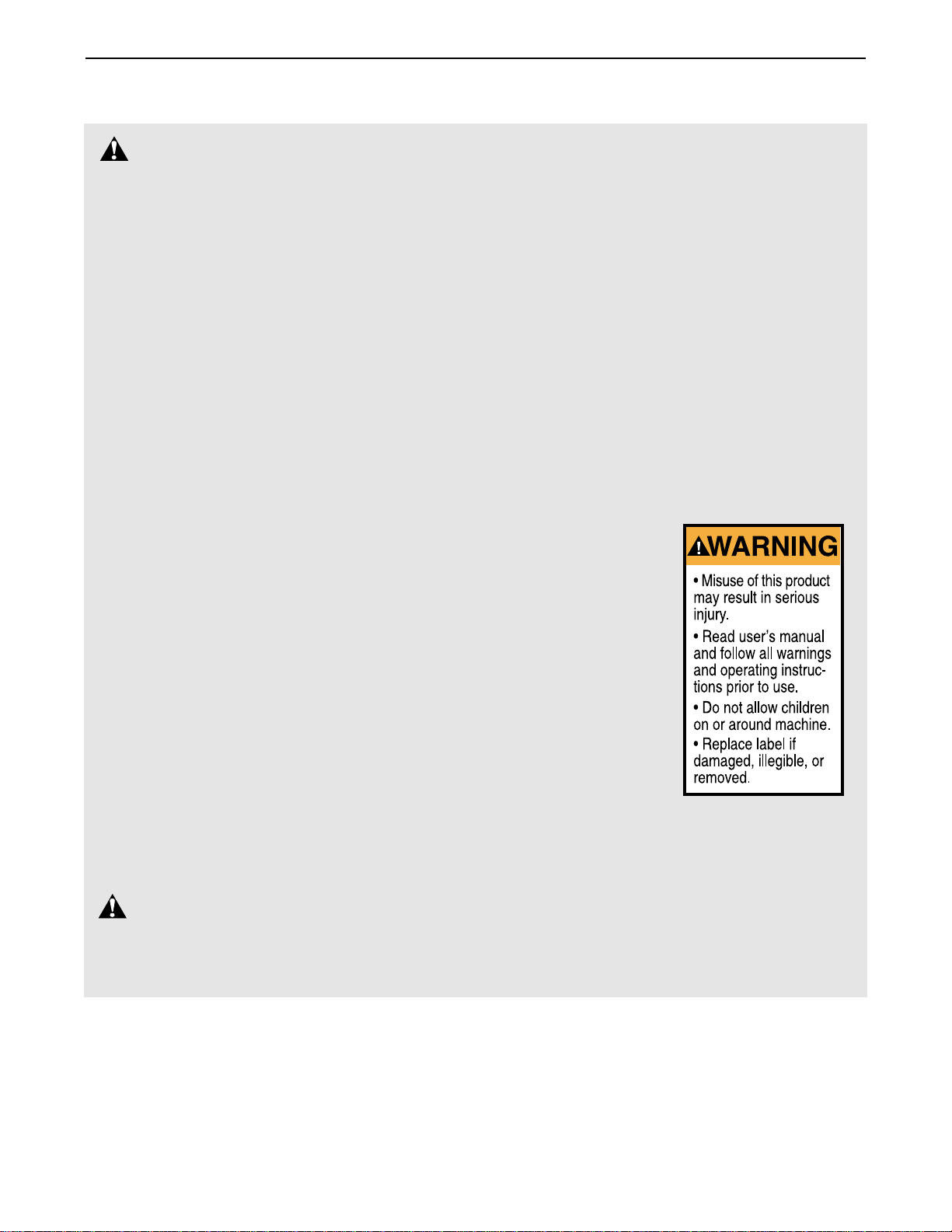
15. The decal shown
here has been
placed on the
weight system in
the location indicat-
ed on page 4. If the
decal is missing or
illegible, please call
our Customer
Service Department
toll-free at 08457
089 009 to order a
free replacement
decal. Apply the
decal in the indicat-
ed location.
WARNING:Before beginning this or any exercise program, consult your physician. This
is especially important for persons over the age of 35 or persons with pre-existing health problems.
Read all instructions before using. ICON assumes no responsibility for personal injury or property
damage sustained by or through the use of this product.
WARNING: To reduce the risk of serious injury, read the following important precautions
before using the weight system.
IMPORTANT PRECAUTIONS
3
4
BEFORE YOU BEGIN
Thank you for selecting the versatile WEIDER
®
9150
weight system. The WEIDER
®
9150 weight system
offers a selection of weight stations designed to devel-
op every major muscle group of the body. Whether
your goal is to tone your body, build dramatic muscle
size and strength, or improve your cardiovascular sys-
tem, the WEIDER
®
9150 will help you to achieve the
specific results you want.
For your benefit, read this manual carefully before
using the weight system. If you have questions after
reading this manual, please call our Customer Service
Department at 0845 089 009. To help us assist you,
please note the product model number and serial
number before calling. The model number is
WEEVSY49220. The serial number can be found on a
decal attached to the weight system (see the front
cover of this manual).
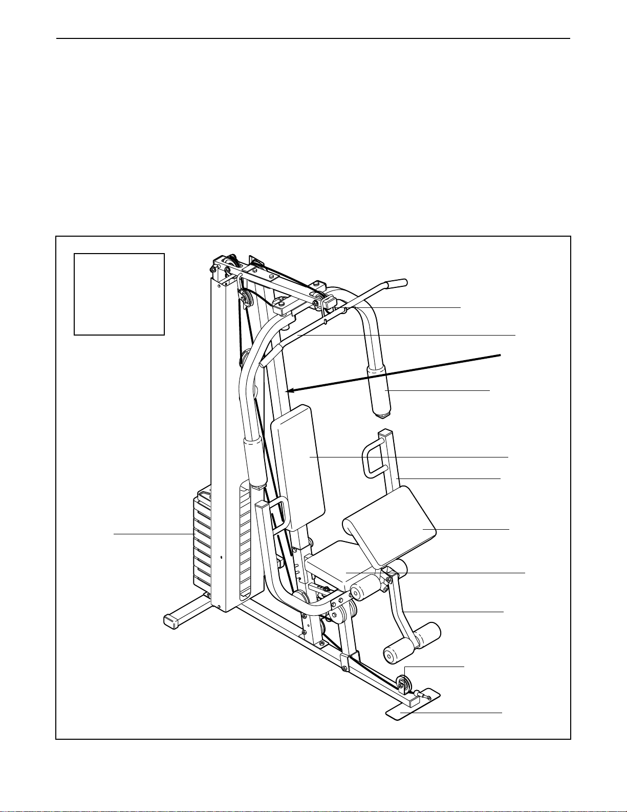
Before reading further, please review the drawing
below and familiarise yourself with the parts that are
labelled.
ASSEMBLED
DIMENSIONS:
Height: 73 in.
Width: 32 in.
Length: 56 in.
Foot Plate
Low Pulley Station
High Pulley Station
Leg Lever
Butterfly Arm
Lat Bar
Press Arm
Curl Pad
Weights
Seat
Backrest
Left Side
Right Side
Note: The terms “right side” and “left side”
are determined relative to a person sitting
on the seat; they do not correspond to right
and left on the drawings in this manual.
WARNING
DECAL
5
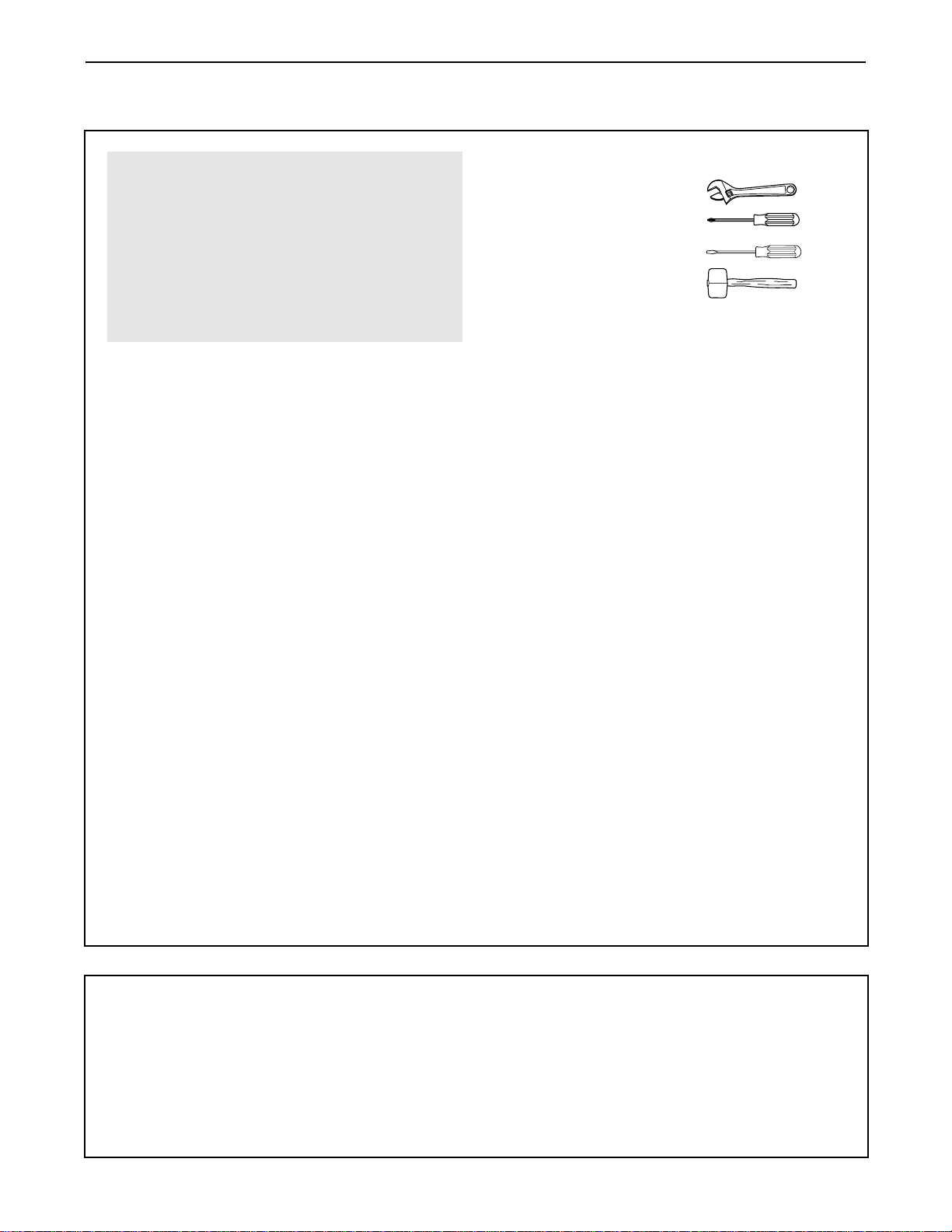
Make sure you have the following tools:
• Two adjustable spanners
• One standard screwdriver
• One phillips screwdriver
• One rubber mallet
• You will also need grease or petroleum jelly, a
small amount of soapy water, and clear tape or
masking tape.
Note: Assembly will be more convenient if you have
a socket set, a set of open-end or closed-end
wrenches, or a set of ratchet wrenches.
How to Identify Parts
To help you identify the small parts used in assembly,
we have included a PART IDENTIFICATION CHART
in the centre of this manual. Place the chart on the
floor and use it to easily identify parts during each
assembly step. Note: Some small parts may have
been pre-attached. If a part is not in the parts
bag, check to see if it has been pre-attached.
How to Orient Parts
As you assemble the weight system, make sure that
all parts are oriented exactly as shown in the draw-
ings.
Tightening Parts
Tighten all parts as you assemble them, unless
instructed to do otherwise.
Questions?
If you have questions after reading the assembly
instructions, please call our Customer Service
Department at 0845 089 009.
Assembly Requires Two Persons
For your convenience and safety, assemble the
weight system with the help of another person.
Set Aside Enough Time
Due to the many features of the weight system, the
assembly process will require several hours. By
setting aside plenty of time and by deciding to
make the task enjoyable, assembly will go smoothly.
You may want to assemble the weight system over
a couple of evenings.
Select a Location for the Weight System
Because of its weight and size, the weight system
should be assembled in the location where it will be
used. Make sure that there is enough room to walk
around the weight system as you assemble it.
How to Unpack the Box
To make assembly as easy as possible, we have
divided the assembly process into four stages. The
parts needed for each stage are found in individual
bags. Important: Wait until you begin each stage
to open the parts bag for that stage. Place all
parts of the weight system in a cleared area and
remove the packing materials. Do not dispose of
the packing materials until assembly is completed.
Make Assembly Easier for Yourself
Everything in this manual is designed to
ensure that the weight system can be assem-
bled successfully by anyone. Before begin-
ning assembly, make sure to read the
information on this page. This brief intro-
duction will save you much more time than
it takes to read it.
The Four Stages of the Assembly Process
Frame Assembly—You will begin by assembling
the base and the uprights that form the skeleton of
the weight system.
Arm Assembly—During this stage you will
assemble the arms and the leg lever.
Cable Assembly—During this stage you will
attach the cables and pulleys that connect the
arms to the weights.
Seat Assembly—During the final stage you will
assemble the seat and the backrest.
ASSEMBLY
6
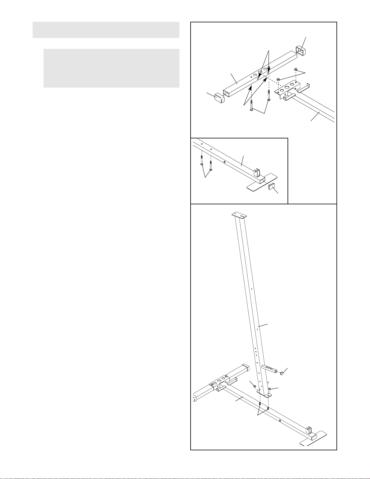
1.
Press a 40mm x 60mm Inner Cap (27) into the end
of the Base (4). Press two 40mm x 60mm Outer
Caps (73) onto the ends of the Stabiliser (5).
Insert four M10 x 55mm Carriage Bolts (1) up
through the Base (4) and the Stabiliser (5). Rest
the Base and the Stabiliser flat on the floor. Note:
Make sure that the indented holes in the
Stabilizer are on the bottom. Note that the
indicated holes are smaller than the holes on
the other side of the Stabilizer.
Attach the Base (4) to the Stabiliser (5) with the
indicated M10 x 55mm Carriage Bolts (1) and two
M10 Nylon Locknuts (21). Do not tighten the
Locknuts yet.
2. Press the 25mm Square Inner Cap (86) into the
Front Upright (42).
Attach the Front Upright (42) to the Base (4) with
the two M10 x 55mm Carriage Bolts (1) and two
M10 Nylon Locknuts (21). Do not tighten the
Locknuts yet.
Before beginning assembly, make sure you
have read and understood the information
on page 5. This introduction will save you
more time than it takes to read it.
FRAME ASSEMBLY
1
2
73
1
Small
Holes
Indents
21
5
1
4
4
73
27
86
42
21
21
4
1
7
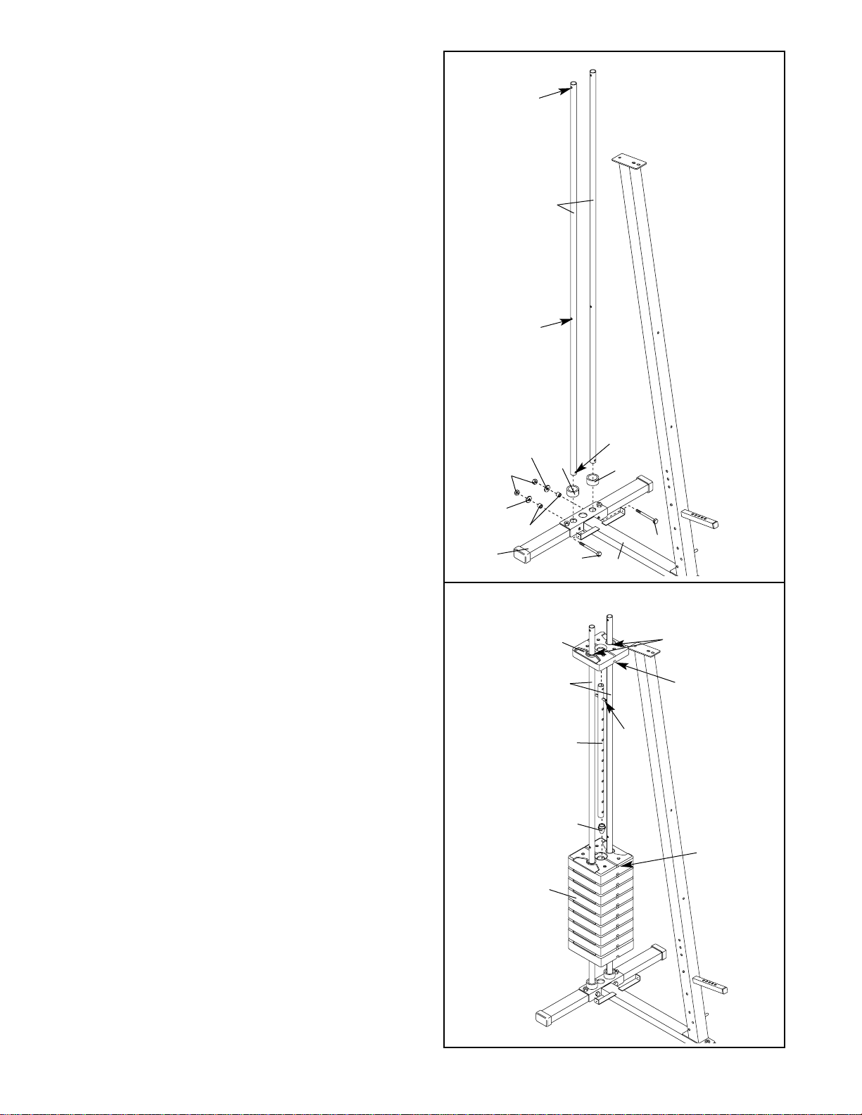
3. Insert the two Weight Guides (62) into the indicat-
ed holes in the Base (4) and the Stabiliser (5). Be
sure that the Weight Guides are oriented with
the holes in the positions shown. Attach the
Weight Guides to the Base and the Stabiliser with
two M10 x 78mm Bolts (14), two 17.5mm
Spacers (77), two M10 Washers (9), and two M10
Nylon Locknuts (21).
Slide two Weight Bumpers (19) onto the Weight
Guides (62).
3
62
Hole
14
14
4
21
5
77
9
9
19
19
Hole
Hole
4. Slide the nine Weights (25) onto the Weight
Guides (62). Be sure the pin grooves are on
the side shown.
Press the Weight Tube Bumper (72) into the bot-
tom of the Weight Tube (63). Insert the Weight
Tube into the centre hole in the Weights (25). Be
sure the pin on the Weight Tube rests in the
indicated pin groove.
Lubricate the indicated holes in the Top Weight
(56). Slide the Top Weight onto the Weight
Guides (62), with the pin groove on the side
shown.
4
63
72
62
25
Pin
Groove
Pin
Groove
Pin
Lubricate
56
8
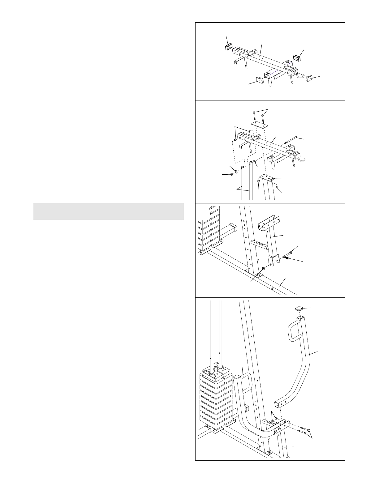
7. Lubricate the M10 x 92mm Bolt (16). Attach the
Press Frame (17) to the Base (4) with the Bolt
and an M10 Nylon Locknut (21). Do not over-
tighten the Nylon Locknut; the Press Frame
must be able to pivot easily.
7
4
21
16
Lubricate
17
5. Press four 40mm x 60mm Inner Caps (27) into
the ends of the Top Frame (55).
6. Hold the Top Frame (55) on top of the Front
Upright (42) between the Weight Guides (62).
Attach the Top Frame to the Front Upright with
two M10 x 60mm Bolts (7), the Support Plate
(71), and two M10 Nylon Locknuts (21).
Attach the Weight Guides (62) to the Top Frame
(55) with the M10 x 155mm Bolt (60), two 15mm
Spacers (61), two M10 Washers (9), and an M10
Nylon Locknut (21).
Tighten the M10 Nylon Locknuts (21) used in
steps 1 through 3 and step 6.
5
6
27
55
62
42
21
21
21
60
9
7
61
55
27
27
27
8. Press a 50mm Square Inner Cap (44) into the top
of a Press Arm (46). Attach the Press Arm to the
Press Frame (17) with two M10 x 70mm Bolts
(22) and two M10 Nylon Locknuts (21).
Repeat this step with the other Press Arm (46).
8
46
46
44
17
22
21
9
Arm Assembly
9
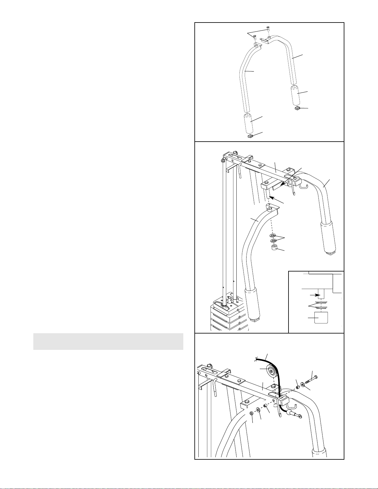
9. Press a 50mm Square Inner Cap (44) into the
end of the Right Butterfly Arm (48). Press a
Sleeve (89) into the Right Butterfly Arm.
Wet the lower end of the Right Butterfly Arm (48)
with soapy water. Slide a Large Foam Pad (45)
onto the Right Butterfly Arm.
Repeat this step with the Left Butterfly Arm
(47).
9
47
45
44
48
89
45
44
10. Lubricate the axles on the Top Frame (55). Orient
the Right Butterfly Arm (48) as shown and slide it
onto the right axle. Be sure the Butterfly Arm is
behind the bracket on the Top Frame.
Have a second person secure the Right Butterfly
Arm (48) to the axle with two 25mm Retainers
(68) and a 25mm Cover Cap (65). Note: Place
the Retainers on top of the inverted Cover
Cap, as shown in the inset drawing. Make
sure the teeth on the Retainers bend toward
the Cover Cap. Gently tap the Cover Cap onto
the axle.
Repeat this step with the Left Butterfly Arm
(47).
10
47
Lubricate
Axle
Bracket
65
65
48
55
68
68
Axle
Cable Assembly
11. For cable identification and routing during
steps 11 to 25, refer to the CABLE DIAGRAMS
on page 20. Do not overtighten the bolts and
locknuts that secure the pulleys; the pulleys
must be able to rotate freely.
Locate the High Cable (23), which has a ball on
one end and a bolt on the other. Route the bolt
end of the Cable up through the Top Frame (55)
and around a “V”-Pulley (6). Attach the Pulley
inside the Top Frame with an M10 x 75mm Bolt
(76), two 12.5mm Spacers (82), two M10
Washers (9), and an M10 Nylon Locknut (21).
6
23
11
55
21
76
9
9
82
82
 Loading...