


Model No. WECCSY1955.0
Serial No.
Write the serial number in the space above for future reference.
 Serial
 Nu
Nu m
m ber Decal (under seat)
QUESTIONS?
As a manufacturer, we are committed to providing complete customer satisfaction. If you have questions, or if parts are damaged or missing, PLEASE CONTACT OUR CUSTOMER SERVICE DEPARTMENT DIRECTLY.
1CALL-888TOLL-936-FREE:-4266
Mon.–Fri., 8:00 until 17:00 EST (excluding holidays)
OR E-MAIL US: customerservice@iconcanada.ca
CAUTION
Read all precautions and instructions in this manual before using this equipment. Save this manual for future reference.
USERʼS MANUAL
Visit our website at


 .weiderfitness.com

TABLE OF CONTENTS
WARNING DECAL PLACEMENT . . . . . . . . . . . . . . . . . . . . . . . . . . . . . . . . . . . . . . . . . . . . . . . . . . . . . . . . . . . . . 2 IMPORTANT PRECAUTIONS . . . . . . . . . . . . . . . . . . . . . . . . . . . . . . . . . . . . . . . . . . . . . . . . . . . . . . . . . . . . . . . . 3 BEFORE YOU BEGIN . . . . . . . . . . . . . . . . . . . . . . . . . . . . . . . . . . . . . . . . . . . . . . . . . . . . . . . . . . . . . . . . . . . . . . 4 ASSEMBLY . . . . . . . . . . . . . . . . . . . . . . . . . . . . . . . . . . . . . . . . . . . . . . . . . . . . . . . . . . . . . . . . . . . . . . . . . . . . . . 5 ADJUSTMENTS . . . . . . . . . . . . . . . . . . . . . . . . . . . . . . . . . . . . . . . . . . . . . . . . . . . . . . . . . . . . . . . . . . . . . . . . . . 16 WEIGHT RESISTANCE CHART . . . . . . . . . . . . . . . . . . . . . . . . . . . . . . . . . . . . . . . . . . . . . . . . . . . . . . . . . . . . . .18 CABLE DIAGRAMS . . . . . . . . . . . . . . . . . . . . . . . . . . . . . . . . . . . . . . . . . . . . . . . . . . . . . . . . . . . . . . . . . . . . . . .19 MAINTENANCE . . . . . . . . . . . . . . . . . . . . . . . . . . . . . . . . . . . . . . . . . . . . . . . . . . . . . . . . . . . . . . . . . . . . . . . . . .20 EXERCISE GUIDELINES . . . . . . . . . . . . . . . . . . . . . . . . . . . . . . . . . . . . . . . . . . . . . . . . . . . . . . . . . . . . . . . . . . 21 ORDERING REPLACEMENT PARTS . . . . . . . . . . . . . . . . . . . . . . . . . . . . . . . . . . . . . . . . . . . . . . . . . .Back Cover LIMITED WARRANTY . . . . . . . . . . . . . . . . . . . . . . . . . . . . . . . . . . . . . . . . . . . . . . . . . . . . . . . . . . . . . . Back Cover
Note: A PART IDENTIFICATION CHART and a PART LIST/EXPLODED DRAWING are attached in the center of this manual. Remove the PART IDENTIFICATION CHART and PART LIST/EXPLODED DRAWING before beginning assembly.
WARNING DECAL PLACEMENT
This drawing shows the location(s) of the warning decal(s). If a decal is missing or illegible, see the front cover of this manual and request a free replacement decal. Apply the decal in the location shown. Note: The decal(s) may not be shown at actual size.
Keep hands and |
Decal 3 |
fingers clear of |
|
ATTENTION |
|
this area. |
|
Gardez vos mains |
|
et vos doigts |
|
éloignés de cet |
|
endroit. |
|
Decal 3 |
|
Decal 2 


Decal 1—This decal is placed on both sides of the upright
Decal 2 |
Decal 1 |
|
WEIDER is a registered trademark of ICON IP, Inc.
2

IMPORTANT PRECAUTIONS
WARNING: To reduce the risk of serious injury, read the following important precautions before using the weight system.
1. Read all instructions in this manual and all warnings on the weight system before using the weight system. Use the weight system only as described in this manual.
2. It is the responsibility of the owner to ensure that all users of the weight system are adequately informed of all precautions.
3. The weight system is intended for home use only. Do not use the weight system in any commercial, rental, or institutional setting.
4. Keep the weight system indoors, away from moisture and dust. Place the weight system on a level surface, with a mat beneath it to protect the floor or carpet. Make sure that there is enough clearance around the weight system to mount, dismount, and use the weight system.
5. Inspect and properly tighten all parts regularly. Replace any worn parts immediately.
6. Keep children under age 12 and pets away from the weight system at all times.
7. Always wear athletic shoes for foot protection while exercising.
8. The weight system is designed to support a maximum user weight of 300 lbs (136 kg.).
9. Keep hands and feet away from moving parts.
WARNING: Before beginning this or any exercise program, consult your physician. This is especially important for persons over the age of 35 or persons with pre-existing health problems. Read all instructions before using. ICON assumes no responsibility for personal injury or property damage sustained by or through the use of this product.
3
BEFORE YOU BEGIN
Thank you for selecting the versatile WEIDER® 1200 weight system. The weight system offers a selection of weight stations designed to develop every major mus- cle group of the body. Whether your goal is to tone your body, build dramatic muscle size and strength, or improve your cardiovascular system, the weight system will help you to achieve the specific results you want.
For your benefit, read this manual carefully before using the weight system. If you have questions after
reading this manual, see the front cover of this manual. To help us assist you, please note the product model number and serial number before calling. The model number is WESY1955.0. The serial number can be found on a decal attached to the weight system (see the front cover of this manual).
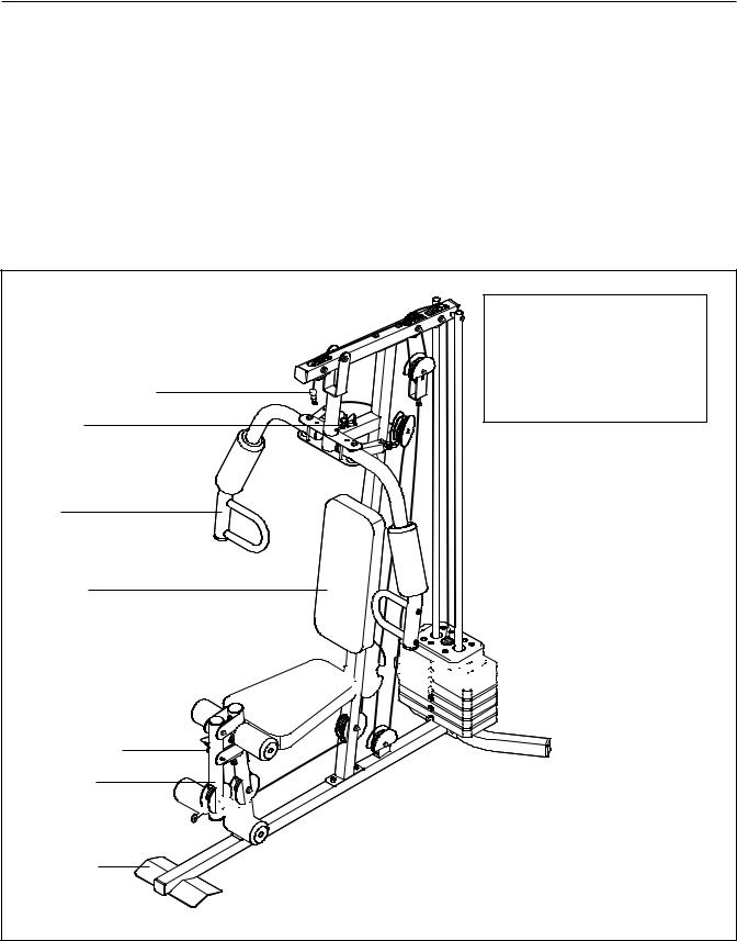
Before reading further, please review the drawing below and familiarize yourself with the parts that are labeled.
|
ASSEMBLED DIMENSIONS: |
||
|
Height: |
76 in. / |
193 cm |
|
Width: |
37 in. / |
94 cm |
|
Depth: |
65 in. / |
165 cm |
High Pulley Station |
Weight: 200 lbs. / 91 kg |
||
|
|
|
|
Arm Pin |
|
|
|
Arm
Left Side
Backrest
Right Side
Seat 


 Weights
Leg Lever Pin
Leg Lever
Low Pulley Station 


Foot Plate |
Note: The terms “right side” and “left side” are determined |
relative to a person sitting on the seat; they do not corre- |
|
|
spond to right and left on the drawings in the manual. |
4
ASSEMBLY
Make Assembly Easier for Yourself
Everything in this manual is designed to ensure that the weight system can be assembled successfully by almost anyone. Before beginning assembly, make sure to read the information on this page. This brief introduction will save you much more time than it takes to read it.
Assembly Requires Two Persons
For your convenience and safety, assemble the weight system with the help of another person.
Set Aside Enough Time
Assembling the weight system may require several hours. By deciding to make the task enjoyable, assembly will go smoothly. You may want to assemble the weight system over a couple of evenings.
Select a Location for the Weight System
Because of its weight and size, the weight system should be assembled in the location where it will be used. Make sure that there is enough clearance to walk around the weight system as you assemble it.
How to Unpack the Box
To make assembly as easy as possible, we have divided the assembly process into four stages. The parts needed for each stage are found in individual packages. Important: Wait until you begin each stage to open the parts package for that stage.
Place all parts of the weight system in a cleared area and remove the packing materials. Do not dispose of the packing materials until assembly is completed.
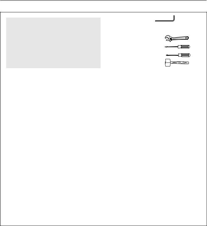
The included hex key(s) |
and grease, |
|
and the following tools (not included) may be |
||
required for assembly: |
|
|
• |
Two adjustable wrenches |
|
• |
One standard screwdriver |
|
• |
One phillips screwdriver |
|
• |
One rubber mallet |
|
• |
A small amount of soapy water, and clear tape or |
|
|
masking tape. |
|
Note: Assembly may be more convenient if you have a socket set, a set of open-end or closed-end wrenches, or a set of ratchet wrenches.
How to Identify Parts
Refer to the PART IDENTIFICATION CHART in the center of this manual to identify the small parts used in assembly. Note: Some small parts may have been pre-attached. If a part is not in the parts bag, check to see if it has been pre-attached.
How to Orient Parts
As you assemble the weight system, make sure all parts are oriented exactly as shown in the drawings.
Tightening Parts
Tighten all parts as you assemble them, unless instructed to do otherwise.
Questions?
If you have questions after reading the assembly instructions, please see the front cover of this manual.
|
|
|
|
|
The Four Stages of the Assembly Process |
|
|
|
|
|
|
|
Frame Assembly—You will begin by assembling |
Cable Assembly—During this stage you will attach |
|
|
the base and the uprights that form the skeleton of |
the cables and pulleys that connect the arms to the |
|
|
the weight system. |
weights. |
|
|
Arm Assembly—During this stage you will assem- |
Seat Assembly—During the final stage you will |
|
|
ble the arms and the moving parts. |
assemble the seats, the backrests, and other parts. |
|
|
|
|
|
|
|
|
|
5
|
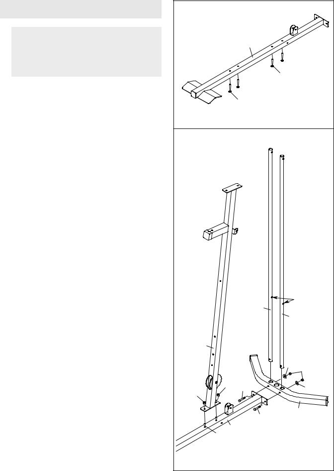
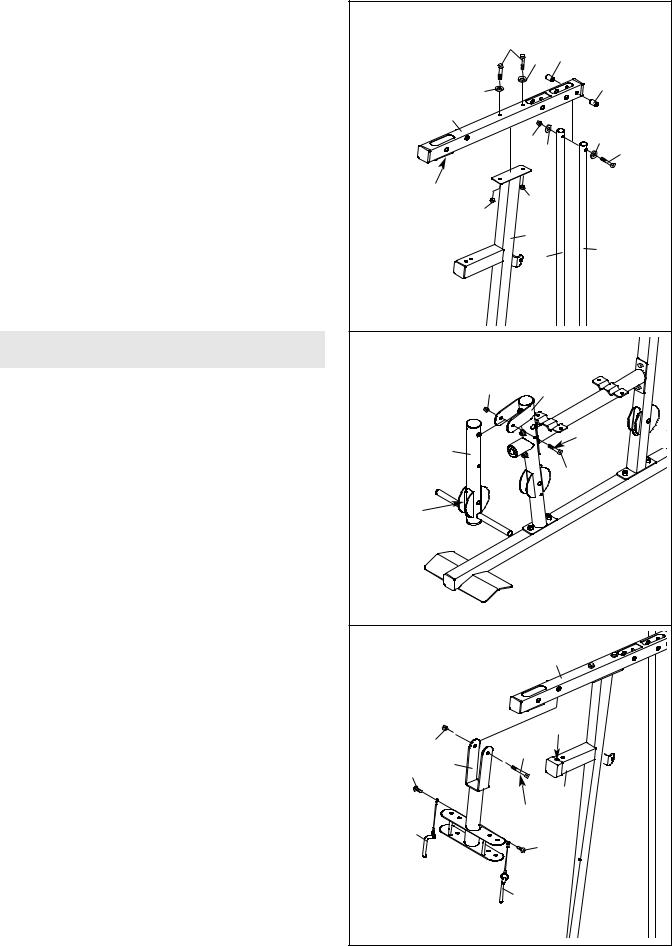
Frame Assembly |
1 |
|
|
|
|
|
|
|
|
|
|
|
|
|
1. |
Before beginning assembly, make sure you |
|
|
|
|
|
|
|
|
|
|
1 |
|
|
|
|
understand the information in the box on |
|
|
|
|
|
|
|
page 5. Refer to the PART IDENTIFICATION |
|
|
|
|
|
|
|
CHART in the center of this manual for help |
|
|
|
|
|
|
|
identifying small parts. |
|
|
|
|
64 |
|
|
Insert four M8 x 63mm Carriage Bolts (64) up |
|
|
|
|
|
|
|
|
|
|
|
|
|
|
|
through the Base (1). Note: It may be helpful to |
|
|
|
64 |
|
|
|
place a piece of tape over the bolt heads to |
|
|
|
|
|
|
|
hold them in place. |
|
|
|
|
|
|
2. Attach the Base (1) and the two Weight Guides |
2 |
|
|
|
|
|
|
|
(21) to the Stabilizer (2) with two M10 x 67mm |
|
|
|
|
|
|
|
|
|
|
|
|
|
|
|
Bolts (71), two M10 Washers (57), and two M10 |
|
|
|
|
|
|
|
Nylon Locknuts (56). Make sure the indicated |
|
|
|
|
|
|
|
holes in the Weight Guides are nearer the |
|
|
|
|
|
|
|
bottom. Fully tighten the Locknuts. |
|
|
|
|
|
|
|
Attach the Upright (3) to the Base (1) with the two |
|
|
|
|
|
|
|
indicated M8 x 63mm Carriage Bolts (64) and two |
|
|
|
|
|
|
|
M8 Nylon Locknuts (58). Do not tighten the |
|
|
|
|
|
|
|
Locknuts yet. |
|
|
|
|
|
|
|
|
|
|
|
21 |
|
Holes |
|
|
|
|
|
21 |
||
|
|
|
|
|
|
||
|
|
|
3 |
|
|
|
|
|
|
|
|
|
|
57 |
56 |
|
|
58 |
|
58 |
71 |
|
57 |
|
|
|
|
|
|
|
|
|
|
|
|
|
71 |
|
2 |
|
|
|
|
|
|
|
|
|
|
|
64 |
1 |
|
|
|
|
|
|
|
|
|
|
|
|
|
6 |
|
|
|
|
|
3. Attach the Front Leg (7) to the Base (1) with the |
3 |
|
|
|
|
|
|
|
|
two M8 x 63mm Carriage Bolts (64) and two M8 |
|
|
|
|
|
|
|
|
|
|
|
|
|
|
|
|
|
|
|
Nylon Locknuts (58). Do not tighten the |
|
|
|
|
|
7 |
|
|
|
Locknuts yet. |
|
|
|
33Up |
|
|
|
|
|
|
|
|
|
|
|
|
|
||
Attach the Leg Bumper (60) to the Front Leg (7) |
|
|
|
|
|
|
|
|
|
with an M4 x 20mm Self-tapping Screw (69) and |
|
|
|
|
60 |
58 |
|
|
|
an M4 Washer (33). Make sure the end of the |
|
|
|
69 |
|
|
|||
Bumper is pointing up. |
|
|
|
58 |
|
|
|
|
|
|
|
|
|
|
|
|
|
1 |
|
|
|
|
|
|
|
64 |
|
|
|
4. Attach the Seat Frame (6) to the Upright (3) with |
4 |
|
|
|
|
|
|
|
|
two M8 x 65mm Bolts (68), two M8 Washers (59), |
|
|
|
|
|
|
|
|
|
|
|
|
|
68 |
|
|
|
|
|
and two M8 Nylon Locknuts (58). Do not tighten |
|
|
|
|
|
|
|
|
|
the Locknuts yet. |
|
|
|
68 |
|
|
|
|
|
Attach the Seat Frame (6) to the Front Leg (7) |
|
|
|
|
|
|
59 |
58 |
|
|
|
|
|
|
|
|
|||
in the same manner. |
|
|
|
|
|
|
|
|
|
|
|
|
6 |
|
68 |
|
|
5958 |
|
|
|
|
|
68 |
|
|
|
||
|
|
|
59 |
|
|
3 |
|
|
|
|
|
|
|
7 |
|
|
|
||
|
|
|
|
|
|
|
|
||
|
|
58 |
|
59 |
|
|
|
|
|
|
|
|
|
|
|
|
|
|
|
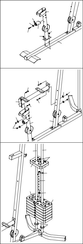
5. Slide the two Weight Bumpers (27) onto the |
5 |
|
|
|
|
|
|
|
|
Weight Guides (21). Orient the six Weights (22) |
|
|
21 |
|
21 |
|
|
|
|
|
|
|
|
|
|
|
|||
with the pin holes on the bottom as shown. Slide |
|
|
|
|
Grease |
|
|||
the Weights onto the Weight Guides. |
|
|
|
|
|
|
|||
Insert the Weight Tube Bumper (23) into the |
|
|
|
25 |
|
|
|
|
|
Weight Tube (24). Insert the Weight Tube into the |
|
|
|
|
Pin |
|
|
|
|
six Weights (22). Make sure the pin on the |
|
|
|
|
|
|
|
|
|
Weight Tube is oriented as shown. |
|
|
|
|
|
24 |
|
|
|
Lubricate the indicated holes in the Top Weight |
|
|
|
|
|
|
|
|
|
|
|
|
Pin |
|
|
|
|
|
|
(25) with the included grease packet. Slide the |
|
|
|
Hole |
|
23 |
|
|
|
Top Weight onto the Weight Guides (21). |
|
|
|
|
|
22 |
|
|
|
|
|
|
|
|
|
|
|
|
|
|
|
|
|
|
|
27 |
|
|
|
|
7 |
|
|
|
|
|
|
|
|
6. |
Orient the Top Frame (4) with the welded support |
6 |
|
|
|
|
|
|
|
|
on the bottom. |
|
|
|
|
|
|
|
|
|
|
|
|
|
68 |
|
|
|
|
|
Attach the Top Frame (4) to the Upright (3) with |
|
|
|
|
59 |
76 |
|
|
|
|
|
|
|
|
|
|||
|
two M8 x 65mm Bolts (68), two M8 Washers (59), |
|
|
|
|
|
|
76 |
|
|
and two M8 Nylon Locknuts (58). Do not tighten |
|
|
|
59 |
|
|
|
|
|
the Locknuts yet. |
|
|
4 |
|
|
|
|
|
|
|
|
|
|
|
|
|
||
|
Attach the Top Frame (4) between the Weight |
|
|
|
|
|
57 |
|
|
|
|
|
|
|
56 57 |
74 |
|||
|
Guides (21) with an M10 x 155mm Bolt (74), two |
|
|
|
|
|
|||
|
M10 Washers (57), two 19mm Spacers (76), and |
|
|
|
|
|
|
|
|
|
an M10 Nylon Locknut (56). |
Welded |
|
58 |
|
|
|||
|
Tighten the M8 Nylon Locknuts (58) used in |
Support |
58 |
|
|
||||
|
steps 2–6. |
|
|
|
|
3 |
21 |
|
|
|
|
|
|
|
|
|
21 |
|
|
|
|
|
|
|
|
|
|
|
|
|
Arm Assembly |
7 |
|
|
|
|
|
|
|
|
|
|
|
|
|
|
|
|
|
7. Grease an M10 x 77mm Bolt (79). Orient the Leg |
|
|
|
56 |
|
7 |
|
|
|
|
Lever (8) with the welded support on the side |
|
|
|
|
|
|
|
|
|
shown. Attach the Leg Lever to the Front Leg (7) |
|
|
8 |
|
|
|
Grease |
|
|
with the Bolt and an M10 Nylon Locknut (56). Do |
|
|
|
|
|
|
|
|
|
not overtighten the Locknut; the Leg Lever |
|
|
|
|
|
|
79 |
|
|
must be able to pivot easily. |
|
|
|
|
|
|
|
|
|
|
Welded |
|
|
|
|
|
|
|
|
|
Support |
|
|
|
|
|
|
|
8. |
Grease an M10 x 77mm Bolt (79). Attach the |
8 |
|
|
|
|
|
|
|
|
Pivot Frame (5) to the Top Frame (4) with the Bolt |
|
|
|
|
4 |
|
|
|
|
|
|
|
|
|
|
|
||
|
and an M10 Nylon Locknut (56). Do not over- |
|
|
|
|
|
|
|
|
|
tighten the Locknut; the Pivot Frame must be |
|
|
|
|
|
|
|
|
|
able to pivot easily. |
|
|
|
|
|
|
|
|
|
Attach the two Arm Pins (40) to the Pivot Frame |
|
56 |
|
|
79 |
Holes |
|
|
|
(5) with two M4 x 20mm Self-tapping Screws |
|
5 |
|
|
||||
|
(69). Insert the Arm Pins into the two holes in the |
69 |
|
|
|
|
|
|
|
|
Upright (3). |
|
|
|
|
|
|
|
|
|
|
|
|
|
|
|
3 |
|
|
|
|
40 |
|
|
|
Grease |
|
||
|
|
|
|
|
|
69 |
|
|
|
|
|
|
|
|
|
|
|
|
|
|
|
|
|
|
|
40 |
|
|
|
|
|
8 |
|
|
|
|
|
|
|
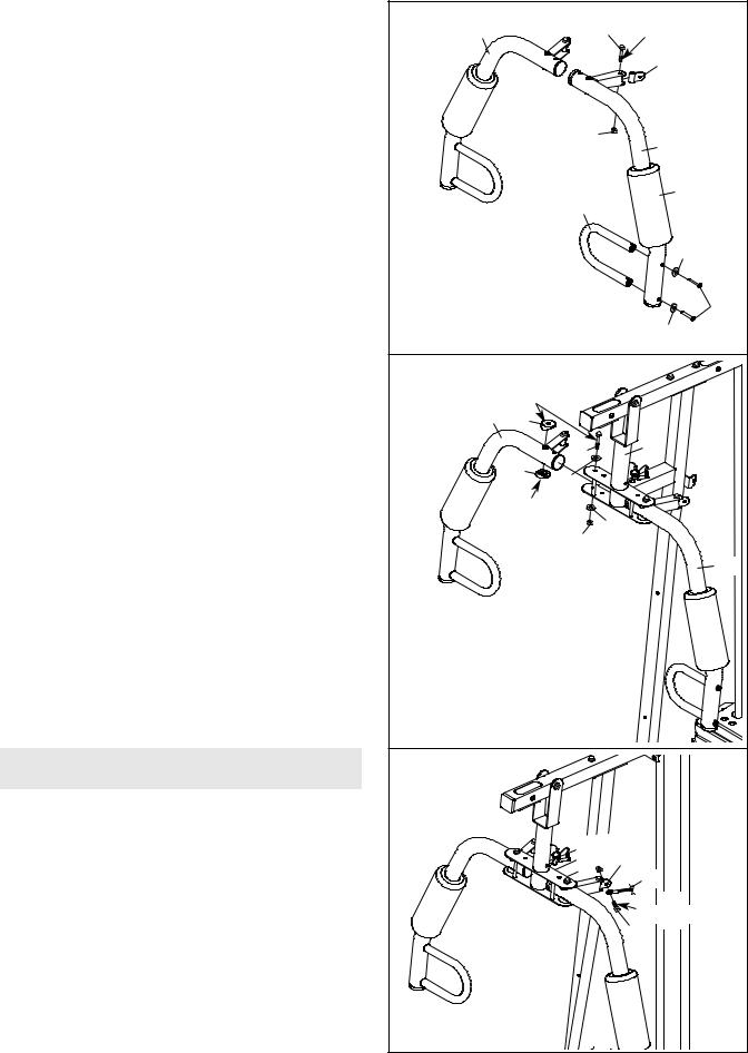
9. |
Grease an M10 x 51mm Bolt (66). Attach a Cable |
9 |
|
|
|
|
|
|
|
|
Pivot (39) to the Left Arm (10) with the Bolt and |
9 |
|
|
66 |
|
Grease |
|
|
|
|
|
|
|
|
||||
|
an M10 Nylon Locknut (56). Do not overtighten |
|
|
|
|
|
|
39 |
|
|
the Locknut; the Cable Pivot must be able to |
|
|
|
|
|
|
|
|
|
pivot easily. |
|
|
|
|
|
|
|
|
|
Wet the inside of a Large Foam Pad (42) with |
|
|
|
56 |
|
|
|
|
|
soapy water. Slide the Large Foam Pad onto the |
|
|
|
|
10 |
|
||
|
Left Arm (10). |
|
|
|
|
|
|
|
|
|
Attach a Handle (11) to the Left Arm (10) with two |
|
|
|
11 |
|
|
42 |
|
|
M10 x 25mm Button Bolts (77) and two M10 |
|
|
|
|
|
|
|
|
|
Washers (57). |
|
|
|
|
|
|
|
|
|
Assemble the Right Arm (9) in the same |
|
|
|
|
|
|
57 |
|
|
manner. |
|
|
|
|
|
|
|
|
|
|
|
|
|
|
|
|
57 |
77 |
|
|
|
|
|
|
|
|
|
|
10. |
Grease an M10 x 85mm Bolt (67) and two Arm |
10 |
|
|
|
|
|
|
|
|
Bushings (44). Attach the Right Arm (9) to the |
|
|
|
|
|
|
|
|
|
|
|
Grease |
|
|
|
|
|
|
|
Pivot Frame (5) with the Bolt, two M10 Washers |
|
9 |
|
|
|
|
|
|
|
(57), the two Arm Bushings, and an M10 Nylon |
|
44 |
|
|
|
|
|
|
|
Locknut (56). Do not overtighten the Locknut; |
|
|
|
67 |
|
|
5 |
|
|
the Arm must be able to pivot easily. |
|
|
44 |
|
|
|
||
|
Attach the Left Arm (10) to the Pivot Frame (5) |
|
|
57 |
|
|
|
|
|
|
|
|
Grease |
|
|
|
|
||
|
in the same manner. |
|
|
|
57 |
|
|
|
|
|
|
|
|
|
56 |
|
|
|
|
|
|
|
|
|
|
|
|
|
|
|
|
|
|
|
|
|
|
|
10 |
|
Cable Assembly |
11 |
|
|
|
|
|
|
|
|
|
|
|
|
|
|
|
|
|
11. |
Refer to the CABLE DIAGRAMS on page 19 as |
|
|
|
|
|
|
|
|
|
you assemble the cables and to identify the |
|
|
|
|
58 39 |
|
|
|
|
cables. |
|
|
|
|
54 |
|
||
|
Locate the Arm Cable (54). Grease an M8 x |
|
|
|
|
|
|
|
|
|
|
|
|
|
|
|
Grease |
|
|
|
22mm Shoulder Bolt (65). Attach the Cable to the |
|
|
|
|
|
|
|
|
|
indicated Cable Pivot (39) with the Bolt and an |
|
|
|
|
|
65 |
|
|
|
M8 Nylon Locknut (58). Make sure that the |
|
|
|
|
|
|
|
|
|
cable end can pivot easily on the shoulder |
|
|
|
|
|
|
|
|
|
bolt. |
|
|
|
|
|
|
|
|
|
|
9 |
|
|
|
|
|
|
|
 Loading...