

USB-CAN-B Manual
USB-CAN-B User Manual
www.waveshare.com 1 / 28 www.waveshare.com/wiki

USB-CAN-B Manual
CO NTENT
1. Product features ..............................................................................................................................3
1.1. Product Overview ..................................................................................................................... 3
1.2. Parameters .................................................................................................................................3
1.3. Typical applications .................................................................................................................. 4
2. Appearance and interface ............................................................................................................. 5
2.1. Appearance of the product ..................................................................................................... 5
2.2. Signal Definition ........................................................................................................................6
2.3. Factory configuration ...............................................................................................................6
3. Driver installation and USB-CAN-B tool ......................................................................................7
3.1. Driver installation ..................................................................................................................... 7
3.1.1 Win7 & win8& WIN10 & WIN11 system ............................................................7
3.1.2 Windows XP ...........................................................................................................13
3.2. USB-CAN-B tool software ......................................................................................................19
3.3. Software operation and Feat ures...................................................................................... 25
3.4 Self-Test .....................................................................................................................................27
3.5 Simultaneous use of multiple USB-CAN-B .......................................................................... 28
www.waveshare.com 2 / 28 www.waveshare.com/wiki

USB-CAN-B Manual
1. PR OD UC T FE AT U RE S
1. 1 . PROD U C T OVERVIE W
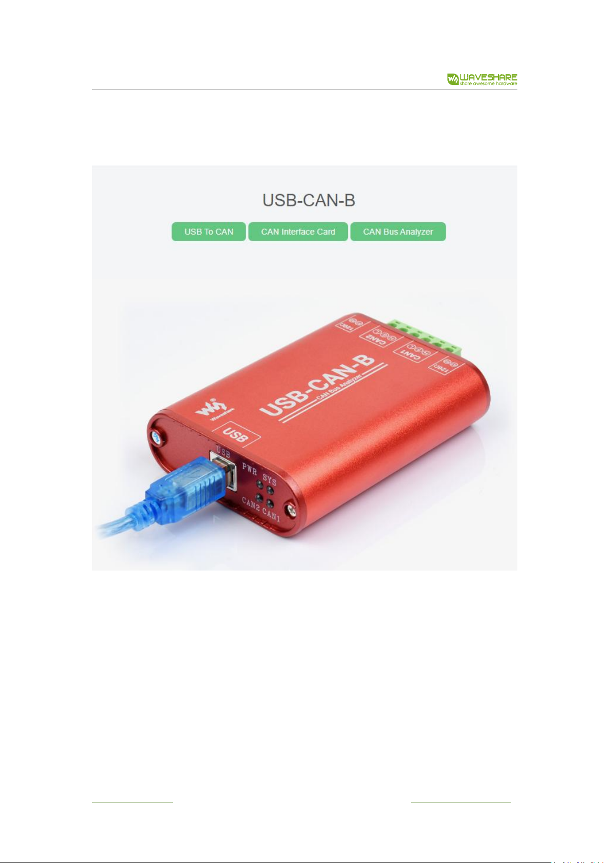
USB-CAN-B-2 (A / C) bus adapter is an intelligent CAN-bus adapter with USB2.0 interface and 2
CAN interface.
USB-CAN-B is a CAN-bus adapter with USB2.0 interface and 2 CAN interfaces and have CAN-bus
protocol analysis function that support SAE J1939, DeviceNet, CANopen, iCAN and customized
advanced protocol analysis function, also It is compatible with ZLG CANPro software and Can carry
out bidirectional transmission.
USB-CAN-B bus adapter/USB-CAN-B can be regarded as a standard CAN node, It is a powerful
tool for CAN-bus product development, CAN-bus equipment test and data analysis. Using this
interface adapter will enable PC to connect to standard CAN-bus network via USB interface, forming
the CAN-bus network control nodes for the data processing, data communication and data collection
applied in the CAN-bus networks such as bus laboratory, industrial control, intelligent residential zone,
auto electronics network, and etc. Meanwhile, small size, easy installation features of USB-CAN-B
Interface Adapter / USB-CAN-B makes it the best choice for the users who are using portable
operation systems.
There are three independent types of CAN-bus adapter:
USB-CAN-B-2A: CAN-bus is not isolated, powered directly by the USB.
USB-CAN-B-2C: CAN-bus circuit adopt Independent isolated DC - DC power supply module and
high-speed magnetic lotus root isolation module for electrical isolation, making the interface adapter
having strong anti-interference ability, greatly improved the reliability of the system used in harsh
environments. USB is isolated from CAN1 and CAN2, but CAN1 is not isolated from CAN2.
USB-CAN-B: USB, CAN1, CAN2 are completely isolated.
We can provide USB-CAN-B-Tool software to help you operating the USB-CAN-B adapter for
CAN-bus configuration, sending and receiving directly. We also provide a uniform application
programmable interface and the complete demonstration code including VC, VB, LabVIEW, Delphi
and C++ Builder, which make it convenient for user to develop programs.
You do not need to understand the complicated USB interface communication protocol when
you do your secondary software development with the USB-CAN-B bus interface adapter and
USB-CAN-B.
1. 2 . PAR AM ET E RS
Support protocol conversion between USB and CAN-bus;
USB-CAN-B-2(A/C) is dual-channel intelligent CAN interface module;
USB-CAN-B is dual-channel intelligent CAN interface module;
PC interface supports USB2.0 protocol and is Compatible with USB1.1;
www.waveshare.com 3 / 28 www.waveshare.com/wiki

USB-CAN-B Manual
Support CAN2.0A and CAN2.0B protocols, support standard frame and extension frame;
Support bi-directional transmission, CAN transmission and CAN receive;
Support data frame and remote frame;
CAN controller Baud rates from 10Kbps to 1Mbps, Can be configured by software;
USB-CAN-B-2A products: CAN-bus interface is not isolated;
USB-CAN-B-2C products: CAN-bus circuit adopt high-speed magnetic lotus root isolation and
Independent isolated DC - DC power supply module, USB is isolated from CAN1 and CAN2, CAN1 is
not isolated from CAN2.
USB-CAN-B: CAN-bus circuit adopts high-speed magnetic lotus root isolation and Independent
isolated DC - DC power supply module, USB, CAN1, CAN2 are completely isolated;
Max data flow: more than 8000 fps (standard frame) for receiving and 8000 fps (standard frame)
for transmitting and can be run at the same time;
Buffer size: 1000 frames length buffer for transmission (with auto repeat transmission when
failed) per channel, 2000 frames length buffer for receiving per channel;
Adopt USB bus power supply, no need for an external power supply;
USB-CAN-B-2A products: no electrical isolation;
USB-CAN-B-2C products: adopt electrical isolation, the isolation voltage is: 2500V;
USB-CAN-B, adopt electrical isolation, the isolation voltage is: 2500V;
Operating temperature: -20 ~ 85℃;
Physical size: (length) 70mm * (width) 45mm * (height) 24mm;
Product compatibility: Function library is similar to the library of Guangzhou ZLG USB-CAN-B
interface adapter.
1. 3 . TYPI C A L AP P L I CATIONS
Transmit or receive massages in CAN-bus network via PC or laptop's USB;
data collection, data analysis in the fast CAN network;
CAN-bus-USB gateway;
USB interface to CAN network interface;
Extend CAN-bus line length;
Industrial site CAN network data monitoring.
www.waveshare.com 4 / 28 www.waveshare.com/wiki
USB-CAN-B Manual
2. APPEA R A NCE AN D IN T E R FACE
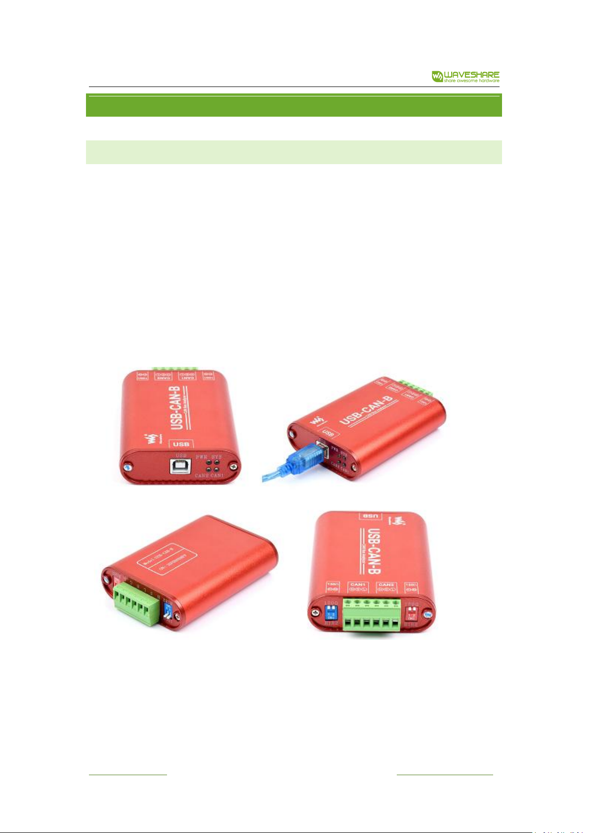
2. 1 . APPE A R ANCE OF THE PRODUCT
There are two sets of external interfaces on USB-CAN-B/ USB-CAN-B intelligent CAN interface
adapter: A standard USB interface, an 8-pin binding post terminals (USB-CAN-B for 6 pin), CAN-bus
interface is available.
Power indicator light of our products is red except USB-CAN-B for highlighted in red.
When LED- CAN1 Channel1 indicator light is red (USB-CAN-B for blue) indicate the transmitting or
receiving state of the channel1.When the USB-CAN-B adapter insert into a USB interface, the power is
turned on, the LED- CAN1 indicator light flashes twice for system self-test.
When LED- CAN2 Channel2 indicator light is red(USB-CAN-B for highlighted in red) indicate the
transmitting or receiving state of the channel 2.When the USB-CAN-B adapter insert into a USB
interface, the power is turned on, the LED- CAN2 indicator light flashes twice for system self-test.
www.waveshare.com 5 / 28 www.waveshare.com/wiki

USB-CAN-B Manual
Series of USB-CAN-B products
Name
Description
R+
Terminal resistance R+, R + and R- shorted, the internal 120
ohm resistor will be access to the bus
R-
Terminal resistance R-
CANH
CAN_H signal cable
CANL
CAN_L signal cable
PWR
Power indicator light
CAN1
CAN1 channel signal
CAN2
CAN2 channel signal
USB-CAN-B products
Name
Description
R1
Terminal resistance R1, Down to the ON state, the internal 120
ohm resistor will be access to the bus.
R2
Terminal resistance R2, in parallel with R1, same effect as R1
H
CAN_H signal cable
S
Shielded wire interface, unconnected with the CAN transceiver
directly, connected with resistors and capacitors.
L
CAN_L signal cable
PWR
Power indicator light
SYS
System status indication, under normal circumstances are
often off state
CAN1
CAN1 channel signal
CAN2
CAN2 channel signal
2. 2 . SIGNA L DEFINITIO N
Method of operation:
CAN Transmit: When a user application calls the Transmit Function, a message will be push to
the channel T-Buffer (it’s a FIFO buffer) in USB-CAN-B adapter immediately, then the CAN Controller
transmit it to the CAN-Bus.
CAN Receive: The CAN Controller receives a CAN frame from CAN-Bus, and push it to the channel
R-Buffer (also a FIFO buffer) in USB-CAN-B adapter immediately, when a user application call the
Receive-Function, the message will be return.
2. 3 . FACT O R Y CO N F IG URATION
1) CAN-bus Baud rate: 1Mbps;
2) Acceptance mask register: 0xFFFFFFFF, means to accept all CAN frame;
3) Termination resistor is selectable: connect the R+ and R- (dial down the corresponding switch
www.waveshare.com 6 / 28 www.waveshare.com/wiki
USB-CAN-B Manual
for USB-CAN-B) to get 120 euro internal resistor.
Note: ensure that there are two 120 ohm termination resistors on the CAN-bus; otherwise it will
lead to the CAN-bus work abnormality.
The above description is effective for each CAN channel.
3. DR I VER INSTALL A T IO N AN D USB-CAN - B TO O L
3. 1 . DRIV E R INSTALLA T I ON
3. 1 .1 WI N 7 & WI N8 & W I N 10 & WIN11 SY ST EM
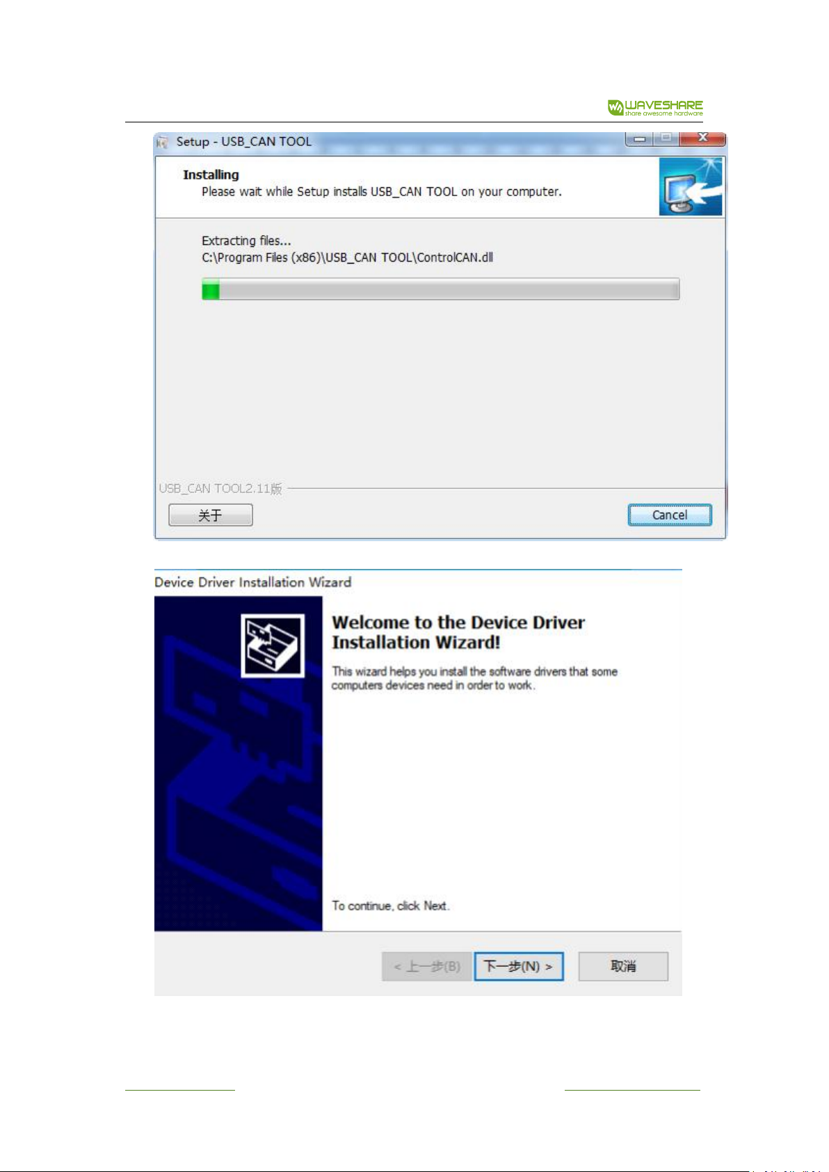
Connect USB-CAN-B intelligent interface module to the PC with USB cable correctly. The
Windows will then auto run an installation wizard called “new hardware is found” after the hardware
is detected. Select “Install the software automatically (Recommended)”.
Click “Next” to continue;
www.waveshare.com 7 / 28 www.waveshare.com/wiki

USB-CAN-B Manual
www.waveshare.com 8 / 28 www.waveshare.com/wiki

USB-CAN-B Manual
If the windows 7 do not run the wizard, Right click "My Computer" and select "Device Manager"
and find the “other devices” in other devices list:
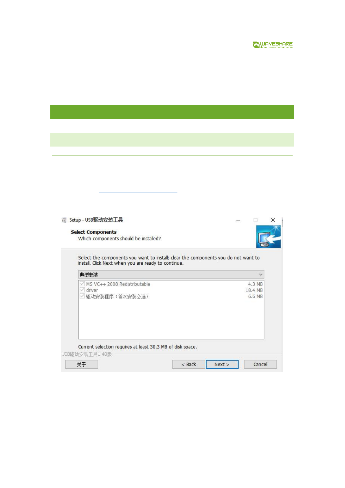
Right-click “unknown device”, select “update driver software”, manually add the driver of the
device. Select the driver for installation from directory as showed in diagram below. Then it will
prompt a message said whether to confirm the installation, click confirm to go.
www.waveshare.com 9 / 28 www.waveshare.com/wiki

USB-CAN-B Manual
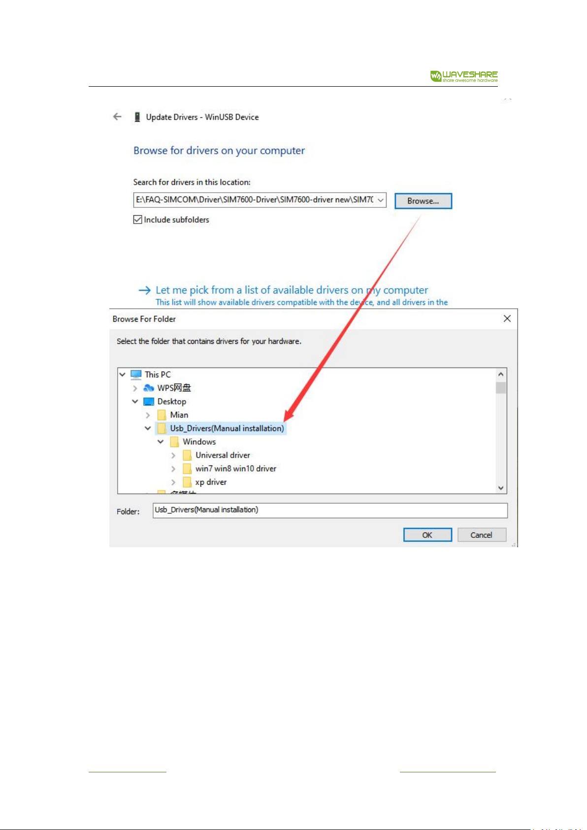
Select “Browse the computer to find the driver software” and click next.
Select directory and install (driver located in the directory of directory [hardware drivers]). Select
directory and install Usb_Drivers(Manual installation) in the directory of [hardware drivers]. Use the
“Browse for Folder” window selects where the driver is:
www.waveshare.com 10 / 28 www.waveshare.com/wiki
USB-CAN-B Manual
In some cases, the system will prompt a message that the WinUSBCoInstaller2.dll cannot be
found. Then, click "Browse", and select the WinUSBCoInstaller2.dll file from the i386 (for 32 bit
system) or AMD64 (for 64 bit systems) folder in the directory of drive program directory
"USB-CAN-B".
www.waveshare.com 11 / 28 www.waveshare.com/wiki

USB-CAN-B Manual
If installed "USB_CAN TOOL Setup. exe", the corresponding USB drive will generate in the
software installation directory, so can also install the driver from the file of corresponding USB drive.
After installation, "USB-CAN-B or USB_CAN Device" will be added to the directory of device
manager.
www.waveshare.com 12 / 28 www.waveshare.com/wiki

USB-CAN-B Manual
After installation, "WinUSB Device" will be added to the directory of device manager.
If installed "USB_CAN TOOL Setup. Exe", the corresponding USB drive will generate in the
software installation directory, so can also install the driver from the file of corresponding USB drive.
3. 1 .2 WIND O W S X P
Connect USB-CAN-B intelligent interface module to the PC with USB cable correctly.
The Windows will then auto run an installation wizard called “new hardware is found” after the
hardware is detected. Select “Install the software automatically (Recommended)”.
Click “Next” to continue;
www.waveshare.com 13 / 28 www.waveshare.com/wiki

USB-CAN-B Manual
If the windows XP do not run the wizard, Right click "My Computer" and select "Device Manager"
and find the “other devices” in other devices list:
Right click “Unknown device”, and select “Update Driver” from the menu:
Select “Install from a list or specific location (Advanced)” .Click “Next” to continue:
www.waveshare.com 14 / 28 www.waveshare.com/wiki
USB-CAN-B Manual
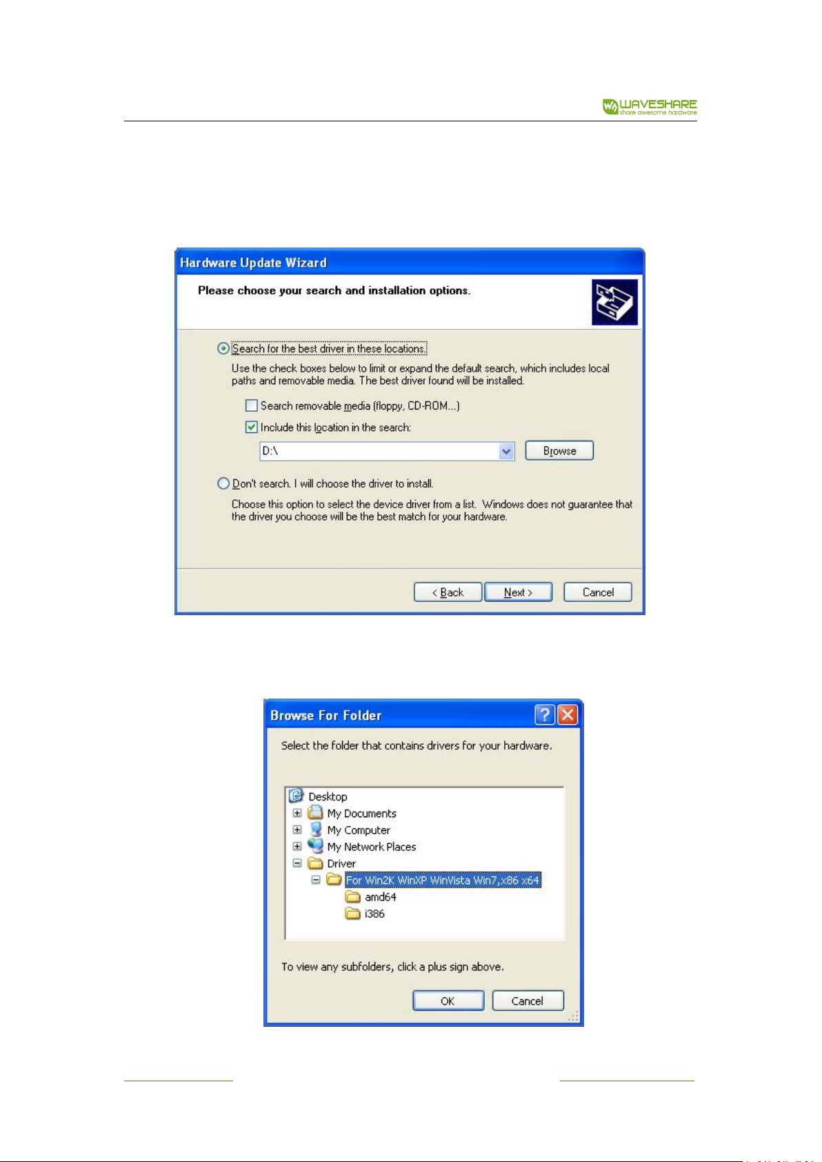
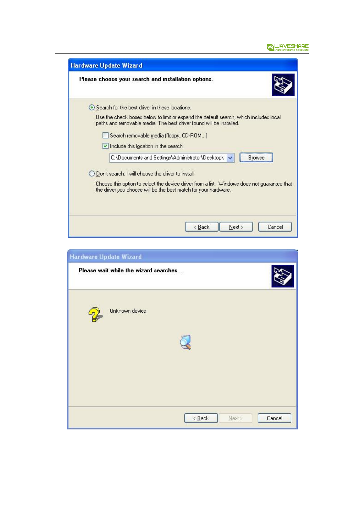
Next, select “Search for the best driver in these locations”, and check “Include this location in the
search:”(do not select “Search removable media otherwise it is possible to come with an exclamation
point or tips after successfully installed the driver and reboot the corresponding device in Device
Manager which causing the device unusable.). Then click “Browse” button to browse the driver folder:
Select directory and install (driver located in the directory of directory [hardware drivers]).
Select directory and install “USB-CAN-B” (Depending on the model) in the directory of [hardware
drivers]. Use the “Browse for Folder” window selects where the driver is:
Click “OK” to finish selection:
www.waveshare.com 15 / 28 www.waveshare.com/wiki
USB-CAN-B Manual
Click “Next” to search and install driver:
www.waveshare.com 16 / 28 www.waveshare.com/wiki
USB-CAN-B Manual
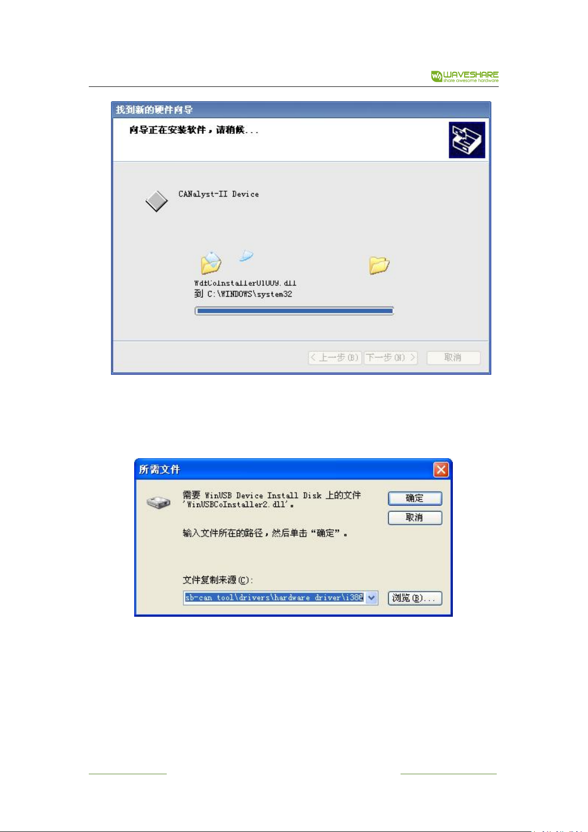
In some cases, the system will prompt a message that the WinUSBCoInstaller2.dll cannot be
found. Then, click "Browse", and select the WinUSBCoInstaller2.dll file from the i386 (for 32 bit
system) or AMD64 (for 64 bit systems) folder in the directory of drive program directory
"USB-CAN-B".
www.waveshare.com 17 / 28 www.waveshare.com/wiki
USB-CAN-B Manual
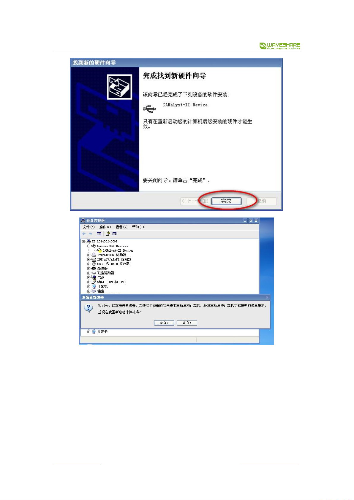
When the system suggest to restart, or an exclamation point on a model in the device manager
appear, please restart the system.
After installation, "USB-CAN-B or USB_CAN Device" will be added to the directory of device
manager.
If installed "USB_CAN TOOL Setup. Exe", the corresponding USB drive will generate
in the software installation directory, so can also install the driver from the file of corresponding
USB drive.
www.waveshare.com 18 / 28 www.waveshare.com/wiki
USB-CAN-B Manual
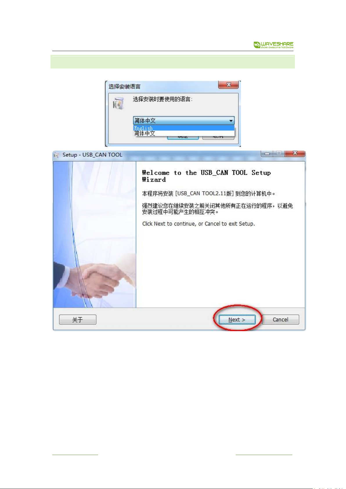
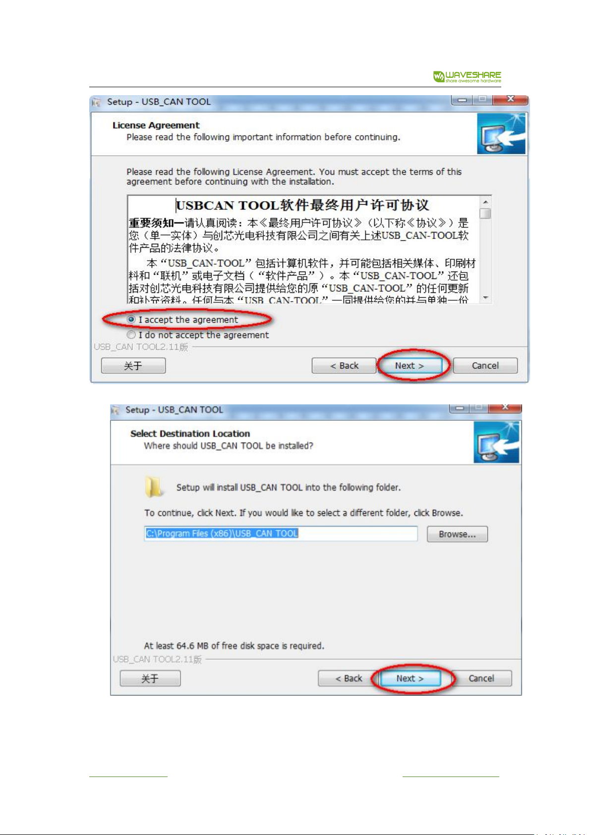
3. 2 . USB- C A N -B TO O L S O F TW AR E
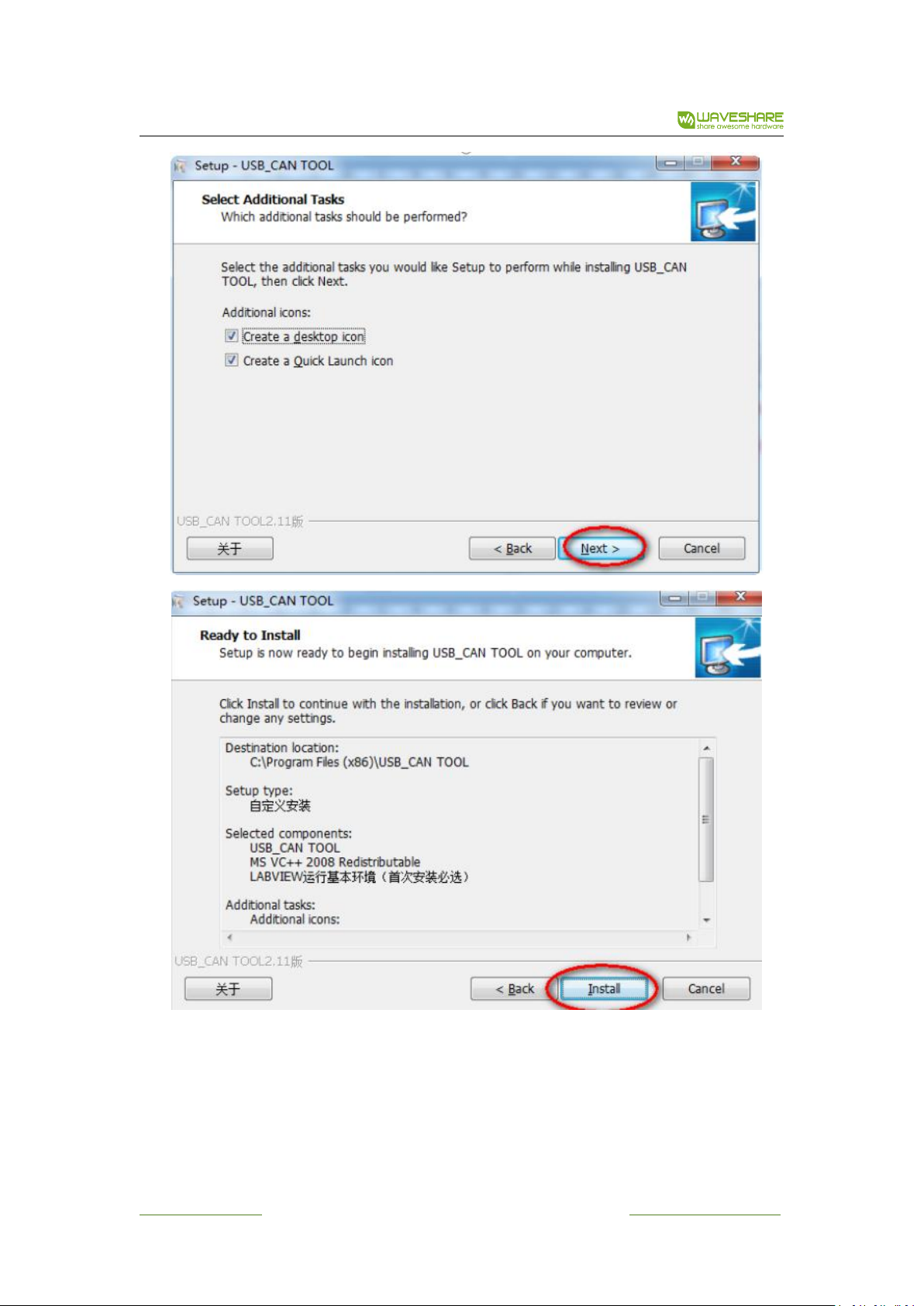
Run and install USB-CAN-B TOOL Setup.exe
www.waveshare.com 19 / 28 www.waveshare.com/wiki
USB-CAN-B Manual
www.waveshare.com 20 / 28 www.waveshare.com/wiki
USB-CAN-B Manual
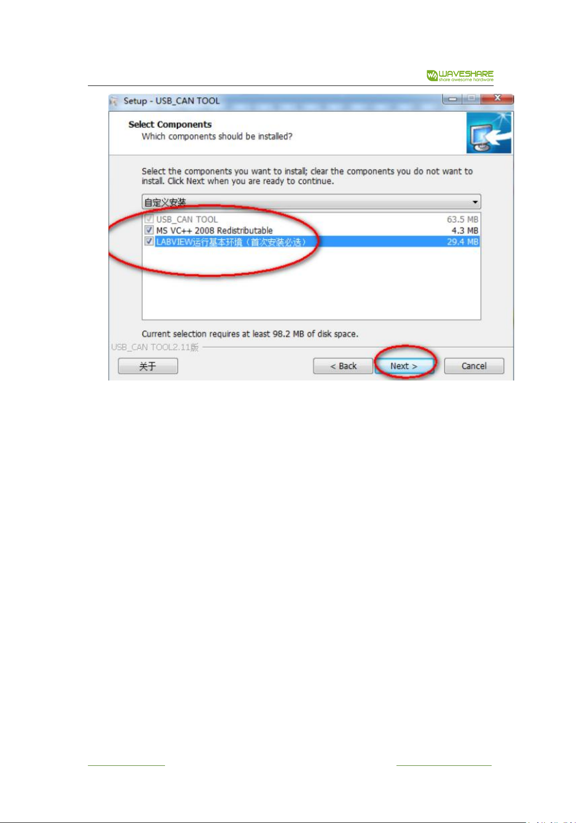
First time to install the USB-CAN-B please make sure to check “run Engine” .this
installation package is needed for the application developed from the LABVIEW
environment.
First time to install the USB-CAN-B please make sure to check “run Engine” .this installation
package is needed for the application developed from the LABVIEW environment.
www.waveshare.com 21 / 28 www.waveshare.com/wiki
USB-CAN-B Manual
www.waveshare.com 22 / 28 www.waveshare.com/wiki
USB-CAN-B Manual
www.waveshare.com 23 / 28 www.waveshare.com/wiki
USB-CAN-B Manual
If you need termination resistor, connect R+ with R-.
Note: must ensure that there are two 120 ohm termination resistors connected to the bus,
otherwise it will cause CAN-bus work abnormality.
Connect the USB interface of the device with PC via USB.
www.waveshare.com 24 / 28 www.waveshare.com/wiki

USB-CAN-B Manual
Run “USB-CAN-B Tool.exe” as shown in the following figure:
3. 3 . SOF TW A R E O P E R ATION AND FEAT URES
Select Device
If use USB-CAN-B-2(A/C) or USB-CAN-B product, select menu “Select Device”-> “USB-CAN-B”(the
default option).
Start/Stop Device
Select menu “Device Operation”-> “Start”, to open specified channel, USB-CAN-B Tool forced to
start all channels.
Select menu “Device Operation”-> “Stop”, to close all running channels.
www.waveshare.com 25 / 28 www.waveshare.com/wiki

USB-CAN-B Manual
Registers
Select menu “Device Operation”-> “Registers”, to view the registers’ information (compatible the
ZLG mode).
Current configuration
Select menu “Information”-> “ParamNow”, to view the current configuration.
Device Information
Select menu “Information”-> “Device Information”, to view the device information such as
product model, serial number, version number, etc.
Select Channel
USB-CAN-B-2(A/C) product have two channels, the index number is respectively 0, 1 (Ch1, Ch2).
Set CAN parameters to ensure that the setting is correct for each channel.
CAN Baud Rate
Select menu “Settings” -> “CAN Settings”, to modify the value into your needs
If connected with external devices, please must make sure baud rate is same to the external
devices then click "Set", there is a message when success.
Note: We recommend that you first set baud rate, then connect it to CAN-bus.
Work mode
USB CAN products support 3 kind of work-mode: normal, listen, self-Test (loopback). Normal:
The CAN module will appear on the CAN-bus, and it can send and receive
CAN messages.
Listen: The module will appear on the CAN-bus, but in a passive state. It can receive CAN
messages, but cannot transmit CAN messages or answer. This mode can be used as a bus monitor
because it does not affect CAN-bus communications but can observe the CAN-bus states.
Self-Test (loopback): For adapter self-test, CAN module receives its own messages. In this mode,
the send part of the CAN module is connected internally with the reception one. This mode will
provide a "false" response, so that don’t need another node to provide the acknowledge bit. And the
CAN messages will not sent to CAN-bus.
Filter
Users can set the filter-mode, ACR and AMR to filter the received CAN messages.
Note: please refer to "9.annex 2:CAN description parameter setting”for further information.
Transmit messages
When transmit messages, need to select extend frame/standard frame, a remote frame/data
frame, frame ID, data length, data and other information.
Please enter 16 hexadecimal format values In the CAN test software ID edit box and data edit
box, and each value need space. When sending ID up from the top 4 values, data up to the first 8
values.
Note: The “System time” in data list is system time in computer, and compare with the actual
eventuate-time there may be up to 50ms difference.
Attention: The USB-CAN-B products will not receive acknowledge message when it isn’t connect
to the CAN-bus or parameters settings error , then it will resend the messages automatic until the
message is received by other node in CAN-bus or the USB-CAN-B product restart. There is 1000
frames length send buffer, it will return 0 when call the “VCI_transmit” function failure.
www.waveshare.com 26 / 28 www.waveshare.com/wiki

USB-CAN-B Manual
ID Format
There are two kind of format for ID format: SJA1000 mode (Align Left) and Real ID (Align Right).
SJA1000 mode:SJA1000 internal registers format, the highest bit of the ID and ID byte Bit31
alignment. For example, standard frame ID = 2, make 0x00 00 00 02 shift left 21 bit, and the SJA1000
mode ID is 0x 00 40 00 00; if the frame is extended one, make 0x00 00 00 02 shift left 3 bit, then the
SJA1000 mode ID is 0x00 00 00 10(temporary invalid).
Real ID: The lowest bit (Bit0) of ID is aligned with the ID byte Bit0.For example, if ID = 2, then file
00 00 00 02 in the ID edit box directly. This format is simple and intuitive.
Each time the data will be displayed in the list box on the interface.
Enable/Disable Receive
Check “CAN receive enable” to open the receive thread. The latest messages will be shown in list
control in time. If uncheck “CAN receive enable”, when there are messages on CAN-bus, the receive
buffer on the USB-CAN-B adapter may overflow.
When in the high-speed receiving, it is best not operating the CAN settings, query etc. Open the
CAN bus receiver function, when check receiving box in the main interface,receiving function is
opened at the same time.
If the data received from the other CAN node will be displayed on the interface.
High-speed mode, show list data, information save
These three items are located in “Display” menu.
When the “High-speed mode” is checked, “show list data” and “information saves” become
invalid.
When the “”show list data” is checked, the latest messages will be shown in list control make
CAN message monitoring more in time.
When the “information save” is checked, the messages will be save to the specified text-format
excel-file for a long time.
We recommend that you check the "high-speed mode" in order to save memory and CPU
consumption when using the high-speed transceiver.
3. 4 SELF-TES T
Each channel supports self-test mode.
Do Self-test in the following steps:
1)Plug the USB-CAN-B adapter into the PC's USB, and then run the “USB-CAN-B Tool”.
2)Select menu “Select Device” “USB-CAN-B 2.0”, then select menu “Device Operation”
“Start” to open the USB-CAN-B adapter, and set the “work mode” to “self-test” in next popup dialog.
3)In the main UI Send area, set “Frames=1”, “Send Interval=1000”, check “CAN receive enable”,
then, click “send” button to send message. It will receive the same message in same channel.
If there is no problem in the receiving function test shows that the USB - CAN adapter no fault in
the work.
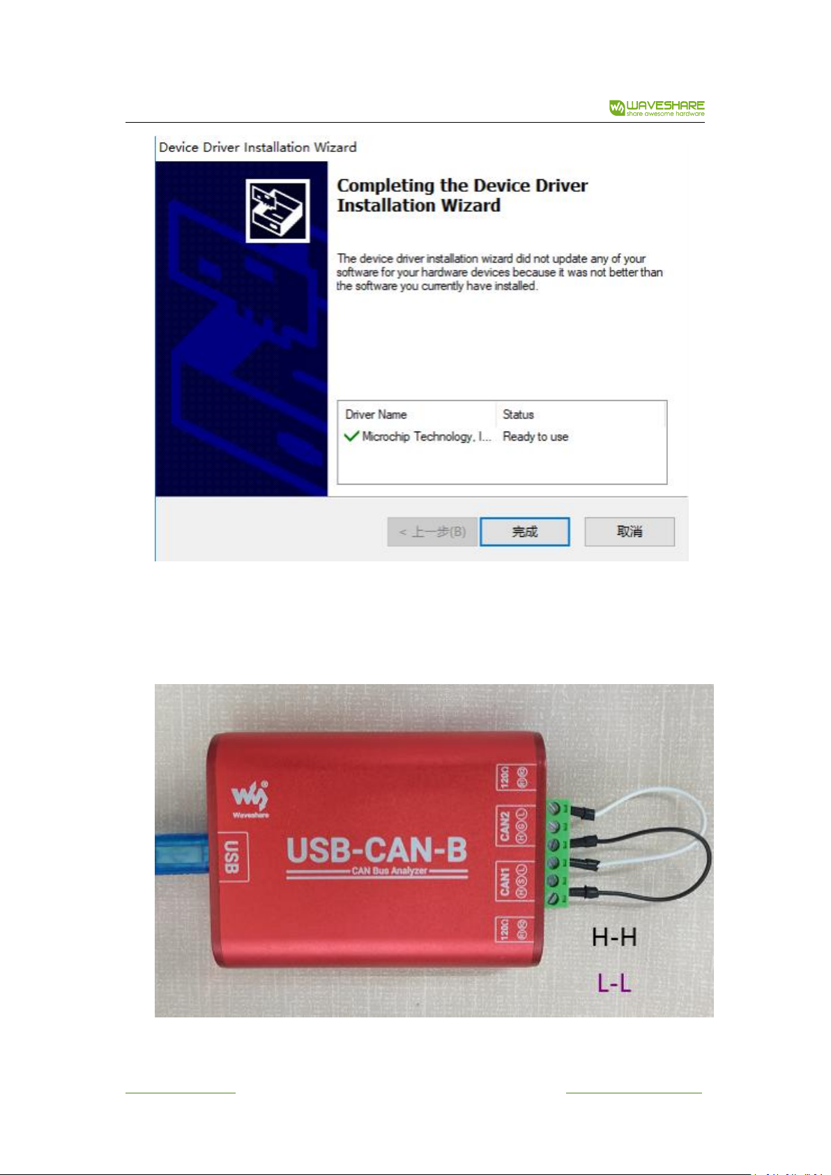
USB - CAN - 2 (A/C), USB-CAN-B has dual channel CAN interfaces, you also can interconnect
channel1 and cchannel2 to test. This test is more comprehensive, and can direct response CAN
transceiver failure, please refer to the ”USB - CAN bus adapter testdocumentation“for more detail.
www.waveshare.com 27 / 28 www.waveshare.com/wiki

USB-CAN-B Manual
Tips:
If the above operation is not success, please check the correct steps carefully. If it still does not
work, please contact us.
If it can’t receive messages after the USB-CAN-B adapter restart, may need to restart
the USB-CAN-B Tool.
When using the adapter for external CAN equipment debugging, please put the USB- CAN CANH,
CANL corresponding connected with CANH, CANL of external CAN devices, other line do not need to
connect.
3. 5 SIMULTA N E O US USE OF MU LTIPLE USB-C A N - B
USB-CAN-B Tool supports the same computer to connect up to four USB-CAN-B modules at the
same time. Please refer to “multiple cards operation at the same time instruction handbook” for
More details.
Note: more detailed information about USB - CAN tool, please refer to “ the USB -
CAN tool instructions”.
www.waveshare.com 28 / 28 www.waveshare.com/wiki
 Loading...