


 Loading...
Magnum Cv and Magnum IT Valves
Installation and Service Manual


Table of Contents
Section
1.0 |
Installation Profile Summary |
- |
- |
- |
- |
- |
- |
- |
- |
- |
- |
- |
- |
- |
- |
- |
- |
- |
- |
- |
- |
- |
- |
- |
- |
- |
- |
- 1 |
||||
2.0 |
Introduction to the Magnum Cv and Magnum IT Series - |
- |
- |
- |
- |
- |
- |
- |
- |
- |
- |
- |
- |
- |
- 2 |
|||||||||||||||||
|
2.1 |
Assembling the Control to the Valve |
- |
- |
- |
- |
- |
- |
- |
- |
- |
- |
- |
- |
- |
- |
- |
- |
- |
- |
- |
- 3 |
||||||||||
|
2.2 |
General Specifications |
- |
- |
- |
- |
- |
- |
- |
- |
- |
- |
- |
- |
- |
- |
- |
- |
- |
- |
- |
- |
- |
- |
- |
- |
- |
- 7 |
||||
|
2.3 |
Dimensional Specifications |
- |
- |
- |
- |
- |
- |
- |
- |
- |
- |
- |
- |
- |
- |
- |
- |
- |
- |
- |
- |
- |
- |
- |
- 8 |
||||||
3.0 |
General Installation Information - |
- |
- |
- |
- |
- |
- |
- |
- |
- |
- |
- |
- |
- |
- |
- |
- |
- |
- |
- |
- |
- |
- |
- |
- |
10 |
||||||
|
3.1 |
Typical Installation Drawings - |
- |
- |
- |
- |
- |
- |
- |
- |
- |
- |
- |
- |
- |
- |
- |
- |
- |
- |
- |
- |
- |
- |
12 |
|||||||
4.0 |
Flow Diagrams |
- - - - - |
- |
- |
- |
- |
- |
- |
- |
- |
- |
- |
- |
- |
- |
- |
- |
- |
- |
- |
- |
- |
- |
- |
- |
- |
- |
- |
- |
13 |
||
5.0 Control Settings - - - - - |
- |
- |
- |
- |
- |
- |
- |
- |
- |
- |
- |
- |
- |
- |
- |
- |
- |
- |
- |
- |
- |
- |
- |
- |
- |
- |
- |
19 |
||||
|
5.1 |
Manual Control - |
- |
- |
- |
- |
- |
- |
- |
- |
- |
- |
- |
- |
- |
- |
- |
- |
- |
- |
- |
- |
- |
- |
- |
- |
- |
- |
- |
- |
19 |
|
|
5.2 |
Mechanical Control |
- |
- |
- |
- |
- |
- |
- |
- |
- |
- |
- |
- |
- |
- |
- |
- |
- |
- |
- |
- |
- |
- |
- |
- |
- |
- |
- |
24 |
||
|
|
5.2.1 Common Settings - - - - - - - - |
- |
- |
- |
- |
- |
- |
- |
- |
- |
- |
- |
- |
- |
- |
- |
24 |
||||||||||||||
|
|
5.2.2 Regenerating Iron Filter - - - - - - - - |
- |
- |
- |
- |
- |
- |
- |
- |
- |
- |
- |
- |
- |
25 |
||||||||||||||||
|
|
5.2.3 Backwashing Filter - - - - - - - - - |
- |
- |
- |
- |
- |
- |
- |
- |
- |
- |
- |
- |
- |
- |
25 |
|||||||||||||||
|
|
5.2.4 Salt Use Table - - - - - - - - - |
- |
- |
- |
- |
- |
- |
- |
- |
- |
- |
- |
- |
- |
- |
- |
- |
26 |
|||||||||||||
|
|
5.2.5 |
Potassium Permanganate Use Table- |
- |
- |
- |
- |
- |
- |
- |
- |
- |
- |
- |
- |
- |
- |
27 |
||||||||||||||
|
5.3 |
Impulse Controls |
- |
- |
- |
- |
- |
- |
- |
- |
- |
- |
- |
- |
- |
- |
- |
- |
- |
- |
- |
- |
- |
- |
- |
- |
- |
- |
- |
- |
28 |
|
|
5.4 |
Electronic Controls- - - - - - - - - - |
- |
- |
- |
- |
- |
- |
- |
- |
- |
- |
- |
- |
- |
- |
- |
- |
- |
- |
29 |
|||||||||||
|
|
5.4.1 Connecting the 962 Control- - - - - - - - - |
- |
- |
- |
- |
- |
- |
- |
- |
- |
- |
31 |
|||||||||||||||||||
|
|
5.4.2 |
Connecting the 962M and the 962S |
Control - |
- |
- |
- |
- |
- |
- |
- |
- |
- |
- |
32 |
|||||||||||||||||
|
|
5.4.3 |
Connecting the 962 Twin and Triple Parallel Control- |
- |
- |
- |
- |
- |
- |
- |
33 |
|||||||||||||||||||||
6.0 |
Programming Tables for Electronic Controls - |
- |
- |
- |
- |
- |
- |
- |
- |
- |
- |
- |
- |
- |
- |
- |
- |
- |
- |
34 |
||||||||||||
|
6.1 |
Table I - Level I Values - |
- |
- |
- |
- |
- |
- |
- |
- |
- |
- |
- |
- |
- |
- |
- |
- |
- |
- |
- |
- |
- |
- |
- |
- |
- |
34 |
||||
|
6.2 |
Table IIA - Level II Program Values 962 Single Twin or Triple Parallel |
|
|
|
|
|
|
||||||||||||||||||||||||
|
|
Tank Softener or Dealkalizer - |
- |
- |
- |
- |
- |
- |
- |
- |
- |
- |
- |
- |
- |
- |
- |
- |
- |
- |
- |
- |
- |
- |
35 |
|||||||
|
6.3 |
Table IIB - Level II Program Values 962F |
|
|
|
|
|
|
|
|
|
|
|
|
|
|
|
|
|
|
||||||||||||
|
|
Single Tank Filter Mode Parameters |
- |
- |
- |
- |
- |
- |
- |
- |
- |
- |
- |
- |
- |
- |
- |
- |
- |
- |
- |
36 |
||||||||||
|
6.4 |
Table IIC - Level II Program Values 962 Twin Tank Alternating |
|
|
|
|
|
|
|
|
|
|||||||||||||||||||||
|
|
Softener - - - - - - - - - - |
- |
- |
- |
- |
- |
- |
- |
- |
- |
- |
- |
- |
- |
- |
- |
- |
- |
- |
- |
- |
- |
- |
37 |
|||||||
|
6.5 |
Table IID - Level II Program Values - Electronic Timeclock |
|
|
|
|
|
|
|
|
|
|
||||||||||||||||||||
|
|
Filter - |
- - - - - |
- |
- |
- |
- |
- |
- |
- |
- |
- |
- |
- |
- |
- |
- |
- |
- |
- |
- |
- |
- |
- |
- |
- |
- |
- |
- |
- |
38 |
|
|
6.6 |
Table IIE - Level II Program Values - Electronic Timeclock |
|
|
|
|
|
|
|
|
|
|
||||||||||||||||||||
|
|
Softener |
- - - |
- |
- |
- |
- |
- |
- |
- |
- |
- |
- |
- |
- |
- |
- |
- |
- |
- |
- |
- |
- |
- |
- |
- |
- |
- |
- |
- |
- |
39 |
|
6.7 |
Explanation of Parameter Values for the 962 Single and Parallel |
|
|
|
|
|
|
|
|
||||||||||||||||||||||
|
Tank Controls - - - - - - |
- |
- |
- |
- |
- |
- |
- |
- |
- |
- |
- |
- |
- |
- |
- |
- |
- |
- |
- |
- |
- |
- |
- |
- |
- |
- |
40 |
||||
|
6.8 |
New Features in the 962 Family Controls - |
- |
- |
- |
- |
- |
- |
- |
- |
- |
- |
- |
- |
- |
- |
- |
- |
42 |
|||||||||||||
|
6.9 |
Table III Historical Data |
- |
- |
- |
- |
- |
- |
- |
- |
- |
- |
- |
- |
- |
- |
- |
- |
- |
- |
- |
- |
- |
- |
- |
- |
- |
43 |
||||
|
6.10 Table IV Error Messages |
- |
- |
- |
- |
- |
- |
- |
- |
- |
- |
- |
- |
- |
- |
- |
- |
- |
- |
- |
- |
- |
- |
- |
- |
44 |
||||||

7.0 |
Multi-Tank Systems |
- |
- |
- |
- |
- |
- |
- |
- |
- |
- |
- |
- |
- |
- |
- |
- |
- |
- |
- |
- |
- |
- |
- |
- |
- |
- |
- |
- |
- |
- |
45 |
|
|
7.1 |
Twin Alternating - - - - |
- - |
- |
- |
- |
- |
- |
- |
- |
- |
- |
- |
- |
- |
- |
- |
- |
- |
- |
- |
- |
- |
- |
- |
- |
45 |
||||||
|
|
7.1.1 Control Set-up - |
- |
- |
- |
- |
- - - - |
- |
- |
- |
- |
- |
- |
- |
- |
- |
- |
- |
- |
- |
- |
- |
- |
46 |
|||||||||
|
|
7.1.2 Additional Checks |
- |
- |
- |
- |
- |
- |
- |
- |
- |
- |
- |
- |
- |
- |
- |
- |
- |
- |
- |
- |
- |
- |
- |
47 |
|||||||
|
7.2 |
Twin and Triple Parallel |
- |
- |
- |
- |
- |
- |
- |
- |
- |
- |
- |
- |
- |
- |
- |
- |
- |
- |
- |
- |
- |
- |
- |
- |
- |
48 |
|||||
|
|
7.2.1 Control Set-up |
- |
- |
- |
- |
- |
- |
- |
- |
- |
- |
- |
- |
- |
- |
- |
- |
- |
- |
- |
- |
- |
- |
- |
- |
- |
50 |
|||||
8.0 |
Start-Up Procedure |
- |
- |
- |
- |
- |
- |
- |
- |
- |
- |
- |
- |
- |
- |
- |
- |
- |
- |
- |
- |
- |
- |
- |
- |
- |
- |
- |
- |
- |
- |
51 |
|
9.0 |
Service Instructions |
- |
- |
- |
- |
- |
- |
- |
- |
- |
- |
- |
- |
- |
- |
- |
- |
- |
- |
- |
- |
- |
- |
- |
- |
- |
- |
- |
- |
- |
- |
52 |
|
|
9.1 |
Magnum Valve Cartridge Removal Procedure - |
- |
- |
- |
- |
- |
- |
- |
- |
- |
- |
- |
- |
- |
- |
54 |
||||||||||||||||
10.0 |
Performance Data |
- |
- |
- |
- |
- |
- |
- |
- |
- |
- |
- |
- |
- |
- |
- |
- |
- |
- |
- |
- |
- |
- |
- |
- |
- |
- |
- |
- |
- |
- |
55 |
|
|
10.1 |
Injector Data- - - - - - - |
- |
- |
- |
- |
- |
- |
- |
- |
- |
- |
- |
- |
- |
- |
- |
- |
- |
- |
- |
- |
- |
- |
- |
55 |
|||||||
|
10.2 |
Refill Control Chart (P6 Values) |
- |
- |
- |
- |
- |
- |
- |
- |
- |
- |
- |
- |
- |
- |
- |
- |
- |
- |
- |
- |
- |
57 |
|||||||||
|
10.3 |
Injector Chart (P7 Values) - |
- - - - - - - |
- |
- |
- |
- |
- |
- |
- |
- |
- |
- |
- |
- |
- |
- |
- |
- |
58 |
|||||||||||||
|
10.4 |
Drain Line Flow Control Chart - |
- |
- |
- |
- |
- |
- |
- |
- |
- |
- |
- |
- |
- |
- |
- |
- |
- |
- |
- |
- |
- |
59 |
|||||||||
|
10.5 |
Autotrol Drain Line Flow Controls (5 gpm - 40 gpm)- |
- |
- |
- |
- |
- |
- |
- |
- |
- |
- |
- |
60 |
|||||||||||||||||||
11.0 Wiring Diagrams - - - - - - - |
- |
- |
- |
- |
- |
- |
- |
- |
- |
- |
- |
- |
- |
- |
- |
- |
- |
- |
- |
- |
- |
- |
- |
- |
61 |
||||||||
|
11.1 |
962 Series Remote Start |
- |
- |
- |
- |
- |
- |
- |
- |
- |
- |
- |
- |
- |
- |
- |
- |
- |
- |
- |
- |
- |
- |
- |
- |
61 |
||||||
|
11.2 |
952 Impulse - - - - - - - |
- |
- |
- |
- |
- |
- |
- |
- |
- |
- |
- |
- |
- |
- |
- |
- |
- |
- |
- |
- |
- |
- |
- |
62 |
|||||||
|
11.3 |
952 QC Impulse - |
- |
- |
- |
- |
- |
- |
- |
- |
- |
- |
- |
- |
- |
- |
- |
- |
- |
- |
- |
- |
- |
- |
- |
- |
- |
- |
- |
62 |
|||
|
11.4 |
962 Twin and Triple Parallel |
- |
- |
- |
- |
- |
- |
- |
- |
- |
- |
- |
- |
- |
- |
- |
- |
- |
- |
- |
- |
- |
- |
- |
63 |
|||||||
|
11.5 |
962 Twin Alternating |
- |
- |
- |
- |
- |
- |
- |
- |
- |
- |
- |
- |
- |
- |
- |
- |
- |
- |
- |
- |
- |
- |
- |
- |
- |
- |
64 |
||||
12.0 |
Assembly Drawings and Parts Lists |
- |
- |
- |
- |
- |
- |
- |
- |
- |
- |
- |
- |
- |
- |
- |
- |
- |
- |
- |
- |
- |
- |
65 |
|||||||||
|
12.1 |
942Man and 942FMan Manual Controls - |
- |
- |
- |
- |
- |
- |
- |
- |
- |
- |
- |
- |
- |
- |
- |
- |
65 |
||||||||||||||
|
12.2 |
942 and 942F Timeclock Controls - |
- |
- |
- |
- |
- |
- |
- |
- |
- |
- |
- |
- |
- |
- |
- |
- |
- |
- |
- |
66 |
|||||||||||
|
12.3 |
952,952F, and 952QC Impulse Controls - |
- |
- |
- |
- |
- |
- |
- |
- |
- |
- |
- |
- |
- |
- |
- |
- |
67 |
||||||||||||||
|
12.4 |
962, 962F, 962TC, 962FTC, 962M, and 962S Electronic Controls |
- |
- |
- |
- |
- |
69 |
|||||||||||||||||||||||||
|
12.5 |
Injector Assemblies |
- |
- |
- |
- |
- |
- |
- |
- |
- |
- |
- |
- |
- |
- |
- |
- |
- |
- |
- |
- |
- |
- |
- |
- |
- |
- |
72 |
||||
|
12.6 |
Refill Control Assemblies - |
- |
- |
- |
- - - - |
- |
- |
- |
- |
- |
- |
- |
- |
- |
- |
- |
- |
- |
- |
- |
- |
73 |
||||||||||
|
12.7 |
2-inch Turbine Assembly - - - - - - - - |
- |
- |
- |
- |
- |
- |
- |
- |
- |
- |
- |
- |
- |
- |
- |
- |
74 |
||||||||||||||
|
12.8 |
Installation Adapters - - - - - - - |
- |
- |
- |
- |
- |
- |
- |
- |
- |
- |
- |
- |
- |
- |
- |
- |
- |
- |
- |
75 |
|||||||||||
|
12.9 |
Valve Cartridges - - - - - - - - - |
- |
- |
- |
- |
- |
- |
- |
- |
- |
- |
- |
- |
- |
- |
- |
- |
- |
- |
- |
77 |
|||||||||||
|
12.10 Cam and Pilot Valve Assemblies - |
- |
- |
- |
- |
- |
- |
- |
- |
- |
- |
- |
- |
- |
- |
- |
- |
- |
- |
- |
78 |
||||||||||||
|
12.11 Kits and Assemblies - - - - - - - - - - - |
- |
- |
- |
- |
- |
- |
- |
- |
- |
- |
- |
- |
- |
- |
- |
80 |
||||||||||||||||
|
12.12 962 Optional Switch Kits Available |
- |
- |
- |
- |
- |
- |
- |
- |
- |
- |
- |
- |
- |
- |
- |
- |
- |
- |
- |
81 |
||||||||||||

1.0 Installation Profile Summary
Installation Date: ______________________________
Installation Location: ___________________________
Installer(s): ____________________________________
Phone Number:________________________________
Valve Number:_________________________________
Application Type: (Softener) (Filter) (Dealkalizer)
Water Source:
(Public Well) (Private Well)
(Surface Supply)
(Other)
Water Test Results:
Hardness:_______________ Iron:_______________
Other: ________________________________________
Misc:
Capacity: _______ Flow Rates:______ min. ____ max. Tank Size: Diameter ________ Height: __________
Resin or Media Volume:_________________________
Resin or Media Type: ___________________________
Brine Tank Volume:_____________________________
Salt Setting per Regeneration: ___________________
Control Valve Configuration:
Valve Type:____________________________________
(Hard Water Bypass) (No Hard Water Bypass)
Refill Control:______________________________ gpm Injector Control: ___________________________ gpm Backwash Control: _________________________ gpm
Manual Control:
(Softener) (Filter)
Mechanical Timeclock:
(7 day) (12 day)
Salt Setting: __________________________________
Regeneration Frequency:
S M T W T F S
1 |
2 |
3 |
4 |
5 |
6 |
7 |
8 |
9 |
10 |
11 |
12 |
______________________________________________
______________________________________________
Impulse
(480) (Other) ___________________________________
Salt Setting:____________________________________
Electronic Demand Settings |
|
|
P1 |
Time of Day |
_________________ |
P2 |
Time of Day Regen |
_________________ |
P3 |
Hardness of Water |
_________________ |
P4 |
Salt Amount |
_________________ |
P5 |
Capacity of Unit |
_________________ |
P6 |
Refill Control Value |
_________________ |
P7 |
Brine Draw Value |
_________________ |
P9 |
Backwash Time |
_________________ |
P10 |
Slow Rinse Time |
_________________ |
P11 |
Fast Rinse Time |
_________________ |
P12 |
Units of Measure |
_________________ |
P13 |
Clock Mode |
_________________ |
P14 |
Calendar Override |
_________________ |
P15 |
Reserve Type |
_________________ |
P16 |
Fixed Reserve Cap. |
|
|
or Initial Ave. Value |
_________________ |
P17 |
Operation Type |
_________________ |
P18 |
Salt Change Lock Out |
_________________ |
P19 |
Flow Sensor Size |
_________________ |
P20 |
K-Factor or Pulse |
|
|
Equivalent |
_________________ |
P21 |
Remote Regeneration |
|
|
Switch Delay |
_________________ |
P22 |
Factory Use Only |
_________________ |
Twin Parallel |
Triple Parallel |
|
Regeneration Type (P15): ___________
3 = Fixed Reserve with Immediate Regeneration
Fixed Reserve (P16):____________% (0% only)
Twin Alternating
Regeneration Type (P15): ___________
0 = Immediate Regen
1 = Delayed Regen Fixed Reserve (P16): _____________ %
1
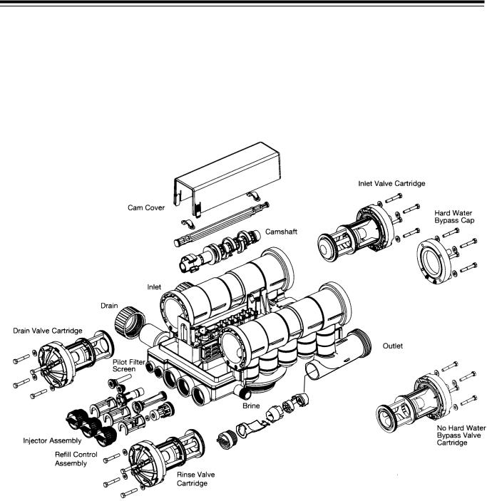
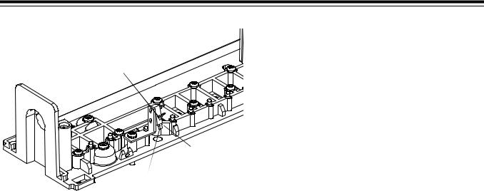
2.0 Introduction to the Magnum Cv and Magnum IT Series
The Magnum CvTM and Magnum ITTM Series valves offer a high degree of installation simplicity and flexibility.
Figure 2.1 provides an overview of the major components and connections of the 2-inch (5.08-cm) Magnum IT valve.
The Magnum valve is available in either a 1-1/2-inch (3.81-cm) (Magnum CvTM) or a 2-inch (5.08-cm) (Magnum IT™) configuration. Throughout
this manual, the 2-inch (5.08-cm) Magnum Cv is shown in illustrations where the model type is irrelevant to what is being demonstrated.
Magnum ITTM Series Valve
Internal Turbine
Assembly
Figure 2.1
2
2.1 Assembling the Control to the Magnum Valve
The control and the Magnum valve work together as an integral system to ensure synchronization. Follow the steps outlined below to install the control on the Magnum valve.
Remove Cam Cover
Remove the cam cover by pressing in on the cover release tabs (Figure 2.2). Note the cover locking tab and the slot in the top plate. When you reassemble the cover, the locking tab is placed in the slot first and the cover lowered into position.
Slide Camshaft
Slide the camshaft toward the back of the valve by pressing on the release tab and pulling on the back end of the camshaft (Figure 2.4). The front end of the camshaft will be flush with the mounting plate.
Release Tabs
Locking Tab and Slot
Cover Release Tabs
Figure 2.2
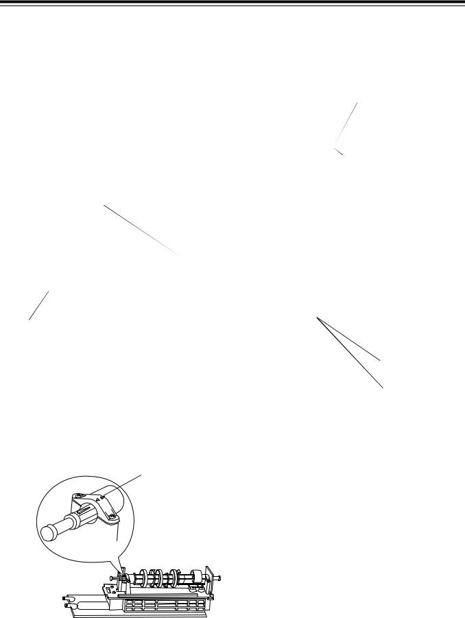
Align Camshaft
The camshaft is keyed and should only be engaged or disengaged when in the position illustrated (Figure 2.3). If the camshaft is not in the proper position, rotate the cam assembly counterclockwise until the camshaft arrow aligns with pillow block arrow.
Camshaft Arrow |
Pillow Block Arrow |
|
Figure 2.3
Figure 2.4
Mount Control
Mount the control onto the valve by sliding the mounting tabs over the mounting plate. Note that all models of Magnum controls mount to the valve in the same manner (Figure 2.5).
Mounting Tabs
Mounting Plate 
Figure 2.5
Engage Assembly
Engage the control by pressing on the release tab and pushing the camshaft into the control (Figure 2.6). Do not force the camshaft. If the camshaft does not slide freely into the control, check the alignment of the camshaft to ensure it is in the proper position
(Figure 2.3). The control indicator must be in the
REGENERATION COMPLETE position for the 942, 942Man, 952, and 962 when engaging the camshaft into the control. The control indicator must be in the BACKWASH COMPLETE position for the 942F, 942FMan 952F, and 962F when engaging the camshaft
3
into the control. The control indicator must be in the midpoint of the SERVICE position for the 962M and 962S when engaging the camshaft into the control.
Release Tab and
Camshaft
Figure 2.6
Important:
When 942, 942Man, 952, or 962 controls are installed, control dials must be in the REGENERATION COMPLETE position.
When 942F, 942FMan, or 952F controls are installed, control dials must be in the BACKWASH COMPLETE position.
When 962M or 962S controls are installed, control dials must be in the SERVICE position.
To disassemble the control from the valve, reverse the assembling procedure.
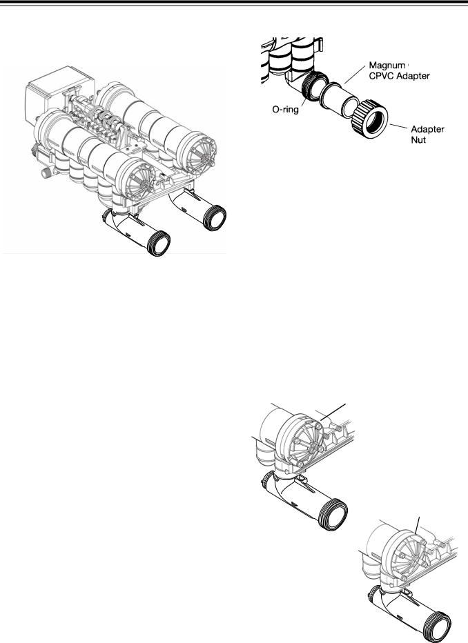
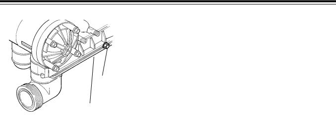
Inlet, Outlet and Drain Connections
The inlet, outlet, and drain connections are designed to accept an GE Osmonics supplied CPVC or brass adapter (Figure 2.7). The adapters provide a convenient union for the three connection ports on the valve. In addition, they incorporate a positive O-ring face seal for ease of installation and leak free operation. DO NOT OVERTIGHTEN THE ADAPTERS. As a general guideline, hand tightening the nut onto the valve will be adequate. If additional tightening is required, never exceed a quarter turn beyond the hand tight position.
The outlet of the 2-inch Magnum IT has an integrated turbine. The turbine measures the flow of water through the outlet. This information is used by the control to determine the best time to recycle.
Figure 2.7
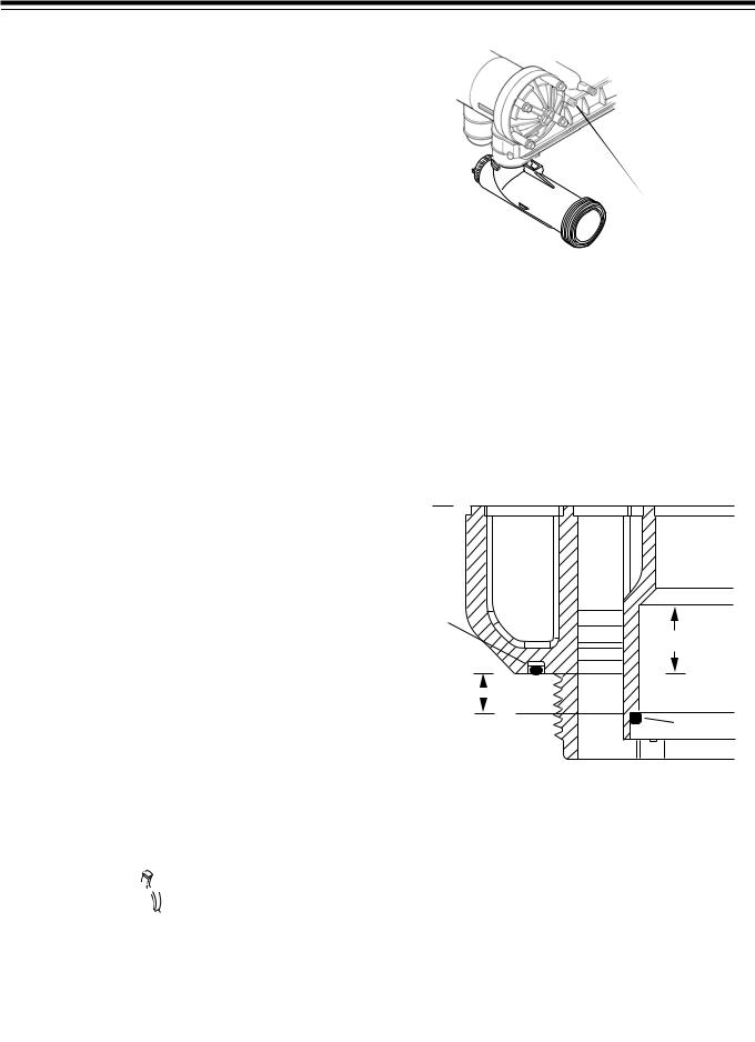
No Hardwater Bypass Feature
The Magnum control valve may be configured for “Hard Water Bypass” or “No Hard Water Bypass”. With Hard Water Bypass, unsoftened or unfiltered water is allowed to bypass the Magnum control valve during regeneration or backwash. With No Hard Water Bypass, a valve cartridge ensures that no unsoftened or unfiltered water bypasses the valve during regeneration or backwash.
It is easy to observe which option is installed in the valve. Note that the Hard Water Bypass End Cap has much longer standoffs than the No Hard Water Bypass cartridge. The No Hard Water Bypass assembly will look identical to the other three valve cartridges on the valve and will have a label identifying the cartridge assembly (Figure 2.8).
No Hard Water Bypass
No Unfiltered Water Bypass
Normal Standoffs
Extended Standoffs
With Hard Water Bypass
End Cap
Figure 2.8
4
Hydraulic Output Signal
An optional hydraulic output signal is available on the valve. An optional cam lobe on pilot valve #6 is used on the camshaft assembly to initiate the hydraulic output signal during regeneration or backwash (Figure 2.9).
The hydraulic line pressure signal will be available through the 1/4-inch connection on the back of the valve marked “AUX”. (Remove the tube cap installed for shipping.)
Optional cam lobes available are:
P/N 1000554 Provides a hydraulic signal from the beginning of BACKWASH through the start of REFILL.
P/N 1000553 Provides a hydraulic signal from the beginning of BACKWASH through the end of REFILL.
P/N 1001622 Used on Twin Alternating Systems Only. Provides a hydraulic signal from the beginning of BACKWASH through and during STANDBY.
P/N 1041064 Breakaway cam. Can be programmed to send a hydraulic signal at any time during the REGENERATION or BACKWASH cycle. Note: The camshaft must be turning for the signal to change states, i.e. switch from OFF to ON, or from ON to OFF.
For hydraulic output signal install one of following cam lobes:
1000553
1000554
1001622
1041064
Optional Cam
Lobe Position #6
“Hydraulic Output
Signal”
Figure 2.9
Auxiliary  Hydraulic
Output Port “AUX”
Pilot Drain Port
Figure 2.10
Magnum Tank Adapter
The tank adapter on the control valve is designed to be compatible with a 4 inch-8UN (8 threads per inch) tank opening. In addition, the adapter is designed to accept a full 1-1/2-inch (3.81-cm) riser pipe with outside diameter of 1.90 to 1.91 inches (48.26 to 48.51 mm) (Figure 2.11). The riser pipe is sealed by an O-ring on the inside of the tank adapter, Figure 2.11. It is recommended that the riser pipe extend beyond the top of the tank by 1/4 inch ± 3/8 inch (6 mm ± 9 mm).
TankO-ringO-ring
0.8125" (20.64 mm)
Top of Tank
.375" (9.52 mm)
RiserO-ringO-ring
Figure 2.11
Optional Switch Assembly
On single, twin parallel, and triple parallel tank configurations, a single optional feedback switch kit is available to provide an electrical signal during the entire regeneration or backwash cycle (Figure 2.12). The switch may be wired in the “Normally Open” or “Normally Closed” position and is rated for 0.1 amp at 125 volts AC. An optional 5.0 amp switch at 1/10 HP 125/250 volts AC is available upon request.
5
Common
Normally Open
Normally Closed
Figure 2.12
On ALL Magnum tank configurations, optional multiswitch kits are available to provide additional electrical or switch closure signals during the regeneration or backwash cycles. Coupled with the optional breakaway cams, signals can be sent to external system equipment at virtually any time while the control/camshaft motor is running. Consult the instruction sheet covering the multi-switch option for additional application and programming information. The instruction sheet is sent with the switch kit.
6
2.2 Magnum General Specifications
Operating and Environmental |
|
Operating Pressure ............................................................................................... |
25 to 125 psig (172 to 862 kPa) |
|
100 psig (688kPa) maximum in Canada |
Operating Water Temperature Range................................................................................. |
34 to 100oF (1 to 36oC) |
Ambient Temperature Range.............................................................................................. |
34 to 120oF (1 to 50oC) |
Cap Bolt Torque ................................................................................................... |
35-40 inch lbs. (3.95 to 4.51 Nm) |
Connections |
|
Inlet and Outlet................................................................................................................... |
1-1/2 inch-Magnum Cv |
|
2-inch-Magnum IT |
Tank ....................................................................................................................................................... |
4-inch-8UN |
Brine .................................................................................................................................................... |
3/4-inch NPT |
Pilot Drain and Auxiliary Hydraulic Out .................................................................................... |
1/4-inch tube fitting |
Riser Pipe Fitting ..................................................................................................................... |
1-1/2-inch (3.81-cm) |
Drain ........................................................................................................................................ |
1-1/2-inch (3.81-cm) |
Physical |
|
Dimensions..................................................................................................... |
Refer to drawings on pages 8 and 9 |
Approximate Weight (Valve and Control).................................................................................... |
23.3 lbs. (10.6 kg.) |
Electrical* |
|
Voltage - 962 Series Control .......................................................................... |
12 VAC wall mount transformer only |
Voltage - 942 Series Control .................................................................. |
120 VAC, 12 VAC wall mount transformer |
Voltage - 952 Series Control ........................................................................................................ |
24 VAC, 120 VAC |
Power Draw........................................................................................................................................ |
4.5 volt-amps |
*See section on Electronic Controls for alternative electrical configurations.
7
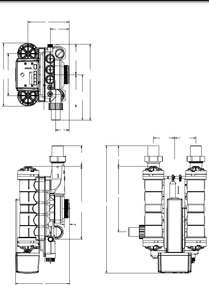
3.993 (10.14 cm)
6.493 (16.5 cm)
7.500 (19.05 cm)
22.796 (57.90 cm)
8
13.481 (34.24 cm)
9.000 (22.86 cm)
11.471 (29.13 cm)
8.680 (22.04 cm)
4.018 (10.20 cm)
2.817 (7.15 cm)
 7.000 (17.78 cm)
14.000 (35.56 cm)
19.500 (49.53 cm)
1.113 (2.82 cm)
15.539 (39.47 cm)
Inlet, inch-1/2 1 |
Cv Magnum 3.2 |
Drain and Outlet |
Specifications Dimensional |
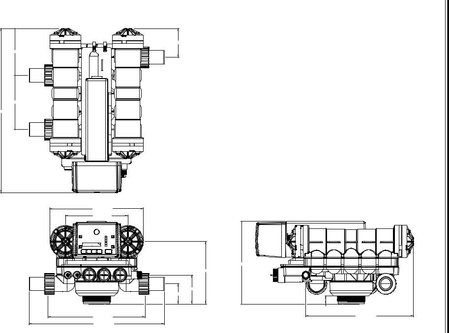
Magnum IT Dimensional Specifications 2-Inch Inlet and Outlet, 1 1/2-Inch Drain
13.481 |
9.000 |
8.710 3.998 6.500 16.250
7.000 |
9.750 |
||
|
|
|
|
|
|
|
|
|
|
|
|
|
|
|
|
2.817
4.429
15.539
1.113
11.376
4.500 |
4.500 |
4.429
13.993 |
27.224 |
9

3.0 General Installation Information
Please review the following items thoroughly to ensure an efficient and safe installation of the water treatment system. Page 12 shows typical installation line drawings for the Magnum valves.
Operating Conditions - A minimum dynamic operating water pressure of 25 psig (172 kPa) is required for the Magnum control valve to operate properly. Water pressure is not to exceed 125 psig (862 kPa). In Canada, water pressure is not to exceed 100 psig (688 kPa). Water temperature is not to exceed 100oF (36oC). Do not subject the valve to freezing conditions.
Space Requirements - Allow adequate space for the water treatment system and associated piping. The General Specifications section (pages 7-9) provides the overall dimensions of the control valve as well as the dimensional reference information for each of the connection ports. A minimum of 4 1/2 inches (11.5 cm) front and rear clearance is required for cartridge assembly and removal.
Plumbing - Always follow good plumbing practices and conform to local codes. Check existing pipes for lime and/or iron buildup. Replace piping if heavy buildup exists and initiate the proper treatment to prevent additional occurrences. Locate the equipment close to a drain that is capable of handling the maximum drain flow rate during backwash.
Flexible Connectors - Some tanks expand and contract over the acceptable range of operating water pressures of the Magnum control valve. The use of flexible connectors is recommended on polywound or fiberglass tank installations of 24-inch (60.96-cm) diameter and larger. Follow the tank manufacturer’s instructions for more information.
Inlet and Outlet Piping - Inlet and outlet plumbing should be adequately supported to avoid excessive loads on the valve. Install a manual bypass system to provide for occasions when the water conditioner must be bypassed for servicing.
Drain LIne Piping - To prevent mineral loss during backwash, and to ensure proper operation of the Magnum Cv Series control valve, A DRAIN LINE FLOW CONTROL must be plumbed into the drain line prior to placing the valve in the service mode. Flow controls from 5 to 40 gpm (18.92 to 151.4 Lpm) are available from GE Osmonics and can be easily installed in the drain line (Figure 3.1). Flow controls greater than 40 gpm (151.4 Lpm) must be plumbed externally. Selection of the proper drain line flow control will depend on the tank size and media used for the installation. See Table 10.3.
The following general drain line piping guidelines should be observed:
•1 inch (2.54 cm) or larger piping
•Should not exceed 20 feet (6.1 m)
•Should not be elevated higher than the control valve
•No shut-off valves should be installed in drain line
•Minimal number of elbows and fittings should be installed in drain line
•Piping must be self-supporting
•Install air gap to provide a siphon break
•Flow control should be installed as close to the Magnum Cv Series control valve as possible if an external flow control is used.
 Drain Line Flow Control Disk
Figure 3.1
Brining System - The Magnum control valve utilizes timed water refill to add water to the salt tank. A refill tube with check ball is required in the brine tank that will not restrict the refill or brine draw flow rate capabilities of the valve. Although not required, a separate brine valve (safety float) system is recommended for use with Magnum installations. Select a “High-Flow” brine valve that will not restrict the refill or brine draw flow rate capabilities of the valve. The “Performance Data and Charts” section (Section 10.0) of this manual contains flow rate information for various size injectors and refill controllers.
Pilot Drain - During regeneration, a small amount of water (200 ml or 1 cup) is discharged from the 1/4-inch (6.3-mm) tube fitting on the back of the valve marked DRAIN (Figure 3.2). To prevent this water from being discharged to the floor, plumb this connection to a nonpressurized drain or to the brine tank. Do not plug or apply back pressure to the pilot drain at any time.
Crimping the pilot drain line or installing the line to go up, which causes backpressure, will prevent the diaphragm cartridges from shifting properly through the cycles of regeneration or backwash.
10
Auxiliary Hydraulic
Output Port - Plugged
Pilot Drain Port
Figure 3.2
Electrical
1.Electrical requirements for the installation will depend on the configuration of the control.
2.The standard North American Series 962 electronic control is supplied with a 12 volt wall mount transformer. Optional wall mount transformers are available in the following configurations: Japanese plug @ 100 volts/50 or 60 Hz, Australian/Argentine plug @ 240 volts/50 Hz, British plug @ 240 volts/50 Hz, European/Italian plug @ 230 volts/50 Hz. Optional transformers must be ordered separately for all international 12 VAC configurations.
3.The standard North American Series 952 impulse controls use 120 VAC or 24 VAC/50 or 60 Hz power.
Lubricants
It is very important that 100% silicone lubricant is the only lubricant used for installing the Magnum control valve. Any other lubricant may cause material degradation and potential failure of the valve components.
NOTE: Some silicone based lubricants contain petroleum-based ingredients. If there is a question about the lubrication that you are using contact the manufacturer of that lubricant.
11
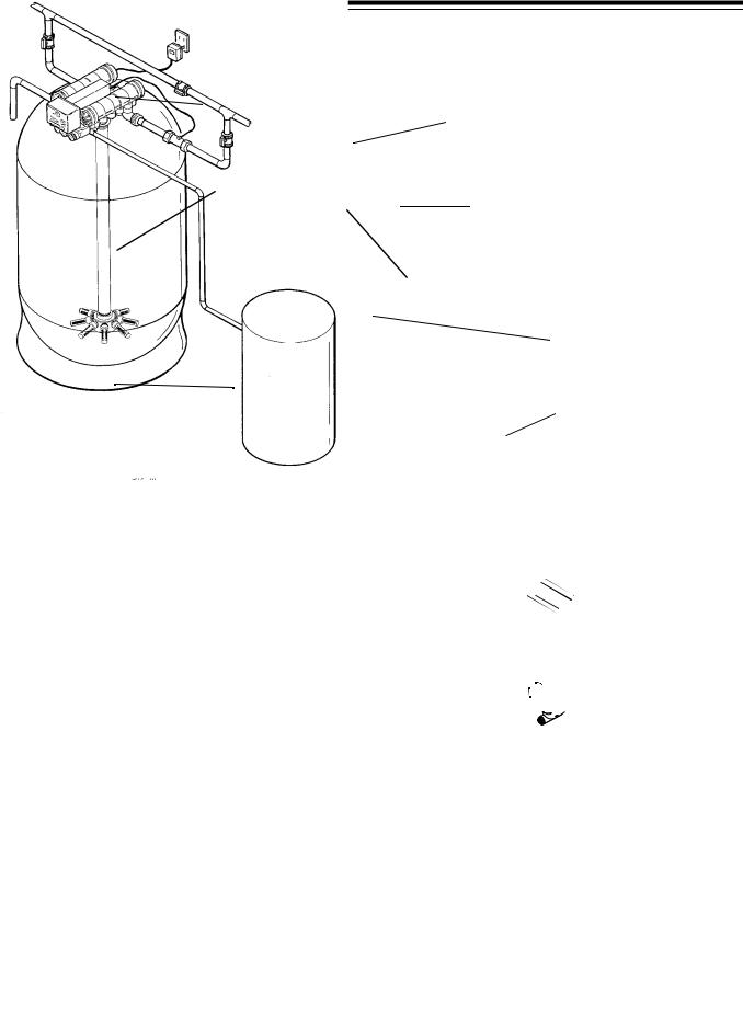
3.1 Typical Installation Drawings
Inlet Valve
Drain Line Flow Control (Required)
Drain
962 Control 
1.5” Riser Tube 
Hub & Lateral
Magnum Cv
Magnum IT
 Manual Bypass Valve
Outlet Valve
Note: Support Inlet and Outlet Piping
Turbine (standard Adequately. with 962 Control)
 Brine Line
 Brine Tank
Figure 3.3 Magnum Cv and Magnum IT, Single Tank Softener Units with 962 Electronic Control
12
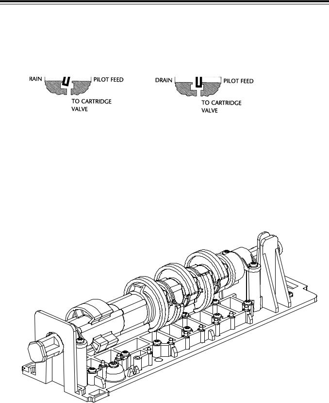
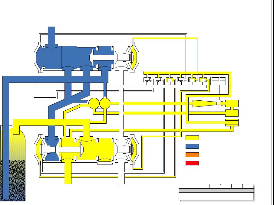
4.0 Flow Diagrams
The Magnum control valve utilizes a series of pilot valves to properly position the diaphragm valve cartridges (Figure 4.1). The pilot valves are activated by the camshaft (Figure 4.2). The flow diagrams that follow represent the Service Cycle for a 5-cycle softener, 3-cycle filter, and 5-cycle twin alternating softener
configuration. Both the Hardwater Bypass and No Hardwater Bypass service flow diagrams are presented.
Figure 4.1 Pilot Valve Principle of Operation
Figure 4.2 Cam Assembly
13
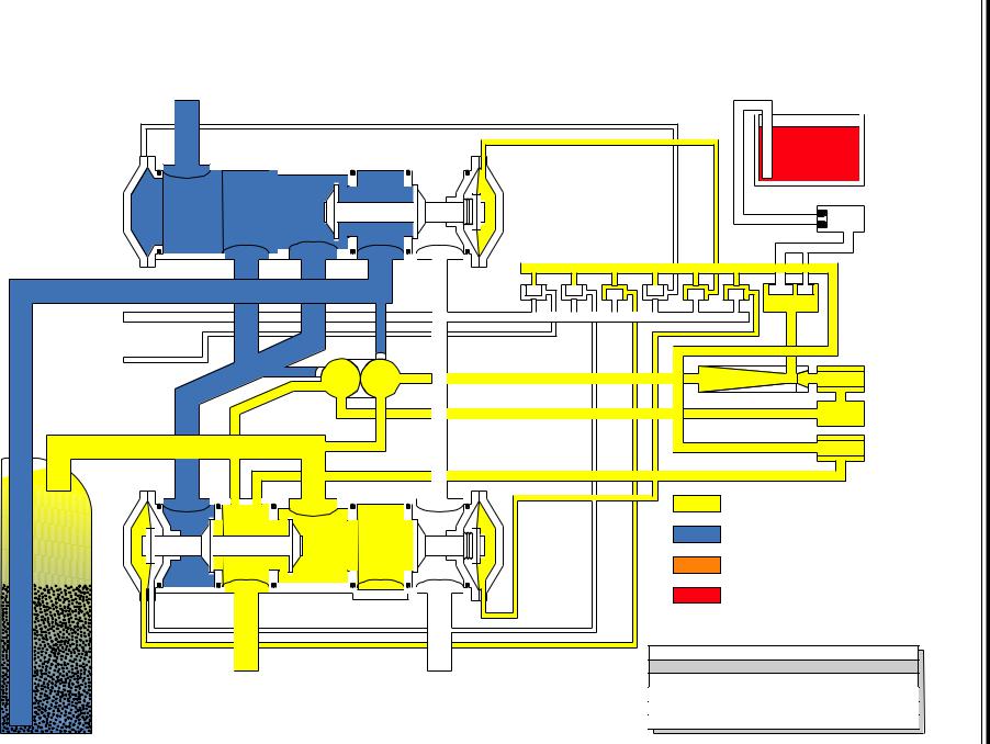
14
Magnum |
5 Cycle - Co-current - Hard Water Bypass - Softener |
Service Cycle
Outlet
|
|
|
|
|
|
|
|
|
Brine |
|
|
|
|
|
|
|
|
|
Tank |
Hard Water |
|
|
|
|
|
|
|
|
Refill |
Bypass |
|
|
|
|
|
|
|
|
|
|
|
|
|
|
|
|
|
|
Control |
3 |
2 |
|
|
|
|
|
|
|
|
Tank Bottom |
|
|
|
|
|
|
|
|
|
|
6 |
5 |
4 |
3 |
2 |
1 |
B2 |
B1 |
Pilot |
|
|
|
|
|
|
|
|
|
Valves |
Pilot Drain |
|
|
|
|
|
|
|
|
|
Aux. Pilot |
|
|
|
|
|
|
|
|
Injector |
Output |
|
|
|
|
|
|
|
|
|
|
|
|
|
|
|
|
|
Screen |
|
|
|
|
|
|
|
|
|
|
|
|
|
|
|
|
|
Injector |
|
Pressure |
|
|
|
|
|
|
|
|
|
|
|
Tank Top |
|
|
|
|
|
|
|
|
Regulator |
|
|
|
|
|
|
|
|
|
|
|
|
|
|
|
|
|
|
|
Pilot |
|
|
|
|
|
|
|
|
|
Screen |
4 |
1 |
|
|
|
|
Untreated |
|
|
|
|
|
|
|
|
|
Water |
|
|
|
Treated
Water
|
|
Backwash |
|
|
|
|
|
|
|
|
|
Water |
|
|
|
|
|
|
|
|
|
Regenerant |
|
|
|
|
|
|
|
|
|
6 |
5 |
4 |
3 |
2 |
1 |
B2 |
B1 |
|
|
Service CLSD |
CLSD OPEN CLSD OPEN OPEN CLSD CLSD |
||||||
Inlet |
Drain |
Backwash CLSD |
OPEN CLSD OPEN OPEN CLSD CLSD CLSD |
||||||
|
|
Brine/Slow Rinse CLSD |
OPEN CLSD OPEN CLSD OPEN OPEN OPEN |
||||||
|
|
Fast Rinse CLSD |
OPEN OPEN OPEN CLSD OPEN CLSD CLSD |
||||||
Resin Tank |
|
Refill/Service CLSD |
CLSD |
OPEN |
CLSD |
OPEN |
OPEN |
OPEN |
OPEN |
15
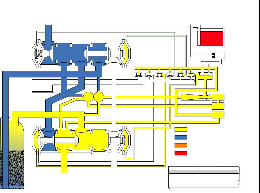
Magnum |
5 Cycle - Co-current - No Hard Water Bypass - Softener |
|
Service Cycle |
Outlet
No Hard
Water Bypass
3
Tank Bottom
Pilot Drain
Aux. Pilot
Output
Tank Top
4
2
6 |
5 |
4 |
3 |
2 |
1 |
B2 |
B1 |
|
|
|
|
|
Injector
1 |
Untreated |
|
Water |
|
Treated |
|
Water |
|
Backwash |
|
Water |
|
Regenerant |
Brine
Tank
Refill
Control
Pilot
Valves
Injector
Screen
Pressure
Regulator
Pilot
Screen
Inlet |
Drain |


 Resin Tank
6 |
5 |
4 |
3 |
2 |
1 |
B2 |
B1 |
Service CLSD CLSD OPEN CLSD OPEN |
OPEN |
CLSD |
CLSD |
||||
Backwash CLSD OPEN CLSD OPEN OPEN CLSD CLSD CLSD |
|||||||
Brine/Slow Rinse CLSD OPEN CLSD OPEN CLSD OPEN OPEN OPEN |
|||||||
Fast Rinse CLSD OPEN OPEN OPEN CLSD OPEN CLSD CLSD |
|||||||
Refill/Service CLSD |
CLSD |
OPEN |
CLSD |
OPEN |
OPEN |
OPEN |
OPEN |
16
Magnum |
3 Cycle - Unfiltered Water Bypass - Filter |
Service Cycle
Outlet
Unfiltered |
|
|
|
|
|
|
|
|
|
|
|
|
Water Bypass |
|
|
|
|
|
|
|
|
|
|
|
|
3 |
2 |
|
|
|
|
|
|
|
|
|
|
|
Tank Bottom |
|
|
|
|
|
|
|
|
|
|
|
|
|
6 |
5 |
4 |
3 |
2 |
1 |
B2 |
B1 |
|
|
Pilot |
|
|
|
|
|
|
|
|
|
|
|
|
Valves |
|
Pilot Drain |
|
|
|
|
|
|
|
|
|
|
|
|
Aux. Pilot |
|
|
|
|
|
|
|
|
|
|
|
|
Output |
|
|
|
|
|
|
|
|
|
|
|
|
|
|
|
|
|
|
Plugged Injector |
|
|
Pressure |
|||
|
|
|
|
|
|
|
|
|
|
|
||
Tank Top |
|
|
|
|
|
|
|
|
|
|
Regulator |
|
|
|
|
|
|
|
|
|
|
|
|
|
|
|
|
|
|
|
|
|
|
|
|
|
Pilot |
|
|
|
|
|
|
|
|
|
|
|
|
Screen |
|
4 |
1 |
|
|
|
|
Untreated |
|
|
|
|
|
|
|
|
|
|
|
|
Water |
|
|
|
|
|
|
|
|
|
|
|
|
Treated |
|
|
|
|
|
|
|
|
|
|
|
|
Water |
|
|
|
|
|
|
|
|
|
|
|
|
Backwash |
|
|
|
|
|
|
|
|
|
|
|
|
Water |
|
|
|
|
|
|
|
|
|
|
|
|
Regenerant |
|
|
|
|
|
|
Inlet |
Drain |
|
|
|
|
6 |
5 |
4 |
3 |
2 |
1 |
B2 B1 |
|
|
|
|
|
|
Service CLSD CLSD OPEN CLSD OPEN OPEN CLSD CLSD |
||||||
|
|
|
|
|
|
Backwash CLSD OPEN CLSD OPEN OPEN CLSD CLSD CLSD |
||||||
Media Tank |
|
|
|
|
|
Fast Rinse CLSD OPEN |
OPEN |
OPEN |
CLSD |
OPEN |
CLSD CLSD |
|
17
Magnum |
3 Cycle - No Unfiltered Water Bypass - Filter |
|
Service Cycle |
Outlet
No Unfiltered
Water Bypass
3
Tank Bottom
Pilot Drain
Aux. Pilot
Output
Tank Top
4
2
6 |
5 |
4 |
3 |
2 |
1 |
B2 |
B1 |
Pilot |
|
|
|
|
|
|
|
|
Valves |
Plugged Injector
Pressure
Regulator
Pilot
Screen
1 |
Untreated |
|
Water |
|
Treated |
|
Water |
|
Backwash |
|
Water |
Regenerant
Inlet |
Drain |
6 |
5 |
4 |
3 |
2 |
1 |
B2 B1 |
|
|
Service CLSD CLSD OPEN CLSD OPEN OPEN CLSD CLSD |
||||||
|
|
Backwash CLSD OPEN CLSD OPEN OPEN CLSD CLSD CLSD |
||||||
Media Tank |
|
Fast Rinse CLSD |
OPEN |
OPEN |
OPEN |
CLSD |
OPEN |
CLSD CLSD |

18
Magnum |
5 Cycle - Co-current - Twin Alternating Softener |
Service Cycle
Outlet
|
|
|
|
|
|
|
|
|
|
|
|
Brine |
||
|
|
|
|
|
|
|
|
|
|
|
|
Tank |
|
|
No Hard |
|
|
|
|
|
|
|
|
|
|
|
Refill |
|
|
Water Bypass |
|
|
|
|
|
|
|
|
|
|
|
|
||
|
|
|
|
|
|
|
|
|
|
|
|
Control |
||
3 |
2 |
|
|
|
|
|
|
|
|
|
|
|
|
|
Tank Bottom |
|
|
|
|
|
|
|
|
|
|
|
|
|
|
|
6 |
5 |
4 |
3 |
2 |
1 |
B2 |
B1 |
|
|
Pilot |
|
||
|
|
|
|
|
|
|
|
|
|
|
|
Valves |
||
Pilot Drain |
|
|
|
|
|
|
|
|
|
|
|
|
|
|
Aux. Pilot |
|
|
|
|
|
|
|
|
|
|
|
Injector |
||
Output |
|
|
|
|
|
|
|
|
|
|
|
|||
|
|
|
|
|
|
|
|
|
|
|
Screen |
|||
|
|
|
|
|
|
|
|
|
|
|
|
|||
|
|
|
|
|
|
Injector |
|
|
|
|
Pressure |
|||
|
|
|
|
|
|
|
|
|
|
|
|
|||
Tank Top |
|
|
|
|
|
|
|
|
|
|
|
Regulator |
||
|
|
|
|
|
|
|
|
|
|
|
|
|
|
|
|
|
|
|
|
|
|
|
|
|
|
|
Pilot |
|
|
|
|
|
|
|
|
|
|
|
|
|
|
Screen |
||
4 |
1 |
|
|
|
|
Untreated |
|
|
|
|
|
|
|
|
|
|
|
|
|
|
Water |
|
|
|
|
|
|
|
|
|
|
|
|
|
|
Treated |
|
|
|
|
|
|
|
|
|
|
|
|
|
|
Water |
|
|
|
|
|
|
|
|
|
|
|
|
|
|
Backwash |
|
|
|
|
|
|
|
|
|
|
|
|
|
|
Water |
|
|
|
|
|
|
|
|
|
|
|
|
|
|
Regenerant |
|
|
|
|
|
|
|
|
|
|
|
|
|
|
6 |
|
5 |
4 |
3 |
2 |
1 |
B2 |
B1 |
|
|
|
|
|
|
Service CLSD CLSD OPEN CLSD OPEN OPEN CLSD CLSD |
||||||||
|
|
|
|
|
|
First Standby CLSD CLSD OPEN OPEN OPEN OPEN CLSD CLSD |
||||||||
|
|
|
|
|
|
Backwash CLSD OPEN CLSD OPEN OPEN CLSD CLSD CLSD |
||||||||
Inlet |
Drain |
|
|
|
Brine/Slow Rinse CLSD |
OPEN |
CLSD |
OPEN CLSD OPEN OPEN OPEN |
||||||
|
|
|
|
|
|
Fast Rinse CLSD OPEN OPEN OPEN CLSD OPEN CLSD CLSD |
||||||||
|
|
|
|
|
|
Refill CLSD CLSD OPEN OPEN OPEN OPEN OPEN OPEN |
||||||||
Resin Tank |
|
|
|
|
Second Standby CLSD |
CLSD |
OPEN |
OPEN |
OPEN |
OPEN |
CLSD |
CLSD |
||
5.0Control Settings
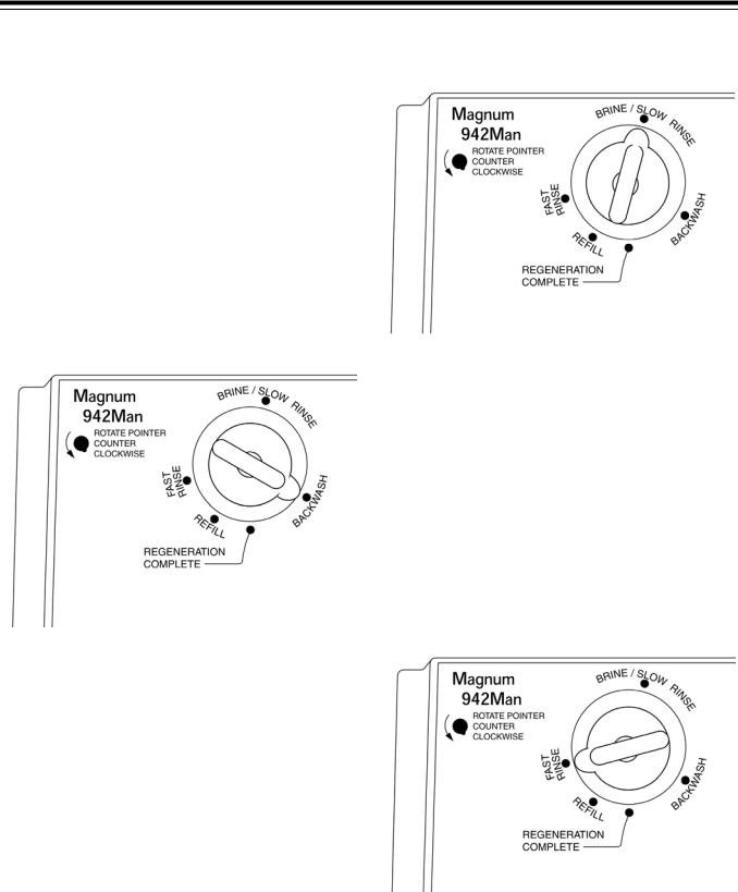
5.1Manual
Series 942Man Controls
The 942Man represents the maximum in versatility and ease of operation for the manual control valve system. Upgrade to an automatic system is easily accomplished by switching the manual control to a clock or demand control.
DO NOT TURN THE INDICATOR KNOB CLOCKWISE AT ANY TIME.
Regeneration Instructions
1.Move indicator knob COUNTERCLOCKWISE from the Regeneration Complete position to the center of the Backwash (Figure 5.1) position. DO NOT turn the knob clockwise.
Figure 5.1
2.The indicator knob should remain in the Backwash position for the appropriate amount of time. Specific backwash times are determined by the inlet water quality (i.e.: the amount of iron, manganese, turbidity), the amount of time between regenerations, water pressure, and flow. The typical backwash time is 10-15 minutes*. The unit should be in backwash until water at the drain is clear.
3.When the backwash is complete, move the indicator knob COUNTERCLOCKWISE to the center of the Brine/Slow Rinse position
(Figure 5.2). See the “Suggested Brine Draw/Slow Rinse Table” to determine the correct draw/rinse time. Please note that the tables are given at three salting levels and four pressures. The indicator knob should remain in the Brine/Slow Rinse position for the time* indicated in the table.
*Note: The times given are only general guidelines. Adjustment of the times may be necessary for specific applications and conditions.
Figure 5.2
4.When the slow rinse is complete, move the indicator knob COUNTERCLOCKWISE to the center of the Fast Rinse position (Figure 5.3). The indicator knob should remain in the Fast Rinse position for the appropriate amount of time. specific fast rinse times are determined by water quality, clarity of drain water, water pressure, and flow. Fast rinse serves to eliminate excess salt and repack the resin bed for the service run. Typically fast rinse should continue for 5 - 15 minutes*.
Important: If excessive fast rinse time is required to return the service effluent to quality, there could be an underlying cause, such as low pressure, fouled resin bed, fouled injector, etc.
Figure 5.3
5.When the fast rinse is complete, move the indicator knob COUNTERCLOCKWISE to the Refill position (Figure 5.4). Determine the correct refill time* from Table 5.1 below. The indicator knob should remain in the Refill position for the time indicated in the table.
19
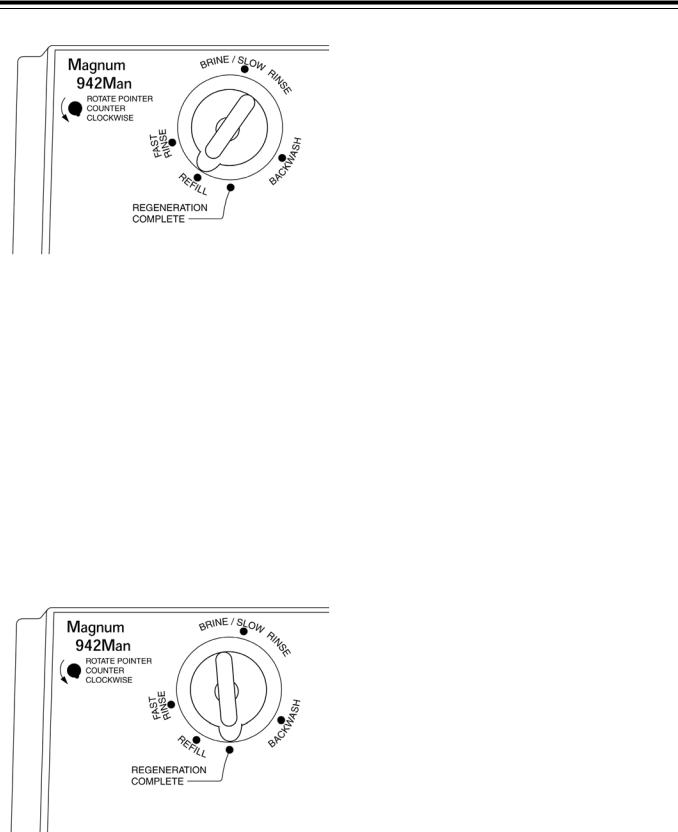
Figure 5.4
Table 5.1 Suggested Refill Times
Tank |
Resin |
|
Refill Flow Rate |
Minimum Salting |
Medium Salting |
Maximum |
|
Refill PN |
|
gpm (lpm) |
(6 lbs/ft3) |
(10 lbs/ft3) |
Salting (15 lb/ft3) |
||
Diameter |
cu.ft. |
|
@ 60 psig |
||||
|
|
(96.1 kg/m3) |
( 160.18 kg/m3) |
(240.27 kg/m3) |
|||
|
|
|
|
(414 kPa) |
|||
|
|
|
|
|
|
|
|
14 in (35.5 cm) |
3 |
1040679 |
0.7 |
(2.6 lpm) |
9 minutes |
15 minutes |
22 minutes |
|
|
|
|
|
|
|
|
16 in (40.6 cm) |
4 |
1040680 |
0.8 |
(3 lpm) |
10 minutes |
17 minutes |
25 minutes |
|
|
|
|
|
|
|
|
18 in (45.7 cm) |
5 |
1040681 |
1.0 |
(3.8 lpm) |
10 minutes |
17 minutes |
25 minutes |
|
|
|
|
|
|
|
|
21 in (53.5 cm) |
7 |
1040682 |
1.4 |
(5.31 lpm) |
10 minutes |
17 minutes |
25 minutes |
|
|
|
|
|
|
|
|
24 in (60.9 cm) |
10 |
1040683 |
2.0 |
(7.6 lpm) |
10 minutes |
17 minutes |
25 minutes |
|
|
|
|
|
|
|
|
30 in (76.2 cm) |
15 |
1040684 |
3.0 |
(11.4 lpm) |
10 minutes |
17 minutes |
25 minutes |
|
|
|
|
|
|
|
|
36 in (91.4 cm) |
20 |
1040685 |
5.0 |
(18.9 lpm) |
8 minutes |
14 minutes |
20 minutes |
6.When the refill is complete move the indicator knob COUNTERCLOCKWISE to the Regeneration Complete position (Figure 5.5). The unit will now provide softened water.
Figure 5.5
*Note: The times given are only general guidelines. Adjustment of the times may be necessary for specific applications and conditions.
Regenerating Iron Filters - Model 942Man
Refer to Regenerating Iron Filters Model 942 in Section 5.2 for information on this type of system application. All common control settings, control regenerant settings, and regenerant usage which apply to the 942Man control are the same as those used on the 942 control.
When using the 942Man control however, the time of each cycle cannot be predicted exactly. Note the following regeneration cycle parameters:
•Backwash the filter until the drain water flows clear, typically 5 - 15 minutes.
•Regenerant draw continues until the check ball closes to end draw.
•Slow Rinse should continue until there is NO pink color to the drain water flow. This is typically four times that of the regenerant draw time.
•Fast Rinse time continues until there is no pink color to the drain water flow, typically 5 - 15 minutes.
•Refill time is determined by the size of the refill flow control and the amount of regenerant required for a particular size system. Refer to Regenerant Use Table in Section 5.2.
20

Table 5.2 Suggested Brine Draw/Slow Rinse Times Based on 25 psi and 2.5 Bed Volumes of Slow Rinse
Tank Size in. (cm) |
14 (35.5) |
16 (40.6) |
18 (45.7) |
21 (53.3) |
24 (60.9) |
30 (76.2) |
36 (91.4) |
|
|
|
|
|
|
|
|
|
|
Resin Vol. cu. ft. (cu m) |
3 (0.085) |
4 (0.113) |
5 (0.142) |
7 (0.200) |
10 (0.283) |
15 (0.425) |
20 (0.566) |
|
|
|
|
|
|
|
|
|
|
|
|
|
|
|
|
|
|
|
Brine/ Rinse Time |
78 min |
72 min |
85 min |
73 min |
79 min |
89 min |
77 min |
|
|
|
|
|
|
|
|
|
|
Total Lb. Salt [Min.] (kg) |
18 (6.72) |
24 (8.96) |
30 (11.2) |
42 (15.68) |
60 (22.39) |
90 33.59) |
120 |
|
(44.79) |
||||||||
|
|
|
|
|
|
|
||
|
|
|
|
|
|
|
|
|
Capacity (kgr) |
60 |
80 |
100 |
140 |
200 |
300 |
400 |
|
|
|
|
|
|
|
|
|
|
|
|
|
|
|
|
|
|
|
Brine/Rinse Time |
87 min |
83 min |
98 min |
87 min |
89 min |
100 min |
86 min |
|
|
|
|
|
|
|
|
|
|
Total Lb. Salt [Mid] (kg) |
30 (11.2) |
40 (14.93) |
50 (18.66) |
70 (21.13) |
100 |
150 |
200 |
|
(37.32) |
(55.99) |
(74.65) |
||||||
|
|
|
|
|
||||
|
|
|
|
|
|
|
|
|
Capacity (kgr) |
75 |
100 |
125 |
175 |
250 |
375 |
500 |
|
|
|
|
|
|
|
|
|
|
|
|
|
|
|
|
|
|
|
Brine/Rinse Time |
99 min |
98 min |
113 min |
103 min |
102 min |
114 min |
98 min |
|
|
|
|
|
|
|
|
|
|
Total Lb. Salt [Max] |
45 (16.8) |
60 (22.39) |
75 (27.99) |
105 (39.19 |
150 |
225 |
300 |
|
(55.99) |
(83.98) |
(111.97) |
||||||
|
|
|
|
|
||||
|
|
|
|
|
|
|
|
|
Capacity (kgr) |
90 |
120 |
150 |
210 |
300 |
450 |
600 |
|
|
|
|
|
|
|
|
|
|
|
|
|
|
|
|
|
|
|
Injector Number |
1000441 |
1000442 |
1000443 |
1000444 |
1000445 |
1000446 |
1000447 |
|
|
|
|
|
|
|
|
|
Table 5.3 Suggested Brine Draw/Slow Rinse Times Based on 50 psi and 2.5 Bed Volumes of Slow Rinse
Tank Size in. (cm) |
14 (35.5) |
16 (40.6) |
18 (45.7) |
21 (53.3) |
24 (60.9) |
30 (76.2) |
36 (91.4) |
|
|
|
|
|
|
|
|
|
|
Resin Vol. cu. ft. (cu m) |
3 (0.085) |
4 (0.113) |
5 (0.142) |
7 (0.200) |
10 (0.283) |
15 (0.425) |
20 (0.566) |
|
|
|
|
|
|
|
|
|
|
|
|
|
|
|
|
|
|
|
Brine/ Rinse Time |
65 min |
58 min |
70 min |
65 min |
66 min |
76 min |
68 min |
|
|
|
|
|
|
|
|
|
|
Total Lb. Salt [Min.] (kg) |
18 (6.72) |
24 (8.96) |
30 (11.2) |
42 (15.68) |
60 (22.39) |
90 33.59) |
120 |
|
(44.79) |
||||||||
|
|
|
|
|
|
|
||
|
|
|
|
|
|
|
|
|
Capacity (kgr) |
60 |
80 |
100 |
140 |
200 |
300 |
400 |
|
|
|
|
|
|
|
|
|
|
|
|
|
|
|
|
|
|
|
Brine/Rinse Time |
74 min |
70 min |
83 min |
77 min |
77 min |
87 min |
77 min |
|
|
|
|
|
|
|
|
|
|
Total Lb. Salt [Mid] (kg) |
30 (11.2) |
40 (14.93) |
50 (18.66) |
70 (21.13) |
100 |
150 |
200 |
|
(37.32) |
(55.99) |
(74.65) |
||||||
|
|
|
|
|
||||
|
|
|
|
|
|
|
|
|
Capacity (kgr) |
75 |
100 |
125 |
175 |
250 |
375 |
500 |
|
|
|
|
|
|
|
|
|
|
|
|
|
|
|
|
|
|
|
Brine/Rinse Time |
99 min |
85 min |
98 min |
94 min |
90 min |
101 min |
89 min |
|
|
|
|
|
|
|
|
|
|
Total Lb. Salt [Max] |
45 (16.8) |
60 (22.39) |
75 (27.99) |
105 (39.19 |
150 |
225 |
300 |
|
(55.99) |
(83.98) |
(111.97) |
||||||
|
|
|
|
|
||||
|
|
|
|
|
|
|
|
|
Capacity (kgr) |
90 |
120 |
150 |
210 |
300 |
450 |
600 |
|
|
|
|
|
|
|
|
|
|
|
|
|
|
|
|
|
|
|
Injector Number |
1000441 |
1000442 |
1000443 |
1000444 |
1000445 |
1000446 |
1000447 |
|
|
|
|
|
|
|
|
|
21

Table 5.4 Suggested Brine Draw/Slow Rinse Times Based on 75 psi and 2.5 Bed Volumes of Slow Rinse
Tank Size in. (cm) |
14 (35.5) |
16 (40.6) |
18 (45.7) |
21 (53.3) |
24 (60.9) |
30 (76.2) |
36 (91.4) |
|
|
|
|
|
|
|
|
|
|
Resin Vol. cu. ft. (cu m) |
3 (0.085) |
4 (0.113) |
5 (0.142) |
7 (0.200) |
10 (0.283) |
15 (0.425) |
20 (0.566) |
|
|
|
|
|
|
|
|
|
|
|
|
|
|
|
|
|
|
|
Brine/ Rinse Time |
55 min |
52 min |
61 min |
57 min |
58 min |
66 min |
55 min |
|
|
|
|
|
|
|
|
|
|
Total Lb. Salt [Min.] (kg) |
18 (6.72) |
24 (8.96) |
30 (11.2) |
42 (15.68) |
60 (22.39) |
90 33.59) |
120 |
|
(44.79) |
||||||||
|
|
|
|
|
|
|
||
|
|
|
|
|
|
|
|
|
Capacity (kgr) |
60 |
80 |
100 |
140 |
200 |
300 |
400 |
|
|
|
|
|
|
|
|
|
|
|
|
|
|
|
|
|
|
|
Brine/Rinse Time |
64 min |
64 min |
73 min |
70 min |
69 min |
76 min |
64 min |
|
|
|
|
|
|
|
|
|
|
Total Lb. Salt [Mid] (kg) |
30 (11.2) |
40 (14.93) |
50 (18.66) |
70 (21.13) |
100 |
150 |
200 |
|
(37.32) |
(55.99) |
(74.65) |
||||||
|
|
|
|
|
||||
|
|
|
|
|
|
|
|
|
Capacity (kgr) |
75 |
100 |
125 |
175 |
250 |
375 |
500 |
|
|
|
|
|
|
|
|
|
|
|
|
|
|
|
|
|
|
|
Brine/Rinse Time |
75 min |
79 min |
88 min |
85 min |
82 min |
90 min |
75 min |
|
|
|
|
|
|
|
|
|
|
Total Lb. Salt [Max] |
45 (16.8) |
60 (22.39) |
75 (27.99) |
105 (39.19 |
150 |
225 |
300 |
|
(55.99) |
(83.98) |
(111.97) |
||||||
|
|
|
|
|
||||
|
|
|
|
|
|
|
|
|
Capacity (kgr) |
90 |
120 |
150 |
210 |
300 |
450 |
600 |
|
|
|
|
|
|
|
|
|
|
|
|
|
|
|
|
|
|
|
Injector Number |
1000441 |
1000442 |
1000443 |
1000444 |
1000445 |
1000446 |
1000447 |
|
|
|
|
|
|
|
|
|
Table 5.5 Suggested Brine Draw/Slow Rinse Times Based on 100 psi and 2.5 Bed Volumes of Slow Rinse
Tank Size in. (cm) |
14 (35.5) |
16 (40.6) |
18 (45.7) |
21 (53.3) |
24 (60.9) |
30 (76.2) |
36 (91.4) |
|
|
|
|
|
|
|
|
|
|
Resin Vol. cu. ft. (cu m) |
3 (0.085) |
4 (0.113) |
5 (0.142) |
7 (0.200) |
10 (0.283) |
15 (0.425) |
20 (0.566) |
|
|
|
|
|
|
|
|
|
|
|
|
|
|
|
|
|
|
|
Brine/ Rinse Time |
50 min |
48 min |
56 min |
53 min |
54 min |
59 min |
50 min |
|
|
|
|
|
|
|
|
|
|
Total Lb. Salt [Min.] (kg) |
18 (6.72) |
24 (8.96) |
30 (11.2) |
42 (15.68) |
60 (22.39) |
90 33.59) |
120 |
|
(44.79) |
||||||||
|
|
|
|
|
|
|
||
|
|
|
|
|
|
|
|
|
Capacity (kgr) |
60 |
80 |
100 |
140 |
200 |
300 |
400 |
|
|
|
|
|
|
|
|
|
|
|
|
|
|
|
|
|
|
|
Brine/Rinse Time |
59 min |
60 min |
68 min |
65 min |
64 min |
69 min |
59 min |
|
|
|
|
|
|
|
|
|
|
Total Lb. Salt [Mid] (kg) |
30 (11.2) |
40 (14.93) |
50 (18.66) |
70 (21.13) |
100 |
150 |
200 |
|
(37.32) |
(55.99) |
(74.65) |
||||||
|
|
|
|
|
||||
|
|
|
|
|
|
|
|
|
Capacity (kgr) |
75 |
100 |
125 |
175 |
250 |
375 |
500 |
|
|
|
|
|
|
|
|
|
|
|
|
|
|
|
|
|
|
|
Brine/Rinse Time |
70 min |
75 min |
83 min |
81 min |
77 min |
82 min |
70 min |
|
|
|
|
|
|
|
|
|
|
Total Lb. Salt [Max] |
45 (16.8) |
60 (22.39) |
75 (27.99) |
105 (39.19 |
150 |
225 |
300 |
|
(55.99) |
(83.98) |
(111.97) |
||||||
|
|
|
|
|
||||
|
|
|
|
|
|
|
|
|
Capacity (kgr) |
90 |
120 |
150 |
210 |
300 |
450 |
600 |
|
|
|
|
|
|
|
|
|
|
|
|
|
|
|
|
|
|
|
Injector Number |
1000441 |
1000442 |
1000443 |
1000444 |
1000445 |
1000446 |
1000447 |
|
|
|
|
|
|
|
|
|
Minimum salting: 6 lb. salt = 20 kgr/cu. ft.
Medium salting: 10 lb. salt = 25 kgr/cu. ft.
Maximum salting: 15 lb. salt = 30 kgr/cu. ft.
22
Loading...