


WATSON-MARLOW MANUALS
m-qdos30-universal+-gb-10
Watson-Marlow qdos30
Universal and Universal+ pump
Contents
1 |
Declaration of conformity................................................................ |
3 |
|
2 |
Declaration of incorporation............................................................. |
4 |
|
3 |
Warranty....................................................................................... |
5 |
|
4 |
When you unpack your pump........................................................... |
6 |
|
5 |
Information for returning pumps...................................................... |
7 |
|
6 |
Safety notes.................................................................................. |
8 |
|
7 |
Pump specifications...................................................................... |
10 |
|
|
7.1 |
Dimensions.......................................................................... |
12 |
|
7.2 |
Weights............................................................................... |
12 |
8 |
Good pump installation practice..................................................... |
13 |
|
|
8.1 |
General recommendations...................................................... |
13 |
|
8.2 Do’s and do not’s.................................................................. |
14 |
|
9 |
Connecting to a power supply........................................................ |
15 |
|
10 |
Start-up check list........................................................................ |
16 |
|
11 |
Automatic control wiring - standard pump....................................... |
17 |
|
|
11.1 Input pin assignments at the pump.......................................... |
17 |
|
|
11.2 Optional input lead................................................................ |
18 |
|
|
11.3 Output pin assignments at the pump....................................... |
19 |
|
|
11.4 Optional output lead.............................................................. |
20 |
|
12 |
Automatic control wiring - module.................................................. |
21 |
|
|
12.1 Module: cover removal and refitting......................................... |
21 |
|
|
12.2 Wiring up the terminal connectors........................................... |
22 |
|
|
12.3 24 volt relay module pcb connectors........................................ |
24 |
|
13 |
Switching on the pump for the first time...................................................... |
27 |
|
14 |
Switching the pump on in subsequent power cycles........................... |
29 |
|
15 |
Pump operation........................................................................... |
30 |
|
|
15.1 Keypad functions................................................................... |
30 |
|
|
15.2 MODE menu......................................................................... |
32 |
|
|
15.3 Manual................................................................................ |
33 |
|
|
15.4 Flow calibration..................................................................... |
35 |
|
|
15.5 Analog 4-20mA mode............................................................ |
37 |
|
|
15.6 Calibrate the pump for 4-20mA control............................................. |
41 |
|
16 |
Contact Mode.............................................................................. |
44 |
|
|
16.1 Contact Settings................................................................... |
44 |
|
|
16.2 Contact operating mode......................................................... |
46 |
|
17 |
Fluid recovery mode..................................................................... |
47 |
|
|
17.1 Remote fluid recovery............................................................ |
49 |
|
18 |
Main menu.................................................................................. |
50 |
|
|
18.1 Fluid level monitor................................................................. |
51 |
|
|
18.2 Security settings................................................................... |
54 |
|
|
18.3 General settings.................................................................... |
57 |
|
|
18.4 MODE menu......................................................................... |
61 |
|
|
18.5 Control settings.................................................................... |
61 |
|
|
18.6 Help ................................................................................... |
65 |
|
19 |
Troubleshooting........................................................................... |
66 |
|
|
19.1 Leak detection...................................................................... |
66 |
|
|
19.2 Error codes........................................................................... |
67 |
|
|
19.3 Technical support.................................................................. |
67 |
|
20 |
Drive maintenance....................................................................... |
68 |
|
Watson-Marlow qdos30 Universal and Universal+ Pump User Manual |
1 |
||
21 |
Pumphead replacement................................................................. |
69 |
|
21.1 Connecting interface tubing.................................................... |
72 |
22 |
Ordering information.................................................................... |
75 |
|
22.1 Pump part numbers............................................................... |
75 |
|
22.2 Spares and accessories.......................................................... |
76 |
23 |
Performance data......................................................................... |
77 |
|
23.1 Pumping conditions............................................................... |
77 |
|
23.2 Pressure capability................................................................ |
77 |
|
23.3 Dry running.......................................................................... |
77 |
|
23.4 Pumphead life....................................................................... |
77 |
|
23.5 Performance curves............................................................... |
77 |
24 |
Trademarks................................................................................. |
78 |
25 |
Publication history........................................................................ |
78 |
Watson-Marlow qdos30 Universal and Universal+ Pump User Manual |
2 |

1 Declaration of conformity
EC Declaration of Conformity
Watson-Marlow Ltd
Falmouth
Cornwall
TR11 4RU
England
Description |
qdos30 peristaltic pumps |
Products |
qdos30 manual, qdos30 remote, qdos30 universal, qdos30 universal+, |
|
qdos30 PROFIBUS, qdos30 universal 110volt logic, qdos30 universal+ 110volt |
|
logic, qdos30 universal 24volt logic, qdos30 universal+ 24volt logic. |
Conformity |
Watson-Marlow Ltd declares that when this pump unit is used as a stand-alone |
|
pump it complies with Machinery Directive 2006/42/EC. |
Standards |
Watson-Marlow Limited declares that the above stated products are in |
|
conformance with the following harmonised standards and directives: |
|
Low Voltage Directive 2006/95/EC. |
|
Electro-Magnetic Compatibility Directive 2004/108/EC. |
|
Safety of Machinery-Electrical equipment of machines; BS EN 60204-1 |
|
Safety requirements for electrical equipment for measurement, control and laboratory use; |
|
BS EN 61010-1 IEC 61010-1 UL 61010-1 |
|
Safety of machinery-Basic concepts, general principals of design BS EN ISO 12100-1 and |
|
BS EN ISO 12100-2 |
|
Degrees of protection provided by enclosures (IP code) BS EN 60529 |
|
Information Technology equipment safety BS EN 60950-1 |
|
Digital Data Communication BS EN 61138-2 |
|
Conducted emissions BS EN 55011 Class A |
|
Radiated emissions BS EN 55011 Class A |
|
Electrostatic discharge immunity BS EN 61000-4-2 |
|
Radiated RF immunity BS EN 61000-4-3 |
|
Fast transient/burst immunity BS EN 61000-4-4 |
|
Surge immunity testing BS EN 61000-4-5 |
|
Conducted RF immunity BS EN 61000-4-6 |
|
Voltage dips and interruptions BS EN 61000-4-11 |
|
Mains harmonics BS EN 61000-3-2 |
Manufacturer |
Watson-Marlow Limited, TR11 4RU, England |
Date |
17th August 2012 |
Signature |
|
|
David Cole, Managing Director, Watson-Marlow Limited |
This pump is ETL listed: ETL control number 3050250. Cert to CAN/CSA std C22.2 No 61010-1. Conforms to UL std 61010A-1.
See 7 Pump specifications on page 10.
Watson-Marlow qdos30 Universal and Universal+ Pump User Manual |
3 |

2 Declaration of incorporation
Declaration of Incorporation
Watson-Marlow Ltd
Falmouth
Cornwall
TR11 4RU
England
In accordance with the Machinery Directive 2006/42/EC that if this unit is to be installed into a machine or is to be assembled with other machines for installations, it shall not be put into service until the relevant machinery has been declared in conformity.
We hereby declare that:
Peristaltic Pump qdos
Series: qdos 30
that the following harmonized standards have been applied and fulfilled for health and safety requirements:
Safety of Machinery - EN ISO 12100
Safety of Machinery – Electrical Equipment of Machines EN 60204-1.
Quality Management System - ISO 9001.
and the technical documentation is compiled in accordance with Annex VII(B) of the Directive.
We undertake to transmit, in response to a reasoned request by the appropriate national authorities, relevant information on the partly completed machinery identified above. The method of transmission shall be by mail or email.
The pump head is incomplete and must not be put into service until the machinery into which it is to be incorporated has been declared in conformity with the provisions of the Directive.
Person authorized to compile the technical documents:
Andrew Green
…………………………………… of Watson-Marlow Ltd.
Place and date of declaration: Watson-Marlow Ltd, 17th August 2012
Responsible person:
Mr. David Cole
Managing Director for Watson-Marlow Ltd
The information in this user guide is believed to be correct at the time of publication. However, Watson-Marlow Limited accepts no liability for errors or omissions. WatsonMarlow has a policy of continuous product improvement, and reserves the right to alter specifications without notice. This manual is intended for use only with the pump it was issued with. Earlier or later models may differ. The most up-to-date manuals appear on the Watson-Marlow website: http://www.wmpg.com
Watson-Marlow qdos30 Universal and Universal+ Pump User Manual |
4 |
3 Warranty
Watson-Marlow Ltd (“Watson-Marlow”) warrants this product to be free from defects in materials and workmanship for three years from the date of shipment, under normal use and service.
Watson-Marlow’s sole responsibility and the customer’s exclusive remedy for any claim arising out of the purchase of any product from Watson-Marlow is, at WatsonMarlow’s option: repair, replacement or credit, where applicable.
Unless otherwise agreed in writing, the foregoing warranty is limited to the country in which the product is sold.
No employee, agent or representative of Watson-Marlow has the authority to bind Watson-Marlow to any warranty other than the foregoing unless in writing and signed by a director of Watson-Marlow. Watson-Marlow makes no warranty of the fitness of its products for a particular purpose.
In no event:
(i)shall the cost of the customer’s exclusive remedy exceed the purchase price of the product;
(ii)shall Watson-Marlow be liable for any special, indirect, incidental, consequential, or exemplary damages, however arising, even if Watson-Marlow has been advised of the possibility of such damages.
Watson-Marlow shall not be liable for any loss, damage, or expense directly or indirectly related to or arising out of the use of its products, including damage or injury caused to other products, machinery, buildings, or property. Watson-Marlow shall not be liable for consequential damages, including, without limitation, lost profits, loss of time, inconvenience, loss of product being pumped, and loss of production.
This warranty does not obligate Watson-Marlow to bear any costs of removal, installation, transportation, or other charges which may arise in connection with a warranty claim.
Watson-Marlow shall not be responsible for shipping damage of returned items.
Conditions
•Products must be returned by pre-arrangement to Watson-Marlow, or a WatsonMarlow approved service centre.
•All repairs or modifications must have been made by Watson-Marlow Ltd, or a
Watson-Marlow approved service centre or with the express permission in writing of Watson-Marlow, signed by a manager or director of Watson-Marlow.
•Any remote control or system connections must be made in accordance to Watson-Marlow recommendations.
•All PROFIBUS systems must be installed or certified by a PROFIBUS approved installation engineer.
Exceptions
•Consumable items including tubing and pumping elements are excluded.
•Pumphead rollers are excluded.
•Repairs or service necessitated by normal wear and tear or by lack of reasonable and proper maintenance are excluded.
•Products which, in the judgment of Watson-Marlow, have been abused, misused, or subjected to malicious or accidental damage or neglect are excluded.
•Failure caused by electrical surge is excluded.
•Failure caused by incorrect or sub-standard system wiring is excluded.
•Damage by chemical attack is excluded.
•Ancillaries such as leak detectors are excluded.
•Failure caused by UV light or direct sunlight.
•All ReNu pumpheads are excluded.
•Any attempt to disassemble a Watson-Marlow product will invalidate the product warranty.
Watson-Marlow reserves the right to amend these terms and conditions at any time.
Watson-Marlow qdos30 Universal and Universal+ Pump User Manual |
5 |

4 When you unpack your pump
Unpack all parts carefully, retaining the packaging until you are sure all components are present and in good order. Check against the components supplied list, below.
Packaging disposal
Dispose of packaging materials safely, and in accordance with regulations in your area. The outer carton is made of corrugated cardboard and can be recycled.
Inspection
Check that all components are present. Inspect components for damage in transit. If anything is missing or damaged, contact your distributor immediately.
Components supplied
•qdos30 pump drive unit
•ReNu pumphead
•User connection collars
•The designated power cable (attached to the pump drive unit)
•CD-ROM containing these operating instructions
•Quick start manual
•Product safety information booklet
Optional accessories
•Additional ReNu pumphead
•HMI protective cover
•Interface tubing
•Input and output (I/O) leads
Storage
This product has an extended shelf life. However, care should be taken after storage to ensure that all parts function correctly. Please observe the storage recommendations and use-by dates which apply to tubing you may wish to bring into service after storage.
Watson-Marlow qdos30 Universal and Universal+ Pump User Manual |
6 |
5 Information for returning pumps
In compliance with the UK Health and Safety at Work Act and the Control of Substances Hazardous to Health Regulations, you are required to declare the substances which have been in contact with product(s) you return to Watson-Marlow or its subsidiaries or distributors. Failure to do so will cause delays. Please ensure that you fax us this form and receive an RGA (Returned Goods Authorisation) before you despatch the product(s). A copy of this form must be attached to the outside of the packaging containing the product(s).
Please complete a separate decontamination certificate for each product. A copy of the appropriate decontamination certificate can be downloaded from the Watson-
Marlow website at: www.wmpg.com/decon
You are responsible for cleaning and decontaminating the product(s) before return.
Watson-Marlow qdos30 Universal and Universal+ Pump User Manual |
7 |
6 Safety notes
In the interests of safety, this pump and pumphead should only be used by competent, suitably trained personnel after they have read and understood this manual, and considered any hazard involved. If the pump is used in a manner not specified by
Watson-Marlow Ltd, the protection provided by the pump may be impaired.
Any person who is involved in the installation or maintenance of this equipment should be fully competent to carry out the work. In the UK this person should also be familiar with the Health and Safety at Work Act 1974.
This symbol, used on the pump and in this manual, means: Caution, refer to accompanying documents.
This symbol, used on the pump and in this manual, means: Do not allow fingers to contact moving parts.
This symbol, used on the pump and in this manual, means: Caution, hot surface.
Fundamental work with regard to lifting, transportation, installation, starting-up, maintenance and repair should be performed by qualified personnel only. The unit must be isolated from mains power while work is being carried out. The motor must be secured against accidental start-up.
There is a non-replaceable fuse on the switch-mode power supply board. In some countries, the mains power plug contains a replaceable fuse. There are no user-serviceable fuses or parts inside this pump.
This pump must be used only for its intended purpose.
The pump must be accessible at all times to facilitate operation and maintenance.
Access points must not be obstructed or blocked. Do not fit any devices to the drive unit other than those tested and approved by Watson-Marlow. Doing so could lead to injury to persons or damage to property for which no liability can be accepted.
If hazardous fluids are to be pumped, safety procedures specific to the particular fluid and application must be put in place to protect against injury to persons.
The exterior surfaces of the pump may get hot during operation. Do not take hold of the pump while it is running. Let the pump cool after use before handling. The drive unit must not be run without a pumphead fitted.
This product does not comply with the ATEX directive and must not be used in explosive atmospheres.
If pumping flammable liquids, a full risk assessment should be completed prior to use.
Watson-Marlow qdos30 Universal and Universal+ Pump User Manual |
8 |

The exterior surfaces of the pump may get hot during operation. Do not take hold of the pump while it is running. Allow the to pump cool after use before handling. The drive unit must not be run without a pumphead fitted. The pumphead should not be run dry for extended periods of time. The pump should not be
used to pump fluids where the temperature of the fluid can reach temperatures of more than 70C.
Ensure the chemicals to be pumped are compatible with the pumphead, lubricant, tubing, pipework and fittings to be used with the pump. Please refer to the chemical compatibility guide which can be found at: www.wmpg.com/chemical If you need to use the pump with any other chemical please contact Watson-
Marlow to confirm compatibility.
Watson-Marlow qdos30 Universal and Universal+ Pump User Manual |
9 |
7 Pump specifications
ReNu pumphead (left hand mounted)
 Mounting plate
Pumphead retaining clamps
Outlet
 HMI
HMI
(not Remote)
 Drive unit
Inlet
Power
A nameplate is fixed to the rear of the pump. It contains manufacturer and contact details, product reference number, serial number and model details.
0M0.223L.GLU Iss 1 Product reference
qdos Manual 30l/hr 7bar Model 190gpd 100psi marp glycol
Serial Number  Serial number
Manufacturer details
Watson-Marlow qdos30 Universal and Universal+ Pump User Manual |
10 |
Pump specifications
Flow Range (flow control) |
0.1-500 ml/min (5000:1) |
Supply voltage/frequency |
~100-240V 50/60Hz |
±10% of nominal voltage. |
An electrical mains supply is required |
Maximum voltage fluctuation |
along with cable connections to the best |
|
practice of noise immunity |
Installation category |
II |
(overvoltage category) |
|
Power consumption |
190VA |
Enclosure rating |
IP66 to BS EN 60529 |
|
NEMA 4X to NEMA 250* |
Operating temperature range |
4C to 45C, 41F to 113F |
Storage temperature range |
-20C to 70C, -4F to 158F |
Maximum altitude |
2,000m, 6,560ft |
Humidity (non-condensing) |
80% up to 31C, 88F, |
|
decreasing linearly to 50% at 40C, 104F |
Pollution degree |
2 |
Noise |
<70dB(A) at 1m |
* Requires the fitting of the HMI protective cover
Standards
Safety requirements for electrical equipment for measurement, control and laboratory use: BS EN 61010- 1 incorporating A2 Category 2, Pollution degree 2
Degrees of protection provided by enclosures (IP code):
BS EN 60529 amendments 1 and 2
Conducted emissions:
BS EN 55011 A1 and A2, Class A, called by BS EN 61000-6-4
Radiated emissions:
BS EN 55011 A1 and A2, Class A, called by BS EN 61000-6-4
Electrostatic discharge: BS EN 61000-4-2
Radiated RF immunity:
EC harmonised BS EN 61000-4-3 A1 and A2, called by BS EN 61000-6-2 standards
Fast transient burst:
BS EN 61000-4-4 A1 and A2, Level 3 (2kV), called by BS EN 61000-6-2
Surge testing:
BS EN 61000-4-5 A1 and A2, called by BS EN 61000-6-2
Conducted RF immunity:
BS EN 61000-4-6, called by BS EN 61000-6-2
Voltage dips and interruptions:
BS EN 61000-4-11, called by BS EN 61000-6-2
Mains harmonics: BS EN 61000-3-2 A2
Pumps and pump units for liquids—common safety requirements: BS EN 809
UL 61010A-1, UL/CSA 61010-1
CAN/CSA-C22.2 No 61010-1
Other |
IEC 61010-1 |
|
standards |
|
|
Radiated emissions FCC 47CFR, Part 15 |
|
|
|
|
|
|
NEMA 4X to NEMA 250 |
|
|
NSF61 for pumphead |
|
Watson-Marlow qdos30 Universal and Universal+ Pump User Manual |
11 |
|

7.1 Dimensions
 10mm
10mm  (0.4”)
140mm
(5.5”)
|
|
|
|
|
|
|
|
|
|
|
|
|
|
|
|
|
|
|
|
|
|
|
|
|
|
|
|
|
40mm |
|
|
|
|
|
|
|
|
|
|
|
|
|
|
|
|
|
|
|
|
|
|
|
|
|
|
|
|
|
|
|
|
|
|
|
|
|
|
|
|
|
|
|
|
|
|
|
|
|
|
|
|
|
|
|
|
|
|
|
(1.6”) |
|
|
|
|
|
|
|
|
|
|
|
|
|
|
|
|
|
|
|
|
|
|
|
|
|
|
|
|
|
|
|
|
|
|
|
|
|
|
|
|
|
|
|
|
|
|
|
|
|
|
|
|
|
|
|
|
||||
|
|
|
|
|
|
|
|
|
|
|
|
|
|
|
|
|
|
|
|
|
173mm |
|
|
|
|
|
|
||
|
|
|
|
|
|
|
|
|
|
|
|
|
|
|
|
|
|
|
|
|
|
|
|
|
|||||
|
|
|
|
|
|
|
|
|
|
|
|
|
|
|
|
|
|
|
|
|
(6.8”) |
|
|
|
|
|
|||
|
|
|
|
|
|
|
|
|
|
|
|
|
|
|
|
|
|
|
|
|
|
|
|
|
|
|
|
||
|
|
|
|
|
|
|
|
|
|
|
|
|
|
|
|
|
|
|
|
|
|
|
|
|
|
|
|
|
|
|
|
|
|
|
|
|
|
|
|
|
|
|
|
|
|
|
|
|
|
|
|
|
|
|
|
|
|
||
234mm |
|
|
|
|
|
|
|
|
|
|
|
|
|
|
|
|
|
|
|
|
|
|
|
||||||
(9.2”) |
|
|
|
|
|
|
|
|
|
|
|
|
|
|
|
|
|
|
|
|
|
|
|
||||||
|
|
|
|
|
|
|
|
|
|
|
|
82.5mm |
|
|
|
|
|
|
|
|
|
|
|
||||||
|
|
|
|
|
|
|
|
|
|
|
|
|
|
|
|
|
|
|
|
|
|
|
|||||||
|
|
|
|
|
|
|
|
|
|
|
|
|
|
|
|
|
|
|
|
|
|
|
|
|
|
||||
|
|
|
|
|
|
|
|
|
|
|
|
|
|
|
|
|
|
|
|
|
|
|
|||||||
|
|
|
|
|
|
|
|
|
|
|
|
|
|
|
|
|
|
|
|
|
|
|
|
|
|
||||
|
|
|
|
|
|
|
|
|
|
|
|
|
|
|
|
|
|
|
|
|
|
|
|
|
|||||
|
|
|
|
|
|
214mm |
|
|
|
|
|
|
(3.2”) |
|
|
256mm |
|
|
|
|
|
|
|
|
|||||
|
|
|
|
|
|
|
|
|
|
|
|
|
|
|
|
|
|
|
|
|
|||||||||
|
|
|
|
|
|
|
|
|
|
|
|
|
|
|
|
|
|
|
|
|
|
|
|||||||
|
|
|
|
|
|
(8.4”) |
|
|
|
|
|
|
|
|
|
|
|
|
(10”) |
|
|
|
|
|
|
|
|
||
7.2 Weights |
|
|
|
|
|
|
|
|
|
|
|
|
|
|
|
|
|
|
|
|
|
|
|
||||||
Model |
|
|
Drive |
Drive with pumphead |
|||||||||||||||||||||||||
|
|
|
|
|
|
|
kg |
|
|
|
|
lb |
|
|
kg |
|
|
|
lb |
||||||||||
Manual |
4.1 |
|
|
|
|
9lb |
5.05 |
|
|
|
|
11lb 2oz |
|||||||||||||||||
Remote |
4.0 |
|
|
|
|
8lb 13oz |
4.95 |
|
|
|
|
10lb 15oz |
|||||||||||||||||
Universal |
4.1 |
|
|
|
|
9lb |
5.05 |
|
|
|
|
11lb 2oz |
|||||||||||||||||
Universal+ |
4.1 |
|
|
|
|
9lb |
5.05 |
|
|
|
|
11lb 2oz |
|||||||||||||||||
PROFIBUS |
4.1 |
|
|
|
|
9lb |
5.05 |
|
|
|
|
11lb 2oz |
|||||||||||||||||
Universal 24V relay |
4.3 |
|
|
|
|
9lb 8oz |
5.25 |
|
|
|
|
11lb 9oz |
|||||||||||||||||
Universal+ 24V relay |
4.3 |
|
|
|
|
9lb 8oz |
5.25 |
|
|
|
|
11lb 9oz |
|||||||||||||||||
Universal 110V logic |
4.3 |
|
|
|
|
9lb 8oz |
5.25 |
|
|
|
|
11lb 9oz |
|||||||||||||||||
Universal+ 110V logic |
4.3 |
|
|
|
|
9lb 8oz |
5.25 |
|
|
|
|
11lb 9oz |
|||||||||||||||||
Watson-Marlow qdos30 Universal and Universal+ Pump User Manual |
12 |

8 Good pump installation practice
8.1 General recommendations
Always consult an expert before installing a metering pump in a specialised system. Metering pumps should be maintained by qualified persons.
It is recommended that the pump is bolted to a flat, horizontal, rigid surface, free from excessive vibration, to ensure correct lubrication of the gearbox and correct pumphead operation. Allow a free flow of air around the pump to ensure that heat can be dissipated. Ensure that the ambient temperature around the pump does not exceed 45C (113F).
The STOP key on pumps supplied with a keypad will always stop the pump. However, it is recommended that a suitable local emergency stop device is fitted into the mains supply to the pump.
Do not stack pumps.
This pump is self-priming and self-sealing against backflow. No valves are required in inlet or discharge lines, except as described below. Valves in the process flow must be opened before the pump operates.
Users must fit a non-return valve between the pump and the discharge pipework to avoid the sudden release of pressurised fluid in the event of a pumphead failure. This shall be fitted immediately after the discharge of the pump.
qdos30 is a positive displacement pump; therefore, it is recommended best practice that customers incorporate discharge pressure relief in their piping system. Failure to fit a pressure release valve in the discharge pipework will result in excessive build up of pressure should the discharge become blocked. This may present a safety risk, may cause damage to the system pipework or lead to premature failure of the pumphead. The pressure relief valve shall be rated at no more than 10 bar. It shall always be rated at below the users system maximum operating temperature. It shall be installed so as to provide easy access for maintenance, inspection and repair. It shall not be capable of being adjusted without the use of
a tool. The discharge opening must be located and directed so that the release material is not directed towards any person and will not deposit on parts that could cause a hazard. There must not be a shut-off valve between the overpressure safety device and the pump.
Do not block the drain port of the ReNu pumphead.
Ensure the chemicals to be pumped are compatible with the pumphead and the pipework and fittings to be used with the pump. Please refer to the chemical compatibility guide which can be found at: www.wmpg.com/chemical
If you need to use the pump with any other chemical please contact Watson-Marlow to confirm compatibility.
Watson-Marlow qdos30 Universal and Universal+ Pump User Manual |
13 |
8.2 Do’s and do not’s
Do not build a pump into a tight location without adequate airflow around the pump.
Do keep delivery and suction tubes as short and direct as possible - though ideally not shorter than one metre - and follow the straightest route. Use bends of large radius: at least four times the tubing diameter. Ensure that connecting pipework and fittings are suitably rated to handle the predicted pipeline pressure. Avoid pipe reducers and lengths of smaller bore tubing than the pumphead section, particularly in pipelines on the suction side. Any valves in the pipeline must not restrict the flow. Any valves in the flow line must be open when the pump is running.
Do use suction and delivery pipes equal to or larger than 6.4mm diameter bore.
When pumping viscous fluids use pipe runs with a bore several times larger than the pump tube.
Do site the pump at or just below the level of the fluid to be pumped if possible. This will ensure flooded suction and maximum pumping efficiency.
Do run at slow speed when pumping viscous fluids. Flooded suction will enhance pumping performance, particularly for materials of a viscous nature.
Do recalibrate after changing pumphead, fluid, or any connecting pipework. It is also recommended that the pump is recalibrated periodically to maintain accuracy.
Do not pump any chemical not compatible with the pumphead.
Do not tilt the drive with a pumphead fitted, even if it is not running.
Pressure capability
qdos30 can be operated continuously at discharge pressures of up to 7 bar (100 psi). The pump can be operated at discharge pressures of up to 10 bar (145 psi), however flowrate and pumphead life will be affected.
Dry running
qdos30 will continue to operate when there is gas present in the suction line and will maintain prime in these conditions. The pump can be run dry, however flowrate and pumphead life will be affected.
Watson-Marlow qdos30 Universal and Universal+ Pump User Manual |
14 |

9 Connecting to a power supply
This pump is fitted with a switch mode power supply and will operate from any mains voltage in the range ~100-240V AC, 50/60Hz supplies.
Make suitable connection to an earthed, single-phase mains electricity supply.
We recommend using commercially available supply voltage surge suppression where there is excessive electrical noise.
Power cable: The pump is supplied fitted with a cable gland and approximately
1.8m (5.9ft) of power cable.
Each pump is supplied with a power cable. The connector at the pump end of the cable is IP66 rated. The mains plug at the opposite end of the cable is NOT IP66 rated.
Only Watson-Marlow part numbers 0M9.223L.00A, 0M9.223L.00U, 0M9.223L.00E, 0M9.223L.00K, 0M9.223L.00R or 0M9.223L.00C shall be used as a replacement mains supply cable.
Ensure that all power supply cables are adequately rated for the equipment.
The pump must be positioned so that the disconnection device
(the mains plug), is easily accessible when the equipment is in use.
When PAT testing this unit ensure that the earth bond test terminal is used.
Earth bond test terminal position
Watson-Marlow qdos30 Universal and Universal+ Pump User Manual |
15 |
10 Start-up check list
•Fit the pumphead to the drive. Refer to: 21 Pumphead replacement on page 69.
•Ensure the pumphead ports are securely fitted to the interface tubing.
•Ensure proper connection has been made to a suitable power supply.
•Ensure that the recommendations in: 8.1 General recommendations on page 13 are followed.
Watson-Marlow qdos30 Universal and Universal+ Pump User Manual |
16 |
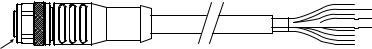
11 Automatic control wiring - standard pump
Interfacing the pump with other devices is by means of two IP66 rated five pole M12 connectors mounted on the front of the pump. M12 connectors with flying lead cables can be purchased as an accessory from Watson-Marlow. The function of each of the leads is labelled.
 Output connection
Input connection
It is the user’s responsibility to ensure the safe and reliable operation of the pump under remote and automatic control.
Never apply mains power to the five pole M12 connectors. Apply the correct signals to the pins, as shown below. Limit signals to the maximum values shown. Do not apply voltage across other terminals. Permanent damage may result.
All input and output terminals are separated from mains circuits by reinforced insulation. These terminals must only be connected to external circuits that are also separated from mains voltages by reinforced insulation as a minimum requirement.
11.1 Input pin assignments at the pump
|
|
|
|
|
|
|
|
|
|
|
|
Pin 2 |
|
|
|
|
|
|
|
|
|
|
|
|
|
Pin 3 |
Pin 1 |
|
|
|
|
|
|
|
|
|
|
|
|
|
|
|||
|
|
|
|
|
|
|
|
|
|
|
|
|||
|
|
|
|
|
|
|
|
|
|
|
|
|||
|
|
|
|
|
|
|
|
|
|
|
|
|||
|
|
|
|
|
|
|
|
|
|
|
|
Pin 5 |
|
|
|
|
|
|
|
|
|
|
|
|
|
|
|
|
|
|
|
|
|
|
|
|
|
|
|
|
|
Pin 4 |
|
|
|
|
|
|
|
|
|
|
|
|
|
|
|
|
|
Pin |
Function |
Specification |
Referenced to |
Input lead |
||||||||||
No. |
|
|
|
|
|
|
|
|
|
|
|
|
|
colour |
1 |
Run/stop |
Min. 5V, max. 30V |
Connect 5–24V DC supply to |
Brown |
||||||||||
|
|
|
|
|
|
|
|
|
|
|
|
stop (referenced to pin 4) |
|
|
|
|
|
|
|
|
|
|
|
|
|
|
Alternatively connect pin 5 of |
|
|
|
|
|
|
|
|
|
|
|
|
|
|
the output connector to this |
|
|
|
|
|
|
|
|
|
|
|
|
|
|
pin via normally open switch |
|
|
2 |
External |
Min. 5V, max. 30V |
Pulse 5–24V |
|
White |
|||||||||
|
contact |
|
|
|
|
|
|
|
|
|
|
40ms minimum pulse length |
|
|
|
|
|
|
|
|
|
|
|
|
|
|
(referenced |
to pin 4) |
|
|
|
|
|
|
|
|
|
|
|
|
|
Alternatively connect pin 5 of |
|
|
|
|
|
|
|
|
|
|
|
|
|
|
the output connector to this |
|
|
|
|
|
|
|
|
|
|
|
|
|
|
pin via normally open switch |
|
|
3 |
4-20mA |
250W input impedence |
Referenced to GND |
Blue |
||||||||||
|
|
40mA max. current |
|
|
|
|||||||||
4 |
GND |
Ground (0V) |
|
|
Black |
|||||||||
5 |
Remote fluid |
Min. 5V, max. 30V |
Connect 5–24V DC supply |
Grey |
||||||||||
|
recovery |
|
|
|
|
|
|
|
|
|
|
to reverse the pump in |
|
|
|
|
|
|
|
|
|
|
|
|
|
|
analog mode |
|
|
Watson-Marlow qdos30 Universal and Universal+ Pump User Manual |
|
17 |
||||||||||||
11.2 Optional input lead
Input lead length: 3m (10ft)


 Brown
Brown

 White
White


 Blue
Blue

 Black
Black


 Grey
Grey
Blue insert
Remote stop
Applying a 5V to 24V signal to pin 1 will STOP the pump in all operating modes. In manual and analogue mode, the pump will start when the signal is removed.
External contact
Digital pulse input min. 5V, min. pulse duration 40ms. This input is used to trigger a user defined dose size. Refer to the contact mode section.
Speed: analog input
The speed of this pump can be controlled remotely by a current analog signal within the range 4-20mA.
The analog signal must be applied to pin three of the M12 input connector. The pump will provide an increasing speed for a rising control signal.
The Universal+ model can be calibrated by the user to control the speed proportionally or inversely proportional to the input mA signal.
4-20mA circuit impedance: 250Ω.
Inverting the response is set up in software. Do not invert the polarity of the terminals. If the polarity is inverted the motor will not run.
Remote fluid recovery
When remote fluid recovery is enabled in fluid recovery settings, the user will be able to reverse the pump remotely by supplying a signal to pin five. This will only work in Analog 4–20mA mode when a 4–20mA signal is received and there is no remote STOP signal.
Watson-Marlow qdos30 Universal and Universal+ Pump User Manual |
18 |

11.3 Output pin assignments at the pump
|
|
|
Pin 2 |
|
|
|
Pin 3 |
Pin 1 |
|
|
|
Pin 5 |
|
|
|
|
|
Pin 4 |
|
Pin |
Function |
Specification |
|
Output |
No. |
|
|
|
lead |
|
|
|
|
colour |
1 |
Run/status |
Open collector output uncommitted |
Brown |
|
|
output |
|
|
|
2 |
Alarm output |
Open collector output uncommitted |
White |
|
3 |
Analog out |
4-20mA into 250Ω (referenced to pin 4) |
Blue |
|
|
|
(Universal+ only) |
|
|
4 |
GND |
|
|
Black |
5 |
Supply |
5V 20mA, this can be connected via a NO |
Grey |
|
|
|
switch to input pin 1 or 2 to power the inputs. |
|
|
Example wiring for a “pull up resistor”
Diagram depicts either Alarm or Run Stop output.
PLC |
qdos |
+24V
1K2 Minimum
2K2 Typical
Input
Common
Example wiring for an external relay, the NO or NC contacts could be used to drive any device.
Diagram depicts either Alarm or Run Status output.
PLC |
qdos |
+24V
2K2 Typical
1K2 Minimum 1A 100V
Common
The resistor or relay needs to be sized correctly to ensure no damage to the pump transistors. These solutions require external 24V power. If connecting to a PLC 24V is usually available.
Watson-Marlow qdos30 Universal and Universal+ Pump User Manual |
19 |
Speed: analog output (Universal+ only)
A current analog signal within the range 4-20mA into 250Ω impedance is available between pin three and pin four of the output connector. The current is fixed and directly proportional to the pumphead rotation speed. 4mA = zero speed; 20mA = maximum speed.
Note: If the mA output is to be used for reading from a multimeter, a 250Ω resistor is required in series.
11.4 Optional output lead
Output lead length: 3m (10ft)


 Brown
Brown

 White
White


 Blue
Blue

 Black
Black


 Grey
Grey
Yellow insert
Watson-Marlow qdos30 Universal and Universal+ Pump User Manual |
20 |
12 Automatic control wiring - module
The pump can be connected with other devices by means of the screw-terminal connectors within the 24 volt relay module situated on the side of the pump. The relay module must be removed from the pump housing to allow suitable cables to be connected to the terminal connectors via the watertight cable glands on the module.
12.1 Module: cover removal and refitting
Removing the 24 volt relay module cover
The module cover is secured to the side of the drive unit by four M3x10 Pozidriv pan head stainless steel screws.
Remove the four screws from the module cover, leaving the top left screw until last. It is possible that the sealing strip may cause the module to adhere to the drive housing. If so, a gentle tap will free it. Do not use a tool to force it off.
The sealing strip should be retained within its channel on the side panel of the drive housing. It ensures ingress protection between the drive housing and the module cover. Check the integrity of the sealing strip. If it is damaged it must be replaced.
Refitting the 24 volt relay module cover
Ensure the sealing strip is undamaged and positioned within its channel on the side of the drive housing. Hold the module cover in place, taking care not to disturb the sealing strip. Starting with the top left screw, tighten the four retaining screws to 2.5Nm.
Ensure that the 24 volt logic module cover is correctly secured at all times by all four screws. Failure to do so may compromise the
IP66 (NEMA 4X) protection.
Watson-Marlow qdos30 Universal and Universal+ Pump User Manual |
21 |

12.2 Wiring up the terminal connectors
It is the user’s responsibility to ensure the pump’s safe and reliable operation under remote and automatic control.
Cable entry to the module is via two watertight cable glands on the module cover.
These may be fitted in place of the sealing plugs which are fitted to the side of the module cover when the pump is shipped.
The number of glands needed depends on the number of connection cables required and the convenience of the installer. As standard, two ½” cable glands are provided with the pump.
Recommended control cable conductors for the terminal blocks: metric = 0.14sq mm - 2.5sq mm solid and 0.14sq mm - 1.5sq mm stranded. USA = 26AWG - 14AWG solid and 26AWG - 16AWG stranded. Cable: circular. Max/min outside diameter to ensure a seal when passed through the standard gland: 9.5mm-12mm. The cable section must be circular to ensure a seal.
For EMC protection, shielded control cable should be used. The shielding should be terminated to either of the provided spade connections.
Cables should have a minimum temperature rating of 85C.
Note: Screened, circular control cable up to 12 core must be used. The cable screen must be earthed at both ends of the cable.
Suitable cables for general-purpose use: 300V with extra premium grade PVC jacket with good flame and moisture resistance.
Suitable cables for industrial use: 300V extra-rugged polyurethane grade jacket with resistance to oils, fuels, solvents and water.
For convenience of wiring more than 8 conductors per cable may be awkward to handle.
•Use a suitable 21mm spanner to unscrew the sealing plugs.
•Screw in the supplied ½” NPT cable glands complete with new sealing washers in place of the plug, ensuring that the retaining nut is properly seated. Tighten the gland to 2.5Nm using a suitable 21mm spanner, to ensure a seal. If a different gland is used, it must be watertight to IP66.
Watson-Marlow qdos30 Universal and Universal+ Pump User Manual |
22 |

•Loosen the gland cap (do not remove it) and pass the cable in through the gland. When it has passed through the gland, continue to push the cable through.
•Pull through sufficient cable to reach the connectors required, leaving a little slack.
• Strip the outer sheath as necessary and remove 5mm of insulation from the conductors. No tinning or ferrule is required. Note: If very stiff or large-diameter cable is used, it may be convenient to strip the outer sheath before passing the cable’s conductors through the gland. However, to ensure a watertight seal, the cable must have an undamaged sheath within the gland when it is tightened.
•Prepare the cable screen(s) by twisting a suitable length. The twisted length(s) shall ideally be sleeved to prevent shorting.
•Secure the end of the cable screen to the Faston receptacles on the spade connectors provided.
•Push the bared conductor into the square hole in the connector. When the conductor is fully inserted, tighten the retaining screw to secure it in place.
Note: If multi-strand wire is used, it must be terminated with a crimp suitable for the wire diameter.
•When all conductors are in position replace the module cover.
•Using a 21mm spanner tighten the gland cap to 2.5Nm to ensure a watertight seal. Alternatively, tighten the gland by hand until it is finger-tight and use a spanner to tighten it further by onehalf a turn.
Ensure that unused openings on the module are sealed using the blanking plugs provided. Failure to do so will result in loss of ingress protection.
Do not strap the control and mains power cables together.
Watson-Marlow qdos30 Universal and Universal+ Pump User Manual |
23 |
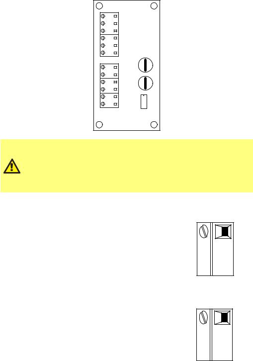
12.3 24 volt relay module pcb connectors
As you look at the module the pcb will appear in the same orientation as shown in the diagram below.
|
N/C |
3 |
|
|
|
RLY1 C |
|
J5 |
|
|
|
|
N/O |
1 |
|
|
|
|
N/C |
3 |
|
|
|
RLY2 C |
|
J4 |
|
|
|
|
N/O |
1 |
|
|
|
|
|
|
|
|
|
|
|
|
|
|
J7 |
Stop/ |
+24V Contact |
1 2 |
J3 |
|
|
-20mA GND |
2 |
J2 |
|
|
|
4 I/P |
1 |
|
|
J6 |
|
|
|
|
|
|
|
4-20mA |
O/P GND |
1 2 |
J1 |
SW1 |
N/C N/O Stop/Contact |
Never apply mains power to the terminals within a qdos30 24V relay module. Apply the correct signals to the terminals shown below. Limit signals to the maximum values shown. Do not apply voltage across other terminals. Permanent damage, not covered by warranty, may result. The maximum load on the relay contacts of this pump is 24VDC at 1.0A. Note that the maximum switching capacity on DC is 30W.
Alarm output (J5)
Connect the output device to the C (common) terminal of the relay connector and either the N/C (normally closed) or N/O (normally open) terminal as required.
This relay coil is energised when the pump has an alarm condition.
Note: Alarm conditions are generated by system errors. This alarm will not be operated for analogue signal errors.
Run status output (J4)
Connect the output device to the C (common) terminal of the relay connector and either the N/C (normally closed) or N/O (normally open) terminal as required.
This relay coil is energised when the pump is running.
RLY1
N/C 3
C 
 2 J5
2 J5
N/O 
 1
1
RLY2
N/C 3
C 
 2 J4
2 J4
N/O 
 1
1
Watson-Marlow qdos30 Universal and Universal+ Pump User Manual |
24 |
 Loading...