


 Loading...
CLS200, MLS300,
and CAS200
Communications
Specification
Watlow Anafaze
Repairs and Returns:
1241 Bundy Blvd.
Winona, MN 55987
Customer Service:
Phone.....800-414-4299
Fax.......... |
800-445-8992 |
Technical Support: |
|
Phone....... |
507-494-5656 |
Fax............. |
507-452-4507 |
Email......... |
wintechsupport@watlow.com |
Part No. 0600-1015-5100. Revision 3.0
November 2003
Copyright © 1996, 1997, 2003
Watlow Anafaze
Information in this manual is subject to change without notice. No part of this publication may be reproduced, stored in a retrieval system, or transmitted in any form without written permission from Watlow Anafaze.
Warranty
Watlow Anafaze, Incorporated warrants that the products furnished under this Agreement will be free from defects in material and workmanship for a period of three years from the date of shipment. The customer shall provide notice of any defect to Watlow Anafaze, Incorporated within one week after the Customer's discovery of such defect. The sole obligation and liability of Watlow Anafaze, Incorporated under this warranty shall be to repair or replace, at its option and without cost to the Customer, the defective product or part.
Upon request by Watlow Anafaze, Incorporated, the product or part claimed to be defective shall immediately be returned at the Customer's expense to Watlow Anafaze, Incorporated. Replaced or repaired products or parts will be shipped to the Customer at the expense of Watlow Anafaze, Incorporated.
There shall be no warranty or liability for any products or parts that have been subject to misuse, accident, negligence, failure of electric power or modification by the Customer without the written approval of Watlow Anafaze, Incorporated. Final determination of warranty eligibility shall be made by Watlow Anafaze, Incorporated. If a warranty claim is considered invalid for any reason, the Customer will be charged for services performed and expenses incurred by Watlow Anafaze, Incorporated in handling and shipping the returned unit.
If replacement parts are supplied or repairs made during the original warranty period, the warranty period for the replacement or repaired part shall terminate with the termination of the warranty period of the original product or part.
The foregoing warranty constitutes the sole liability of Watlow Anafaze, Incorporated and the customer's sole remedy with respect to the products. It is in lieu of all other warranties, liabilities, and remedies. Except as thus provided, Watlow Anafaze, Inc. disclaims all warranties, express or implied, including any warranty of merchantability or fitness for a particular purpose.
Please Note: External safety devices must be used with this equipment.
Contents
Contents
Overview........................................................................ |
1 |
In This Manual ............................................................ |
1 |
Chapter 1: ANAFAZE/AB Protocol............................. |
3 |
Protocol Syntax................................................................. |
3 |
Control Codes.............................................................. |
3 |
Transaction Sequence.................................................. |
4 |
Packet Format.............................................................. |
6 |
Codes in a Packet ........................................................ |
6 |
Error Checking.................................................................. |
8 |
Block Check Character (BCC) .................................... |
8 |
Cyclic Redundancy Check (CRC)............................... |
9 |
Examples........................................................................... |
10 |
Block Read .................................................................. |
10 |
Block Write ................................................................. |
13 |
Message Data .................................................................... |
14 |
Data for a Read Command .......................................... |
14 |
Data for a Write Command ......................................... |
15 |
Two-Byte Data Types ................................................. |
15 |
Figuring Block Size..................................................... |
15 |
Anafaze/AB Data Table Summary.................................... |
16 |
Ordering of Heat and Cool Channel Parameters ......... |
17 |
Ordering of Ramp-Soak Profile Parameters................ |
17 |
Anafaze/AB Protocol Data Table................................ |
17 |
Chapter 2: Modbus-RTU Protocol............................... |
21 |
Overview........................................................................... |
21 |
Transactions on Modbus-RTU Networks ................... |
21 |
The Query-Response Cycle......................................... |
22 |
Serial Transmission ..................................................... |
22 |
Message Framing ........................................................ |
23 |
CRC Error Checking ................................................... |
25 |
Function Codes............................................................ |
26 |
Writing Data ................................................................ |
30 |
Reading Data ............................................................... |
30 |
Examples........................................................................... |
31 |
Read Examples ............................................................ |
31 |
Write Examples ........................................................... |
32 |
Modbus-RTU Data Table Summary.................................. |
33 |
Ordering of Heat and Cool Channel Parameters ......... |
34 |
Ordering of Ramp-Soak Profile Parameters................ |
34 |
Relative and Absolute Modbus Addresses.................. |
35 |
Modbus-RTU Protocol Data Table ............................. |
35 |
Communications Specification i
|
Contents |
Chapter 3: Controller Parameter Descriptions |
........... 39 |
Correlating Menu Items with Parameters ......................... |
39 |
Parameters (by number).................................................... |
45 |
Proportional Band/Gain (0) ......................................... |
45 |
Derivative Term (1)..................................................... |
45 |
Integral Term (2) ......................................................... |
45 |
Input Type (3).............................................................. |
46 |
Output Type (4) ........................................................... |
47 |
Setpoint (5).................................................................. |
48 |
Process Variable (6) .................................................... |
48 |
Output Filter (7) .......................................................... |
48 |
Output Value (8).......................................................... |
49 |
High Process Alarm Setpoint (9) ................................ |
49 |
Low Process Alarm Setpoint (10) ............................... |
49 |
Deviation Alarm Band Value (11) .............................. |
49 |
Alarm Deadband (12).................................................. |
49 |
Alarm_Status (13) ....................................................... |
50 |
Ambient Sensor Readings (15) ................................... |
52 |
Pulse Sample Time (16) .............................................. |
52 |
High Process Variable (17) ......................................... |
52 |
Low Process Variable (18) .......................................... |
52 |
Precision (19) .............................................................. |
53 |
Cycle Time (20) .......................................................... |
54 |
Zero Calibration (21)................................................... |
54 |
Full Scale Calibration (22) .......................................... |
54 |
Digital Inputs (25) ....................................................... |
54 |
Digital Outputs (26) .................................................... |
55 |
Override Digital Input (28) ......................................... |
55 |
Override Polarity (29) ................................................. |
55 |
System Status (30)....................................................... |
56 |
System Command Register (31) ................................. |
56 |
Data Changed Register (32) ........................................ |
57 |
Input Units (33) ........................................................... |
57 |
EPROM Version Code (34) ........................................ |
58 |
Options Register (35) .................................................. |
58 |
Process Power Digital Input (36) ................................ |
59 |
High Reading (37) ....................................................... |
59 |
Low Reading (38)........................................................ |
59 |
Heat/Cool Spread (39)................................................. |
59 |
Startup Alarm Delay (40) ............................................ |
60 |
High Process Alarm Output Number (41)................... |
60 |
Low Process Alarm Output Number (42) ................... |
60 |
High Deviation Alarm Output Number (43) ............... |
60 |
Low Deviation Alarm Output Number (44)................ |
60 |
Channel Profile and Status (46) .................................. |
61 |
Current Segment (47) .................................................. |
62 |
Segment Time Remaining (48) ................................... |
62 |
Current Cycle Number (49)......................................... |
62 |
Tolerance Alarm Time (50)......................................... |
62 |
Communications Specification ii
|
Contents |
Last Segment (51) ....................................................... |
62 |
Number of Cycles (52) ................................................ |
63 |
Ready Setpoint (53)..................................................... |
63 |
Ready Event States (54) .............................................. |
63 |
Segment Setpoint (55)................................................. |
64 |
Triggers and Trigger States (56) ................................. |
64 |
Segment Events and Event States (57)........................ |
65 |
Segment Time (58)...................................................... |
66 |
Tolerance (59) ............................................................. |
66 |
Ramp/Soak Flags (60)................................................. |
66 |
Output Limit (61) ........................................................ |
67 |
Output Limit Time (62)............................................... |
67 |
Alarm_Control (63)..................................................... |
68 |
Alarm_Acknowledge (64)........................................... |
68 |
Alarm_Mask (65) ........................................................ |
68 |
Alarm_Enable (66) ...................................................... |
68 |
Output Override Percentage (67) ................................ |
69 |
AIM Fail Output (68) .................................................. |
69 |
Output Linearity Curve (69)........................................ |
70 |
SDAC Mode (70) ........................................................ |
70 |
SDAC Low Value (71)................................................ |
70 |
SDAC High Value (72) ............................................... |
70 |
Save Setup to Job (73)................................................. |
71 |
Input Filter (74) ........................................................... |
71 |
Loop Alarm Delay (75) ............................................... |
71 |
Loop Names (77)......................................................... |
71 |
T/C Failure Detection Flags (78) ................................ |
72 |
Channel Name (78) ..................................................... |
72 |
Restore PID Digital input (79) .................................... |
72 |
Manufacturing Test (80).............................................. |
72 |
PV Retransmit Primary Loop Number (81) ................ |
73 |
PV Retransmit Maximum Input (82) .......................... |
73 |
PV Retransmit Maximum Output (83)........................ |
73 |
PV Retransmit Minimum Input (84) ........................... |
73 |
PV Retransmit Minimum Output (85) ........................ |
74 |
Cascade Primary Loop Number (86)........................... |
74 |
Cascade Base Setpoint (87)......................................... |
74 |
Cascade Minimum Setpoint (88)................................. |
74 |
Cascade Maximum Setpoint (89) ................................ |
74 |
Cascade Heat/Cool Span (90) ..................................... |
75 |
Ratio Control Master Loop Number (91).................... |
75 |
Ratio Control Minimum Setpoint (92) ........................ |
75 |
Ratio Control Maximum Setpoint (93) ....................... |
75 |
Ratio Control Control Ratio (94) ................................ |
75 |
Ratio Control Setpoint Differential (95) ..................... |
75 |
Loop Status (96) .......................................................... |
76 |
Output Type/Disable (97)............................................ |
76 |
Output Reverse/Direct (98) ......................................... |
76 |
Controller Type (99).................................................... |
77 |
Ramp/Soak Profile Number (100)............................... |
77 |
Communications Specification iii
|
Contents |
Controller Address (101)............................................. |
77 |
Baud Rate (102) .......................................................... |
77 |
Ready Events (103) ..................................................... |
78 |
Appendix A: Communications Driver ......................... |
79 |
Compiling and Linking ............................................... |
79 |
Compatibility............................................................... |
79 |
Commands................................................................... |
79 |
Glossary ........................................................................ |
83 |
Communications Specification iv

Overview
Overview
This reference guide is designed to help applications software programmers with the following tasks:
•Interface to Watlow Anafaze MLS300, CLS200, MLS and CLS controllers, and the CAS200 and CAS scanners via serial communications.
•Modify the communications Anafaze protocol driver in the Watlow Anafaze Communications Driver Kit. (If you have the communications driver kit, you don’t need to read this manual unless you want to modify the communications driver.)
In This Manual
The following sections are included in this guide:
Chapter 1: Anafaze/AB Protocol. Gives an overview and explanation of the Anafaze/Allen Bradley communications protocol.
Chapter 2: Modbus-RTU Protocol. Gives an overview and explanation of the Modbus-RTU communications protocol
Chapters 1 and 2: Data Table Summary. Provides standard controller data table maps for the parameters (one for each protocol).
Chapter 3: Parameters Description. Describes each parameter.
Appendix A: Communications driver.
Glossary: Explanation of commonly used terms and acronyms.
NOTE
This reference guide is not a tutorial. It does not explain how to use the controller; it is not a programming reference; it also does not explain PID control, alarms, linear scaling, or other topics that are explained in detail in the controller manuals. If you need additional information about a topic covered in this reference guide, consult the documentation included with your controller.
Communications Specification 1
Overview
2 Communications Specification

Chapter 1: ANAFAZE/AB Protocol
Chapter 1: ANAFAZE/AB Protocol
This section explains the ANAFAZE/Allen Bradley protocol used in Watlow Anafaze MLS, CLS, and CAS devices. These controllers operate on serial communications links (EIA/TIA-232 or EIA-TIA-485) at either 2400 or 9600 baud. They use 8 data bits, one or 2 stop bits, and no parity.
Protocol Syntax
The controllers use a half-duplex (master-slave) protocol to interface to high-level software. The host software is considered the “master” and the controller is considered the “slave.” In other words, the software can request information from the controller or download information to the controller. The controller can only respond to communications transactions initiated by the host software. The controller cannot initiate communications.
The controller and host software communicate by sending and receiving information in a “packet” format. A packet consists of a sequence of bytes in a specific format; it can be as large as 256 bytes of data. (For more information about packets, see the Packet Format section later in this chapter.)
The numbers in the packet are sent in binary format. However, our examples show bytes in hexadecimal format.
Control Codes
Watlow Anafaze abbreviates control codes this way:
Code |
Meaning |
Decimal |
Hex |
|
Value |
Value |
|||
|
|
|||
|
|
|
|
|
DLE |
Escape code |
16 |
10 |
|
|
Signals the start of the other control code character sequences. |
|
|
|
|
|
|
|
|
STX |
Start Text |
02 |
02 |
|
|
Begins a transmission. |
|
|
|
|
|
|
|
|
ETX |
End Text |
03 |
03 |
|
|
Ends a transmission. |
|
|
|
|
|
|
|
|
ENQ |
Request Resend |
05 |
05 |
|
|
Tells the controller to resend its last ACK or NAK. Host software |
|
|
|
|
sends this command, and the controller responds to it. |
|
|
|
|
|
|
|
Communications Specification 3
Chapter 1: ANAFAZE/AB Protocol
Code |
Meaning |
Decimal |
Hex |
|
Value |
Value |
|||
|
|
|||
|
|
|
|
|
ACK |
Acknowledged |
06 |
06 |
|
|
Signals that a syntactically correct packet has been received. |
|
|
|
|
|
|
|
|
NAK |
Not Acknowledged |
21 |
15 |
|
|
Signals that an incorrect, invalid packet has been received. |
|
|
|
|
|
|
|
Transaction Sequence
Here are the four steps in a transaction between the host software and the controller. The following example shows the transaction as an exchange of packets. The example also assumes that there are no communication errors in the exchange.
(1)The host software sends a packet that contains a read command or write command.
(2)The controller sends a DLE ACK to the host software.
(3)The host software receives a reply packet from the controller.
(4)The host software sends a DLE ACK.
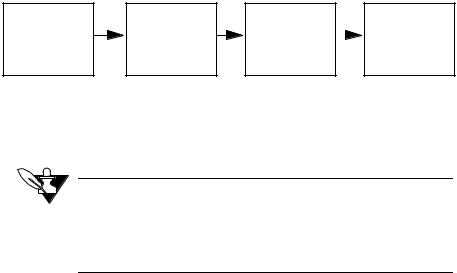
The following flowchart shows a transaction with no error handling.
Send |
Receive |
Receive valid |
|
Send |
command |
|
|||
|
||||
packet |
DLE ACK |
reply packet |
|
DLE ACK |
|
|
|
|
(continued on next page)
NOTE
Due to the difference between the processing speeds of the controller and PCs, it may be necessary to delay the computer's acknowledgement (ACK) in order for the controller to receive it. A delay of 200 ms should suffice.
4 Communications Specification

Chapter 1: ANAFAZE/AB Protocol
This flowchart shows one way for the host software to handle error checking. (If you are writing simple software, you don't necessarily need to use error handling routines as complete as these.)
Send command packet
Wait for DLE ACK or DLE NAK
Send DLE ENQ |
|
NO |
NO |
|
|
YES |
Sent DLE YES |
Sent packet |
YES |
Timed out? |
|
ENQ |
Done |
|
|
3 times? |
|||
|
|
3 times? |
|
|
|
|
|
|
|
NO |
|
|
|
|
Got ACK |
NAK |
|
|
|
or NAK? |
|
|
|
|
ACK |
|
|
|
|
Wait for reply |
|
Send DLE NAK |
|
|
packet |
|
|
|
|
|
|
|
|
|
|
|
NO |
|
|
Timed out? |
YES |
Sent DLE |
YES |
|
|
NAK 3 times? |
|
|
|
|
|
|
|
NO
NO
Packet valid?
YES
Send DLE ACK
Communications Specification 5
Chapter 1: ANAFAZE/AB Protocol
Packet Format
Messages are transmitted in the form of packets. Command and reply packets specify the source and destination addresses, whether to read or write, the block of data to read or write, etc.
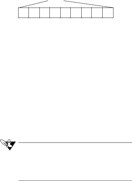
A packet contains a sequence of binary bytes formatted this way:
DLE |
STX |
|
DLE |
ETX |
BCC/CRC |
|
|
|
|
|
|
DST SRC CMD STS TNSL TNSH ADDL ADDH DATA
Sending Control Codes
To send a control code, send a DLE before the control code to distinguish it from data.
Sending a DLE as Data
When you send a byte with an x10, (a DLE), the controller and software interpret it as a command. Therefore, to send a DLE as data, send another DLE immediately before it (DLE DLE).
Codes in a Packet
This section describes the sequence of bytes in a packet, in the order the host software or controller sends them.
DLE STX
•The DLE STX byte signals the beginning of a transmission. Every packet of information starts with the control codes DLE STX.
DST
•The DST byte is the address of the destination device (usually a controller; the first Watlow Anafaze controller is at x08).
NOTE
When host software communicates with an MLS, a CLS, or a CAS in ANAFAZE or AB protocol, it does not send the controller’s actual address. Since the protocol reserves device addresses 0 to 7, the host software sends the value (controller address + 7), instead of the actual device address.
SRC
•The SRC byte is the device address of the packet’s source. The host software is usually designated address x00.
6 Communications Specification
Chapter 1: ANAFAZE/AB Protocol
CMD
•The CMD byte indicates the command that the host software sends to the controller. The software sends a read (x01) or write (x08). When the controller replies, it returns the read or write command with the 7th bit set—in other words, it sends an x41 or x48.
STS (The Status Byte)
•The controller uses the status byte, or STS, to return general status and error flags to the host software. (The controller ignores the status byte in the host software's command packet.) The next table shows status byte values and definitions.
•An “x” in the status bytes below indicates that the associated nibble may contain additional information. In most cases, the status byte is composed of two independent nibbles. Each nibble is independent so that two codes can return at once. For example, status code F1 indicates that data has changed (Fx) and the controller is being updated through the front panel (x1).
Status |
Description |
|
in Hex |
||
|
||
|
|
|
00 |
The controller has nothing to report, or AB protocol is selected. |
|
|
|
|
01 |
Access denied for editing. The controller is being updated through the |
|
|
front panel. |
|
|
|
|
02 |
AIM Comm failure. |
|
|
|
|
A0 |
A controller reset occurred. |
|
|
|
|
Cx |
The controller received a command that was not a block read or block |
|
|
write. (Command Error) |
|
|
|
|
Dx |
The block write command attempted to write beyond a particular parame- |
|
|
ter block boundary, or the host software attempted to access a data table |
|
|
block that does not exist. (Data Boundary Error) |
|
|
|
|
Ex |
The Alarm_Status variable has changed. The software should query the |
|
|
alarm status block to determine the particular alarm flag that changed. |
|
|
|
|
Fx |
The controller altered shared data, either internally (from the firmware) or |
|
|
externally (from the keyboard). The host software should read the Data |
|
|
Changed Register to determine which data has been altered and update |
|
|
its own run-time memory. |
|
|
|
|
|
TNSL |
•Least significant byte of the transaction number. This is the first half of a “message stamp.”
•The controller sends back the TNSL and TNSH exactly as it received them, so host software can use the TNSL and TNSH bytes to keep track of message packets.
TNSH
•Most significant byte of the transaction number. This is the second half of the “message stamp.”
Communications Specification 7

Chapter 1: ANAFAZE/AB Protocol
ADDL
•The low byte of the beginning data table address of the block of data to read or write.
ADDH
•The high byte of the beginning data table address of the block of data to read or write.
DATA
•The new values to be set with a write command, or the requested data in a response to a read command.
DLE ETX
•Every packet of information must end with the codes DLE ETX. These codes signal the end of a transmission.
BCC or CRC
•Communications packets include a oneor two-byte error check at the end of the packet. There are two error check methods: Block Check Character (BCC), which requires 1 byte, and Cyclic Redundancy Check (CRC), which requires 2 bytes.
Error Checking
Watlow Anafaze recommends that you use the default error check method, BCC. It is easier to implement than CRC, and it is acceptable for most applications.
Select one error check method and configure both software and controller for that method, or they will be unable to communicate.
The error check methods work this way:
Block Check Character (BCC)
BCC checks the accuracy of each message packet transmission. It provides a medium level of security. The BCC is the 2’s complement of the 8-bit sum (modulo-256 arithmetic sum) of the data bytes between the DLE STX and the DLE ETX. (1’s complement +1)
•BCC does not detect transposed bytes in a packet.
•BCC cannot detect inserted or deleted 0 values in a packet.
•If you have sent an x10 as data (by sending DLE x10) only one of the DLE data bytes is included in the BCC’s sum (the DLE = x10 also).
8 Communications Specification

Chapter 1: ANAFAZE/AB Protocol
For instance, the block read example shown in the examples section, adds x08 00 01 00 00 80 02 10. Note that the x10 representing DLE has been left out of the calculation. The sum should come to x9B.
1001 1011 = x9B
0110 0100 = 1’s complement
+1 = 2’s complement
0110 0101 = x65
Cyclic Redundancy Check (CRC)
CRC is a more secure error check method than BCC. It provides a very high level of data security. It can detect:
•All single-bit and double-bit errors.
•All errors of odd numbers of bits.
•All burst errors of 16 bits or less.
•99.997% of 17-bit error bursts.
•99.998% of 18-bit and larger error bursts.
The CRC is calculated using the value of the data bytes and the ETX byte. At the start of each message packet, the transmitter must clear a 16-bit CRC register.
When a byte is transmitted, it is exclusive-ORed with the right 8 bits of the CRC register and the result is transferred to the right 8 bits of the CRC register. The CRC register is then shifted right 8 times by inserting 0’s on the left.
Each time a 1 is shifted out on the right, the CRC register is ExclusiveORed with the constant value xA001. After the ETX value is transmitted, the CRC value is sent, least significant byte (LSB) first.
Below is a structured English procedure from AB Manual:
data_byte = all application layer data, ETX CLEAR CRC_REGISTER
FOR each data_byte
GET data_byte
XOR (data_byte, right eight bits of CRC_REGISTER)
PLACE RESULT in right eight bits of CRC_REGISTER
DO 8 times
Shift bit right, shift in 0 at left
IF bit shifted =1
XOR (CONSTANT, CRC_REGISTER)
PLACE RESULT in CRC_REGISTER
END IF
END DO
END FOR
TRANSMIT CRC_REGISTER as 2-byte CRC field
Communications Specification 9

Chapter 1: ANAFAZE/AB Protocol
Examples
The host software sends two kinds of commands: block reads and block writes. This section shows examples of both commands.
 NOTE
NOTE
If you read data from a loop set to SKIP, the controller will send an empty packet for that loop.
This section does not show how to calculate the error check value included with every packet. For help calculating the error check value, see the section on BCC or CRC earlier in this chapter.
Block Read
This example shows the block read command the host software sends, the controller’s responses, and the software's acknowledgment.
Situation: Read process variables for loops 1 to 8.
•8 process variables 2 bytes each = 16 bytes from data table address x0280.
•Character values are represented in hex.
•The sender is device address 0.
•The destination is device address 8 (controller address 1).
•The software sends transaction number 00.
10 Communications Specification

Chapter 1: ANAFAZE/AB Protocol
The next picture shows the read command.
x10 02 08 00 01 00 00 00 80 02 10 10 10 03 65
 BCC value ETX
DLE
Data (number of bytes to upload)
DLE
Data table address (LSB first)
Transaction number
Placeholder for status byte
Command (block read)
SRC (Source Device Address)
DST (Destination Device Address)
STX
DLE
The controller sends a DLE-ACK:
x10 06
 ACK
ACK
DLE
Communications Specification 11

Chapter 1: ANAFAZE/AB Protocol
Then the controller sends its reply:
x10 02 00 08 41 00 00 00 (DATA) 10 03 C3
BCC value
ETX
DLE
Data (see below)
Transaction number
Status (00 = nothing to report)
Command
Source Device Address (controller address + 7)
Destination Device Address
STX
DLE
DATA:
xE2 01 09 02 E4 01 09 02 F1 01 DF 01 28 3C E4 01
Data, transmitted LSB first. Assuming precision for loops is –1:
Loop 1 PV = x01E2 = 482, displayed as 48
Loop 2 PV = x0209 = 521, displayed as 52, etc.
Then the host software sends a DLE-ACK:
x10 06
ACK
DLE
12 Communications Specification

Chapter 1: ANAFAZE/AB Protocol
Block Write
This section describes the block write command.
This example shows the block write command the master sends, the controller's responses, and the master's acknowledgment:
Situation: Write setpoint of 100 to loop 6.
•1 setpoint 2 bytes per setpoint = 2 bytes to address x01CA (x01C0 + xA, a 10-byte offset).
•Character values are represented in hexadecimal.
•The sender is device address 0.
•The destination is device address 8 (controller address 1).
•The software sends transaction number 00.
Here's a picture of the write command:
x10 02 08 00 08 00 00 00 CA 01 E8 03 10 03 3A
BCC value
ETX
DLE
Data: 100 converts to 1000 = x03E8 (assuming the precision for loop 6 is –1)
Data table address
LSB first; x01CA = setpoint for loop Transaction number
Placeholder for status byte
Command (block write)
SRC (Source Device Address)
DST (Destination Device Address)
STX
DLE
The controller sends a DLE-ACK:
x10 06
ACK
DLE
Communications Specification 13

Chapter 1: ANAFAZE/AB Protocol
Here’s a picture of the controller’s reply:
x10 02 00 08 |
48 00 |
00 00 |
10 |
03 |
B0 |
BCC value
ETX
DLE
Transaction number LSB/MSB
Status (00 = Nothing to report)
Command (block write)
Source device address
Destination device address
STX
DLE
Then the host software sends a DLE-ACK:
x10 06
ACK
DLE
Message Data
Some messages contain data. What the data is and how much depends on the command used and the purpose of the message.
Data for a Read Command
For a block read command, the data block consists of one byte that indicates the number of bytes to read (up to 244 bytes of data). The controller sends back a packet with a data block that contains the requested bytes.
14 Communications Specification
Chapter 1: ANAFAZE/AB Protocol
Data for a Write Command
For a block write command, the block contains the bytes to write (up to 242 bytes of data). The controller sends back a message packet without data.
Two-Byte Data Types
For two-byte data types, like process variable and setpoint, the controller or host software sends the data in two-byte pairs with the least significant byte first.
Figuring Block Size
In order to read parameter values, you must know how many bytes to request. Parameter values are stored contiguously such that the setpoints for all the loops are stored together and in loop number order. For example, to read the deviation alarm deadband value for loops one to five, you would read five bytes starting at x05A0. Some parameters, such as setpoint, require two bytes of memory to store. So, for example, if you want to read the setpoint for four loops, you must read eight bytes.
Figure total block size in bytes for most loop parameters this way (do not forget the pulse loop):
(Data Size) * (Number of Loops)
Some parameters have values for both heat and cool. Figure block size for such a parameter this way:
2 * (Data Size) * (Number of Loops)
One exception is the units for each loop. Figure the data size for the units this way:
3 * (Number of Loops)
Parameters that are not loop parameters (like system status, digital inputs, or digital outputs) have specific data sizes. These data sizes are listed in the data table in the next section.
Communications Specification 15

Chapter 1: ANAFAZE/AB Protocol
Anafaze/AB Data Table Summary
Each address holds one byte of data. Each parameter value requires one or two addresses to store depending on the type of data. The table below indicates the number of bytes for each data type. The data type for each parameter is indicated in the tables on the following pages.
Data Type and Symbol |
Data Size |
|
|
Unsigned char (UC) |
1 byte |
|
|
Signed char (SC) |
1 byte |
|
|
Unsigned int (UI) |
2 bytes |
|
|
Signed int (SI) |
2 bytes |
|
|
Because each loop is individually configurable, the number of instances of many parameters depends on the number of loops in the controller. Therefore, the number of bytes for these parameters is listed in the tables on the following pages in terms of the number of loops in the controller.
The storage requirements for some parameters depend on the number of digital inputs or digital outputs in the controller (MAX_DIGIN_BYTES and MAX_DIGOUT_BYTES). The storage of ramp-soak profile parameters depend on the number of profiles (MAX_RSP), the number of segments per profile (MAX_SEG), the number of triggers per segment (MAX_TRIG) and the number of events per segment (MAX_EVENT).
The table below shows the values for each of these factors. Use them to calculate the number of bytes for each parameter.
MAX_CH: |
|
4CLS/CLS204 (4 loops + 1 pulse loop) |
5 |
8CLS/CLS208 (8 loops + 1 pulse loop) |
9 |
16CLS/CLS216/CAS200 (16 loops + 1 pulse loop) |
17 |
16MLS/MLS316 (16 loops + 1 pulse loop) |
17 |
32MLS/MLS332 (32 loops + 1 pulse loop) |
33 |
|
|
MAX_DIGIN_BYTES |
1 |
|
|
MAX_DIGOUT_BYTES |
8 |
|
|
MAX_RSP |
17 |
|
|
MAX_SEG |
20 |
|
|
MAX_TRIG |
2 |
|
|
MAX_EVENT |
4 |
|
|
16 Communications Specification

Chapter 1: ANAFAZE/AB Protocol
Ordering of Heat and Cool Channel Parameters
For parameters that have both heat and cool settings the heat values are stored in the first registers and the cool values are stored in the registers starting at the listed address plus MAX_CH.
NOTE
Data table parameters 46 to 60 and 100 are ramp-soak parameters. They are only used in controllers with the ramp-soak option. Parameters 81 to 95 are enhanced features and only available in controllers with the enhanced features option.
Ordering of Ramp-Soak Profile Parameters
Ramp-soak profile parameters are ordered first by profile, then by segment where applicable. So, for example, the first eight bytes of the Ready Events parameter are the ready segment event states for the first profile (profile A) and the next eight bytes are for profile B and so on. In the case of the segment triggers, the first byte contains the first trigger setting for the first segment of profile A, the second byte contains the settings for the second trigger for the first segment of profile A, the third byte contains the settings for the first trigger for the second segment of profile A and so on.
Anafaze/AB Protocol Data Table
Number |
Description |
Address |
Type |
Number of Bytes |
|
in Hex |
|||||
|
|
|
|
||
|
|
|
|
|
|
0 |
Proportional Band/Gain |
0020 |
UC |
MAX_CH * 2 |
|
|
|
|
|
|
|
1 |
Derivative Term |
0060 |
UC |
MAX_CH * 2 |
|
|
|
|
|
|
|
2 |
Integral Term |
00A0 |
UI |
MAX_CH * 4 |
|
|
|
|
|
|
|
3 |
Input Type |
0120 |
UC |
MAX_CH |
|
|
|
|
|
|
|
4 |
Output Type |
0180 |
UC |
MAX_CH * 2 |
|
|
|
|
|
|
|
5 |
Setpoint |
01C0 |
SI |
MAX_CH * 2 |
|
|
|
|
|
|
|
6 |
Process Variable |
0280 |
SI |
MAX_CH * 2 |
|
|
|
|
|
|
|
7 |
Output Filter |
0340 |
UC |
MAX_CH * 2 |
|
|
|
|
|
|
|
8 |
Output Value |
0380 |
UI |
MAX_CH * 4 |
|
|
|
|
|
|
|
9 |
High Process Alarm Setpoint |
0400 |
SI |
MAX_CH * 2 |
|
|
|
|
|
|
|
10 |
Low Process Alarm Setpoint |
04C0 |
SI |
MAX_CH * 2 |
|
|
|
|
|
|
|
11 |
Deviation Alarm Band Value |
05A0 |
UC |
MAX_CH |
|
|
|
|
|
|
|
12 |
Alarm Deadband |
0600 |
UC |
MAX_CH |
|
|
|
|
|
|
|
13 |
Alarm Status |
0660 |
UI |
MAX_CH * 2 |
|
|
|
|
|
|
|
14 |
Not used |
06A0 |
|
128 |
|
|
|
|
|
|
Communications Specification 17
Chapter 1: ANAFAZE/AB Protocol
Number |
Description |
Address |
Type |
Number of Bytes |
|
in Hex |
|||||
|
|
|
|
||
|
|
|
|
|
|
15 |
Ambient Sensor Readings |
0720 |
SI |
2 |
|
|
|
|
|
|
|
16 |
Pulse Sample Time |
0730 |
UC |
1 |
|
|
|
|
|
|
|
17 |
High Process Variable |
0790 |
SI |
MAX_CH * 2 |
|
|
|
|
|
|
|
18 |
Low Process Variable |
0850 |
SI |
MAX_CH * 2 |
|
|
|
|
|
|
|
19 |
Precision |
0910 |
SC |
MAX_CH |
|
|
|
|
|
|
|
20 |
Cycle Time |
09D0 |
UC |
MAX_CH * 2 |
|
|
|
|
|
|
|
21 |
Zero Calibration |
0A10 |
UI |
2 |
|
|
|
|
|
|
|
22 |
Full Scale Calibration |
0A16 |
UI |
2 |
|
|
|
|
|
|
|
23 |
Not used |
0A1C |
|
4 |
|
|
|
|
|
|
|
24 |
Not used |
0A20 |
|
64 |
|
|
|
|
|
|
|
25 |
Digital Inputs |
0A60 |
UC |
MAX_DIGIN_BYTES |
|
|
|
|
|
|
|
26 |
Digital Outputs |
0A70 |
UC |
MAX_DIGOUT_BYTES |
|
|
|
|
|
|
|
27 |
Reserved |
0A80 |
UC |
MAX_DIGOUT_BYTES |
|
|
|
|
|
|
|
28 |
Override Digital Input |
0AA0 |
UC |
1 |
|
|
|
|
|
|
|
29 |
Override Polarity |
0AC0 |
UC |
1 |
|
|
|
|
|
|
|
30 |
System Status |
0AC8 |
UC |
4 |
|
|
|
|
|
|
|
31 |
System Command Register |
0ACC |
UC |
1 |
|
|
|
|
|
|
|
32 |
Data Changed Register |
0ACE |
UC |
1 |
|
|
|
|
|
|
|
33 |
Input Units |
0AD0 |
UC |
MAX_CH * 3 |
|
|
|
|
|
|
|
34 |
EPROM Version Code |
0BF0 |
UC |
12 |
|
|
|
|
|
|
|
35 |
Options Register |
0BFC |
UC |
1 |
|
|
|
|
|
|
|
36 |
Process Power Digital Input |
0C00 |
UC |
1 |
|
|
|
|
|
|
|
37 |
High Reading |
0C60 |
SI |
MAX_CH * 2 |
|
|
|
|
|
|
|
38 |
Low Reading |
0D20 |
SI |
MAX_CH * 2 |
|
|
|
|
|
|
|
39 |
Heat/Cool Spread |
0DE0 |
UC |
MAX_CH |
|
|
|
|
|
|
|
40 |
Startup Alarm Delay |
0E20 |
UC |
1 |
|
|
|
|
|
|
|
41 |
High Process Alarm Output Number |
0E30 |
UC |
MAX_CH |
|
|
|
|
|
|
|
42 |
Low Process Alarm Output Number |
0E90 |
UC |
MAX_CH |
|
|
|
|
|
|
|
43 |
High Deviation Alarm Output |
0EF0 |
UC |
MAX_CH |
|
|
Number |
|
|
|
|
|
|
|
|
|
|
44 |
Low Deviation Alarm Output Number |
0F50 |
UC |
MAX_CH |
|
|
|
|
|
|
|
45 |
Not used |
0F60 |
|
MAX_CH |
|
|
|
|
|
|
|
46 |
Channel Profile and Status |
1000 |
UC |
MAX_CH |
|
|
|
|
|
|
|
47 |
Current Segment |
1020 |
UC |
MAX_CH |
|
|
|
|
|
|
|
48 |
Segment Time Remaining |
1040 |
UI |
MAX_CH * 2 |
|
|
|
|
|
|
|
49 |
Current Cycle Number |
1080 |
UI |
MAX_CH * 2 |
|
|
|
|
|
|
|
50 |
Tolerance Alarm Time |
10C0 |
UI |
MAX_CH * 2 |
|
|
|
|
|
|
|
51 |
Last Segment |
1100 |
UC |
MAX_CH |
|
|
|
|
|
|
|
52 |
Number Cycles |
1120 |
UC |
MAX_CH |
|
|
|
|
|
|
|
53 |
Ready Setpoint |
1140 |
SI |
MAX_RSP * 2 |
|
|
|
|
|
|
18 Communications Specification
Chapter 1: ANAFAZE/AB Protocol
Number |
Description |
Address |
Type |
Number of Bytes |
|
in Hex |
|||||
|
|
|
|
||
|
|
|
|
|
|
54 |
Ready Event States |
1180 |
UC |
MAX_RSP * |
|
|
|
|
|
MAX_DIGOUT_BYTES |
|
|
|
|
|
|
|
55 |
Segment Setpoint |
1280 |
SI |
MAX_RSP * 2 * |
|
|
|
|
|
MAX_SEG |
|
|
|
|
|
|
|
56 |
Triggers and Trigger States |
1780 |
UC |
MAX_RSP* |
|
|
|
|
|
MAX_SEG* |
|
|
|
|
|
MAX_TRIG |
|
|
|
|
|
|
|
57 |
Segment Events and Event States |
1C80 |
UC |
MAX_RSP * MAX_SEG |
|
|
|
|
|
* MAX_EVENT |
|
|
|
|
|
|
|
58 |
Segment Time |
2680 |
UI |
MAX_RSP * 2 * |
|
|
|
|
|
MAX_SEG |
|
|
|
|
|
|
|
59 |
Tolerance |
2B80 |
SI |
MAX_RSP * 2 * |
|
|
|
|
|
MAX_SEG |
|
|
|
|
|
|
|
60 |
Ramp/Soak Flags |
3080 |
UC |
MAX_CH |
|
|
|
|
|
|
|
61 |
Output Limit |
3200 |
SI |
MAX_CH * 4 |
|
|
|
|
|
|
|
62 |
Output Limit Time |
3280 |
SI |
MAX_CH * 4 |
|
|
|
|
|
|
|
63 |
Alarm_Control |
3300 |
UI |
MAX_CH * 2 |
|
|
|
|
|
|
|
64 |
Alarm_Acknowledge |
33C0 |
UI |
MAX_CH * 2 |
|
|
|
|
|
|
|
65 |
Alarm_Mask |
3480 |
UI |
MAX_CH * 2 |
|
|
|
|
|
|
|
66 |
Alarm_Enable |
3540 |
UI |
MAX_CH * 2 |
|
|
|
|
|
|
|
67 |
Output Override Percentage |
3600 |
SI |
MAX_CH * 4 |
|
|
|
|
|
|
|
68 |
AIM Failure Output |
3690 |
UC |
1 |
|
|
|
|
|
|
|
69 |
Output Linearity Curve |
3700 |
UC |
MAX_CH * 2 |
|
|
|
|
|
|
|
70 |
SDAC Mode |
3740 |
UC |
MAX_CH * 2 |
|
|
|
|
|
|
|
71 |
SDAC Low Value |
3780 |
SI |
MAX_CH * 4 |
|
|
|
|
|
|
|
72 |
SDAC High Value |
3800 |
SI |
MAX_CH * 4 |
|
|
|
|
|
|
|
73 |
Save Setup to Job |
3880 |
UC |
1 |
|
|
|
|
|
|
|
74 |
Input Filter |
3890 |
UC |
MAX_CH |
|
|
|
|
|
|
|
75 |
Loop Alarm Delay |
38D0 |
UI |
MAX_CH * 2 |
|
|
|
|
|
|
|
76 |
Not used |
3990 |
|
16 |
|
|
|
|
|
|
|
77 |
Loop Names |
39A0 |
UI |
MAX_CH * 2 |
|
|
(CLS/CLS200 and MLS/MLS300) |
|
|
|
|
|
|
|
|
|
|
78 |
T/C Failure Detection Flags |
3A30 |
UC |
MAX_CH |
|
|
(CLS/CLS200 and MLS/MLS300) |
|
|
|
|
|
|
|
|
|
|
78 |
Channel Name |
3994 |
UC |
MAX_CH * 8 |
|
|
(CAS/CAS200) |
|
|
|
|
|
|
|
|
|
|
79 |
Restore PID Digital Input |
4130 |
UC |
MAX_CH |
|
|
|
|
|
|
|
80 |
Manufacturing Test |
4160 |
UI |
1 |
|
|
|
|
|
|
|
81 |
PV Retransmit Primary Loop |
4200 |
UC |
MAX_CH * 2 |
|
|
Number |
|
|
|
|
|
|
|
|
|
|
82 |
PV Retransmit Maximum Input |
4250 |
UI |
MAX_CH * 4 |
|
|
|
|
|
|
|
83 |
PV Retransmit Maximum Output |
42E0 |
UC |
MAX_CH * 2 |
|
|
|
|
|
|
Communications Specification 19
Chapter 1: ANAFAZE/AB Protocol
Number |
Description |
Address |
Type |
Number of Bytes |
|
in Hex |
|||||
|
|
|
|
||
|
|
|
|
|
|
84 |
PV Retransmit Minimum Input |
4330 |
UI |
MAX_CH * 4 |
|
|
|
|
|
|
|
85 |
PV Retransmit Minimum Output |
43C0 |
UC |
MAX_CH * 2 |
|
|
|
|
|
|
|
86 |
Cascade Primary Loop Number |
4410 |
UC |
MAX_CH |
|
|
|
|
|
|
|
87 |
Cacade Base Setpoint |
4440 |
SI |
MAX_CH * 2 |
|
|
|
|
|
|
|
88 |
Cacade Minimum Setpoint |
4490 |
SI |
MAX_CH * 2 |
|
|
|
|
|
|
|
89 |
Cascade Maximum Setpoint |
44E0 |
SI |
MAX_CH * 2 |
|
|
|
|
|
|
|
90 |
Cascade Heat/Cool Span |
4530 |
UI |
MAX_CH * 4 |
|
|
|
|
|
|
|
91 |
Ratio Control Master Loop Number |
45C0 |
UC |
MAX_CH |
|
|
|
|
|
|
|
92 |
Ratio Control Minimum Setpoint |
45F0 |
SI |
MAX_CH * 2 |
|
|
|
|
|
|
|
93 |
Ratio Control Maximum Setpoint |
4640 |
SI |
MAX_CH * 2 |
|
|
|
|
|
|
|
94 |
Ratio Control Control Ratio |
4690 |
UI |
MAX_CH * 2 |
|
|
|
|
|
|
|
95 |
Ratio Control Setpoint Differential |
46E0 |
SI |
MAX_CH * 2 |
|
|
|
|
|
|
|
96 |
Loop Status |
4730 |
UC |
MAX_CH |
|
|
|
|
|
|
|
97 |
Output Type/Disable |
4760 |
UC |
MAX_CH * 2 |
|
|
|
|
|
|
|
98 |
Output Reverse/Direct |
47B0 |
UC |
MAX_CH * 2 |
|
|
|
|
|
|
|
99 |
Controller Type |
47F0 |
UC |
1 |
|
|
|
|
|
|
|
100 |
Ramp/Soak Profile Number |
4800 |
UC |
MAX_CH |
|
|
|
|
|
|
|
101 |
Controller Address |
4830 |
UC |
1 |
|
|
|
|
|
|
|
102 |
Baud Rate |
4840 |
UC |
1 |
|
|
|
|
|
|
20 Communications Specification

Chapter 2: Modbus-RTU Protocol
Chapter 2: Modbus-RTU Protocol
Overview
Transactions on Modbus-RTU Networks
Standard Modbus-RTU ports use an EIA/TIA-232C- or EIA/TIA-485/ 422-compatible serial interface that defines connector pinouts, cabling, signal levels, transmission baud rates, and parity checking.
Controllers communicate using a master-slave technique, in which only one device (the master) can initiate transactions (called “queries”). The other devices (slaves) respond by supplying the requested data to the master, or by taking the action requested in the query. Typical master devices include host processors and programming panels.
The master can address individual slaves, or initiate a broadcast message to all slaves. Slaves return a message (called a “response”) to queries that are addressed to them individually. Responses are not returned to broadcast queries from the master.
The Modbus-RTU protocol establishes the format for the master’s query by placing into it the device (or broadcast) address, a function code defining the requested action, any data to be sent, and an error-checking field. The slave’s response message is also constructed using ModbusRTU protocol. It contains fields confirming the action taken, any data to be returned, and an error-checking field. If an error occurred in receipt of the message, or if the slave is unable to perform the requested action, the slave will construct an error message and send it as its response.
Communications Specification 21
Chapter 2: Modbus-RTU Protocol
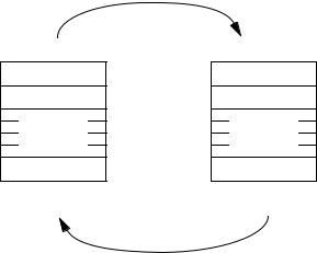
The Query-Response Cycle
Query Message from Master
Device Address
Function Code
8-Bit
Data Bytes
Error Check
Device Address
Function Code
8-Bit
Data Bytes
Error Check
Response Message from Slave
The Query
The function code in the query tells the addressed slave device what kind of action to perform. The data bytes contain any additional information that the slave will need to perform the function. For example, function code 03 will query the slave to read holding registers and respond with their contents. The data field must contain the information telling the slave which register to start at and how many registers to read. The error check field provides a method for the slave to validate the integrity of the message contents.
The Response
If the slave makes a normal response, the function code in the response is an echo of the function code in the query. The data bytes contain the data collected by the slave, such as register values or status. If an error occurs, the function code is modified to indicate that the response is an error response, and the data bytes contain a code that describes the error. The error check field allows the master to confirm that the message contents are valid.
Serial Transmission
Each 8-bit byte in a message contains two 4-bit hexadecimal characters. This high character density allows better data throughput than ASCII for the same baud rate. Each message must be transmitted in a continuous stream.
Coding System
•8-bit binary, hexadecimal 0 to 9, A to F
•2 hexadecimal characters contained in each 8-bit field of the message
Bits per Byte
• 1 start bit
22 Communications Specification
Loading...