


998
Table of contents
 Loading...
Series 998
Dual Channel, 1/8 DIN, Microprocessor-Based
Temperature/Process Controller
0600-0010-000 Rev G
February 2000
Supersedes: W998-XUMN Rev F
$10.00
Made in the U.S.A.
Printed on Recycled Paper 10% Postconsumer Waste
User’s Manual
Watlow Controls
1241 Bundy Boulevard, P.O. Box 5580, Winona, Minnesota USA55987-5580
Phone: (507) 454-5300, Fax: (507) 452-4507 http://www.watlow.com
User Levels:
• New User........................... go to Introduction
• Experienced User................... go to page 4.1
• Expert User............................. go to page 4.1
Installers:
• Set-up..................................... go to page 1.1
• Installation & Wiring ................go to page 2.1
CUS
CTI
TOTAL
CUS
TOMER
SATISFACTI
3 Year Warranty
ON
ISO 9001
Registered Company
Winona, Minnesota USA

Using the Manual
NOTE:
Details of a “Note”
appear here in the
narrow box on the
outside of each
page.
CAUTION:
Details of a
“Caution” appear
here in the narrow
box on the outside
of each page.
WARNING:
Details of a
“Warning”appear
here in the narrow
box on the outside
of each page.
Safety Information
We use note, caution and warning symbols throughout this book to draw
your attention to important operational and safety information.A bold text
“NOTE” marks a short message in the margin to alert you to an important
detail.
A bold text “CAUTION” safety alert appears with information that is
important for protecting your equipment and performance. Be especially
careful to read and follow all cautions that apply to your application.
A bold text “WARNING” safety alert appears with information that is
important for protecting you, others and equipment from damage. Pay
very close attention to all warnings that apply to your application.
The safety alert symbol, ç, (an exclamation point in a triangle) precedes
a general CAUTION or WARNING statement.
Technical Assistance
If you encounter a problem with your Watlow controller, review all of your
configuration information for each step of the setup to verify that your
selections are consistent with your applications.
If the problem persists, an Application Engineer can discuss your application with you.
Before calling, please have the complete model number and user’s manual available. You can get technical support by dialing 507/494-5656, 7
a.m. to 7 p.m. Central Standard Time.
Your Feedback
Your comments or suggestions on this manual are welcome, please send
them to: Technical Writer, Watlow Controls, P.O. Box 5580, Winona, MN
55987-5580, Phone: (507) 454-5300, Fax: (507) 452-4507. The Series
998 User’s Manual is copyrighted by Watlow Winona, Inc., © February
2000, with all rights reserved. (1832)

Table of Contents
Introduction
Starting Out with the Watlow Series 998
i The Series 998
ii Display Loop
ii Operation Menus
iii Setup Menus
iii Factory Menus
Chapter 1
Hardware Setup
1.1 DIP Switch Locations and Functions
1.2 Input Type DIP Switches
1.3 External Power Supply DIP Switches
1.4 Setting the Lockout DIP Switch
Chapter 2
Installation and Wiring
2.1 Panel Cutout and Dimensions
2.2 Installing the Series 998
2.4 Wiring the Series 998
2.4 Power Wiring
2.4 Sensor Installation Guidelines
2.5 Event Input 1 Wiring
2.5 Wiring 0-20mA and 4-20mA
Process Inputs
2.6 Wiring Example
2.7 Wiring Notes
2.8 Channel A Input Wiring
2.9 Channel B Input Wiring
2.10 Channel A Output Wiring
2.11 Channel B Output Wiring
2.12 Output 3 Wiring
2.13 Output 4 Wiring
Chapter 5
The Operation Menus
5.1 Navigating the Operation Menus
5.2 The System Menu
5.3 The Set Point Menu
5.3 System Prompts
5.8 PID A Menu
5.13 PID B Menu
Chapter 6
The Factory Menus
6.1 Navigating the Factory Menus
6.2 Panel Lockout Menu
6.8 Diagnostics Menu
6.14 Calibration Menu
Chapter 7
Tuning, Manual Operation, Alarms and
Error Codes
7.1 Auto-tuning (Heat and/or Cool)
7.2 Manual Tuning
7.3 Manual and Automatic Operation
7.4 Changing the Output 3 Alarm Jumper
7.4 Using Alarms
7.6 Error Code E1 and E2 Messages
7.7 Error Code Actions
Chapter 8
Applications
8.1 Burst Fired, Zero Cross Output
8.2 Retransmit
8.3 Dead Band
8.3 Transmitter Power Supply
Chapter 3
Keys and Displays
3.1 Keys and Displays
3.2 Display Key and Loop
Chapter 4
The Setup Menus
4.1 Navigating the Setup Menus
4.2 Input Menu
4.16 Output Menu
4.32 Global Menu
Appendix
A.1 Warranty and Returns
A.2 Glossary
A.5 Index
A.7 Prompt Index
A.8 Specifications
A.9 Ordering Information
A.10 Declaration of Conformity
WATLOW Series 998 User’s ManualTable of Contents

Notes
Table of ContentsWATLOW Series 998 User’s Manual
WATLOW Series 998 User’s Manual i
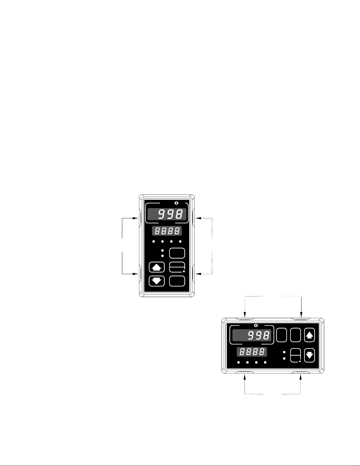
Introduction
Starting Out With the Watlow Series 998
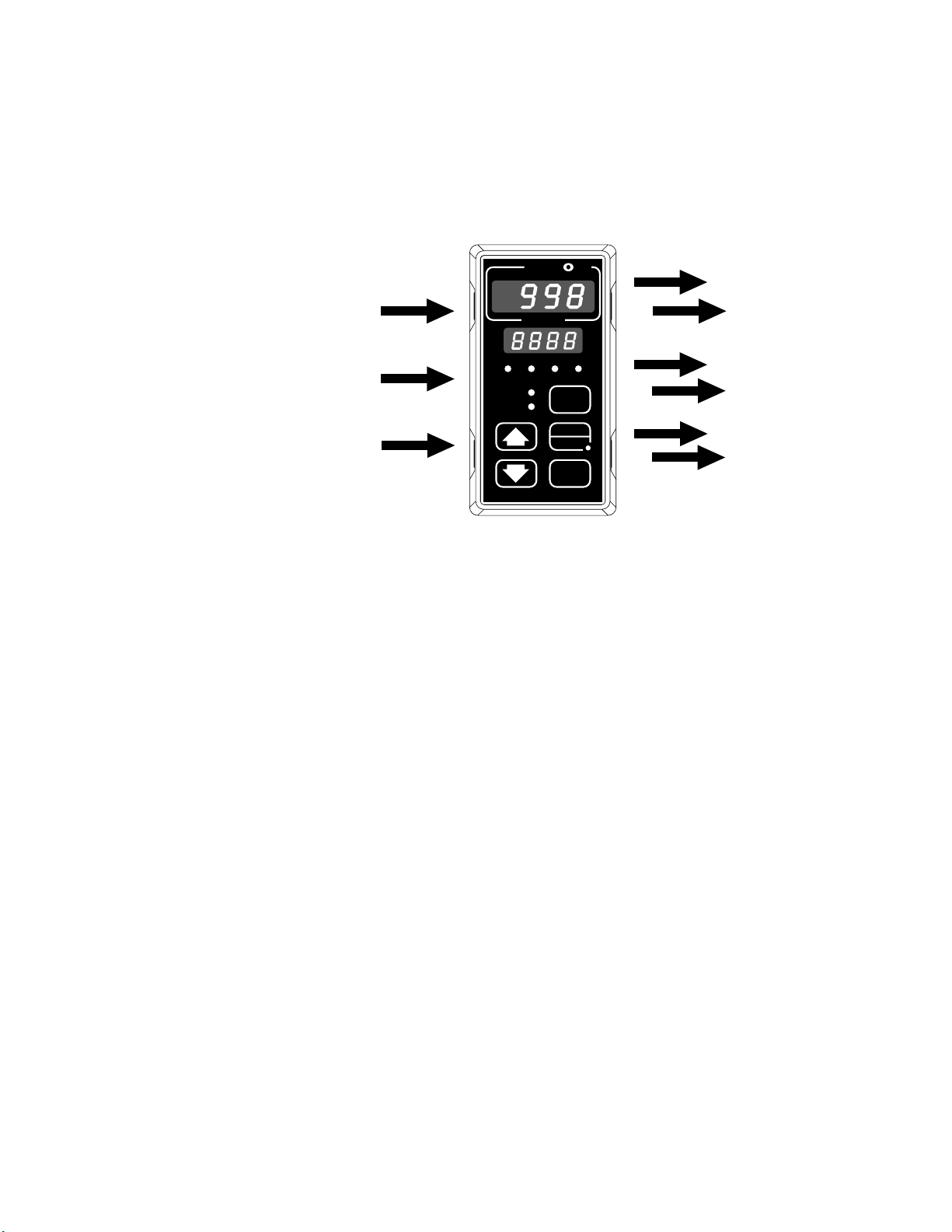
Figure i The Series 998.
TL
W
W
A
PROCESS
1A 2A 1B 2B
CH A
CH B
DISPLAY
SERIES 998
MODE
AUTO
MAN
Channel A Control Outputs
(Output 1A and 2A)
Channel B Control Outputs
(Output 1B and 2B)
Optional Outputs 3 and 4
(alarms, retransmit or
PC communications)
Channel A Input
(Input 1)
Channel B Input
(Input 2)
Event Input
Watlow’s Series 998 process controller is capable of two independent
channels of process control. Each channel can be configured and tuned
separately. Each alarm option (outputs 3 and 4) can be used to trigger an
alarm based on either channel. The retransmit option, available on output
3, can be used to retransmit the process or set point value of either channel. The digital communications option can be used to configure and
monitor the controller with a personal computer from a remote location.
If you are unfamiliar with general controller operation, it’s a good idea to
read through the entire manual. The manual is organized in setup order,
with chapters on wiring, menus, operation and applications. If you understand the concept of process/temperature controls and feel comfortable
skipping around through the manual, use the black tabs at the top of
each page to quickly scan the pages and find the topic needed. The Menu
Overview on the next page is a great place to start. Also, refer to Chapter
3 for information on the keys and displays.
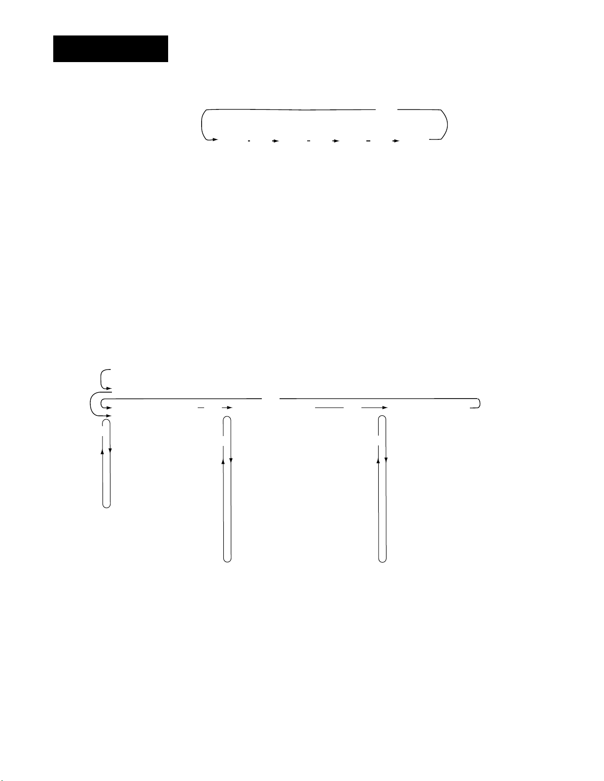
The menu map is an overview of all menus and prompts and how to navigate between them. There are three main menu sets: Setup menus
[`SEt]; Operation menus [OPEr]; and Factory menus [Fcty]. You can
return to the Display Loop from anywhere by pressing the Display key.
DIP switch locations and settings are explained later in Chapter 1.
Introduction
Introduction
Introduction
ii WATLOW Series 998 User’s Manual
From the Display Loop, press the Mode key µ to reach the Operation
menus.
To return to the Display Loop from any point in any menu, press the
Display key ∂.
From the Display Loop, press both the Up-arrow and Down-arrow keys
> and < for three seconds to reach the Setup menus. Hold them
down for another three seconds to reach the Factory menus.
Display Loop
Operation Menus
[`998]
[SP2A]
Set Point 2A
[`998]
[`SyS]
µ
[SP2b]
[OPEr]
[Ei1S]
[Ot3S]
[Ot4S]
[A3LO]
[A3HI]
[A4LO]
[A4HI]
[`AUt]
Set Point 2B
System Menu
Operation Menus
Event Input 1 Status
Output 3 Status
Output 4 Status
Alarm 3 Low
Alarm 3 High
Alarm 4 Low
Alarm 4 High
Auto-tune
µ
Channel A
Process
[`75]
[100]
Channel A
Set Point
[PiDA]
[Oper
[PB1A]
[rE1A]
[It1A]
[rA1A]
[dE1A]
[Ct1A]
[Pb2A]
[rE2A]
[It2A]
[rA2A]
[dE2A]
[Ct2A]
[db`A]
Channel B
Process
∂
[`80]
[125]
Channel B
Set Point
∂
>
PID A Menu
Operation Menus
Output 1 Proportional Band A
Output 1 Reset A
Output 1 Integral A
Output 1 Rate A
Output 1 Derivative A
Output 1 Cycle Time A
Output 2 Proportional Band A
Output 2 Reset A
Output 2 Integral A
Output 2 Rate A
Output 2 Derivative A
Output 2 Cycle Time A
Dead Band A
Channel A
Process
[`75]
[`80]
Channel B
Process
>>
∂
∂
µ
[```]
[`°F]
Process
Units
[PiDb]
[OPEr]
[Pb1b]
[rE1b]
[It1b]
[RA1b]
[dE1b]
[Ct1b]
[Pb2b]
[rE2b]
[It2b]
[rA2b]
[dE2b]
[Ct2b]
[db`b]
PID B Menu
Operation Menus
Output 1 Proportional Band B
Output 1 Reset B
Output 1 Integral B
Output 1 Rate B
Output 1 Derivative B
Output 1 Cycle Time B
Output 2 Proportional Band B
Output 2 Reset B
Output 2 Integral B
Output 2 Rate B
Output 2 Derivative B
Output 2 Cycle Time B
Dead Band B
Introduction
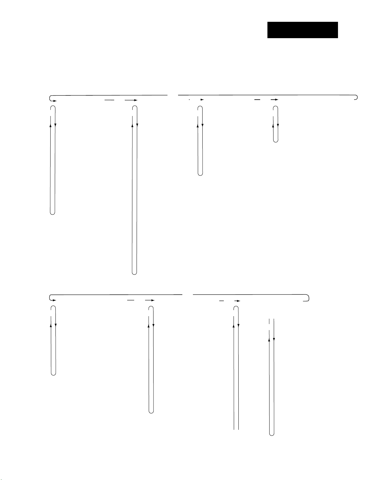
WATLOW Series 998 User’s Manual iii
Introduction
From the Setup menus, press both the Up-arrow and Down-arrow keys > and
< for three seconds to reach the Factory menus.
To return to the Display Loop from any point in any menu, press the Display key
∂.
Setup Menus
[InPt]
[`SEt]
µ µ
[`In1]
[dEC1]
[`rL1]
[`rH1]
[CAL1]
[rtd1]
[Ftr1]
[`In2]
[dEC2]
[`rL2]
[`rH2]
[CAL2]
[rtd2]
[Ftr2]
[Lin2]
[`Alt]
Input Menu
Setup Menus
Input 1
Decimal 1
Range Low 1
Range High 1
Calibration Offset 1
RTD Calibration Curve 1
Input 1 Software Filter
Input 2
Decimal 2
Range Low 2
Range High 2
Calibration Offset 2
RTD Calibration Curve 2
Input 2 Software Filter
Input 2 Linearization
Altitude
>
[OtPt]
[`SEt]
[Ot1A]
[HY1A]
[Ot2A]
[HY2A]
[PrcA]
[Ot1b]
[HY1b]
[Ot2b]
[HY2b]
[Prcb]
[`Ot3]
[`Al3]
[HYS3]
[LAt3]
[SIL3]
[`Ot4]
[`AL4]
[HYS4]
[LAt4]
[SIL4]
[Aout]
[Prc3]
[`ArL]
[`ArH]
[ACAL]
>
Output Menu
Setup Menus
Output 1A
Hysteresis 1A
Output 2A
Hysteresis 2A
Process A
Output 1B
Hysteresis 1B
Output 2B
Hysteresis 2B
Process B
Output 3
Alarm 3
Hysteresis 3
Latching 3
Silencing 3
Output 4
Alarm 4
Hysteresis 4
Latching 4
Silencing 4
Analog Output
Process 3
Retransmit Low Limit
Retransmit High Limit
Retransmit Calibration Offset
>
[gLbl]
[`Set]
µ µ
[`C_F]
[FAIL]
[`err]
[`Ei1]
[Anun]
[AtSP]
[rP`A]
[rt`A]
[rP`b]
[rt`b]
Global Menu
Setup Menus
Celsius-Fahrenheit
Failure Mode
Error Latching
Event Input 1
Annunciator
Auto-tune Set Point
Ramping Channel A
Ramp Rate Channel A
Ramping Channel B
Ramp Rate Channel B
>
[COM]
Communications Menu
[`SEt]
Setup Menus
[bAUd]
Baud Rate
[dAtA]
Data Bits and Parity
[Prot]
Protocol Type
[Addr]
Address
[IntF]
Interface Type
Factory Menus
[PLOC]
[Fcty]
µ
[`LOC]
[`SYS]
[PidA]
[Pidb]
[InPt]
[OtPt]
[gLbL]
[COM]
[diAg]
[`CAL]
Panel Lockout Menu
Factory Menus
User Lockout
System Menu Lockout
PID A Menu Lockout
PID B Menu Lockout
Input Menu Lockout
Output Menu Lockout
Global Menu Lockout
Communications Menu Lockout
Diagnostics Menu Lockout
Calibration Menu Lockout
>
[diAg]
[Fcty
µ µ
[dAtE]
[SOFt]
[Sn--]
[AMb]
[`gnd]
[`rEF]
[cnt1]
[cnt2]
[itY1]
[ity2]
[OtY1]
[OtY2]
[OtY3]
[OtY4]
[dISP]
[tout]
Diagnostics Menu
Factory Menus
Factory Ship Date
Software Revision
Serial Number
Ambient Temperature
Ground A/D Count
Ambient A/D Count
Input 1 A/D Count
Input 2 A/D Count
Input 1 Module
Input 2 Module
Output 1 Module
Output 2 Module
Output 3 Module
Output 4 Module
Test Displays
Test Outputs
>
[`CAL]
>
[Fcty]
[A`50]
[A`00]
[``tc]
[a`OH]
[A`20]
[A`15]
[A380]
[A10U]
[A`OU]
[A20A]
[A`4A]
[A`Ou]
[A100]
[b`50]
[b`00]
[b`OH]
[b`20]
[b`15]
Calibration Menu
Factory Menus
[b380]
[b10U]
µ
[b`OU]
[b`4A]
[b`Ou]
[b100]
[1`4`]
[1`20]
[1`10]
[110`]
[2`4`]
[2`20]
[2`0`]
[2`10]
[3`LO]
[3`HI]
[`rSt]
[`dFL]
Restore Factory Values
Default Prompts

iv WATLOW Series 998 User’s Manual
Notes
Introduction
Chapter 1 Hardware Setup
DIP Switch Locations and Functions
The Watlow Series 998 has at least one and as many as six dual in-line
package (DIP) switches inside the controller, depending on the model
number. They allow users to configure the controller for a variety of input
sensors, to provide power for external signal conditioners or to lockout
front panel access to some functions.
To set any DIP switch:
• Remove the controller from the case by pressing firmly on the two release
tabs on one side or the top of the bezel until they unsnap. Then firmly
press the two release tabs on the opposite side or the bottom of the
control until they unsnap. You will need to gently rock the bezel back
and forth to release it from the chassis.
• Use the illustrations on the following pages to locate and set each DIP switch.
Figure 1.1 - Press
the release tabs to
remove the controller chassis.
Release
Tabs
A
W
PROCESS
1A 2A 1B 2B
CH A
CH B
SERIES 998
W
TL
DISPLAY
AUTO
MAN
MODE
Release
Tabs
W
A
TL
W
PROCESS
1A 2A 1B 2B
Release
Tabs
CH A
CH B
DSPY
MODE
AUTO
MAN
SERIES 998
Hardware Setup, Chapter 1
Release
Tabs
WATLOW Series 998 User’s Manual 1.1
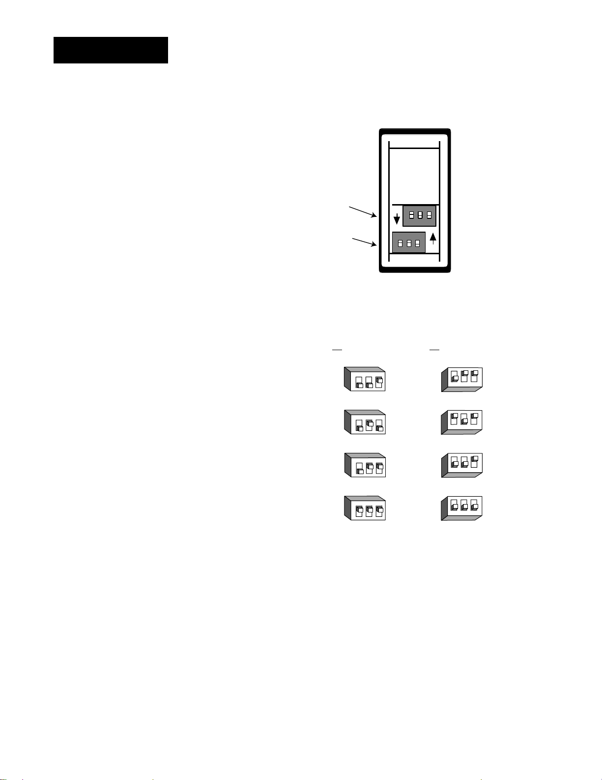
DIP Switches
˜
NOTE:
The input 2 DIP
switch is mounted
upside down.
˜
1 - Set the input DIP
switches to match the
sensors you are using
in your application.
Only controllers with
model number 99__22__-____ have input
DIP switches.
Input 2 DIP
(Channel B)
DIP
Input 1 DIP
(Channel A)
DIP
ON
ON
Controller Chassis
Rear View
Input 1 (Channel A) Input 2 (Channel B)
(99__-2___-____) (99__-_2__-____)
NOTE:
Only controllers
with the indicated
model numbers
have these DIP
switches.
Figure 1.2 Input DIP switches.
RTD
thermocouple: R, S or B
thermocouple: J, K, T, N, E, C, D, Pt2
0-20 or 4-20mA; 0-5, 1-5 or 0-10V
123
O
N
↑
123
O
N
↑
123
O
N
↑
123
O
N
↑
↑
N
O
123
↑
N
O
123
↑
N
O
123
↑
N
O
123
1.2 WATLOW Series 998 User’s Manual
Hardware Setup, Chapter 1
NOTE:
For other voltages
or current settings
contact the factory.
NOTE:
Only controllers
with the indicated
model numbers
have these DIP
switches.
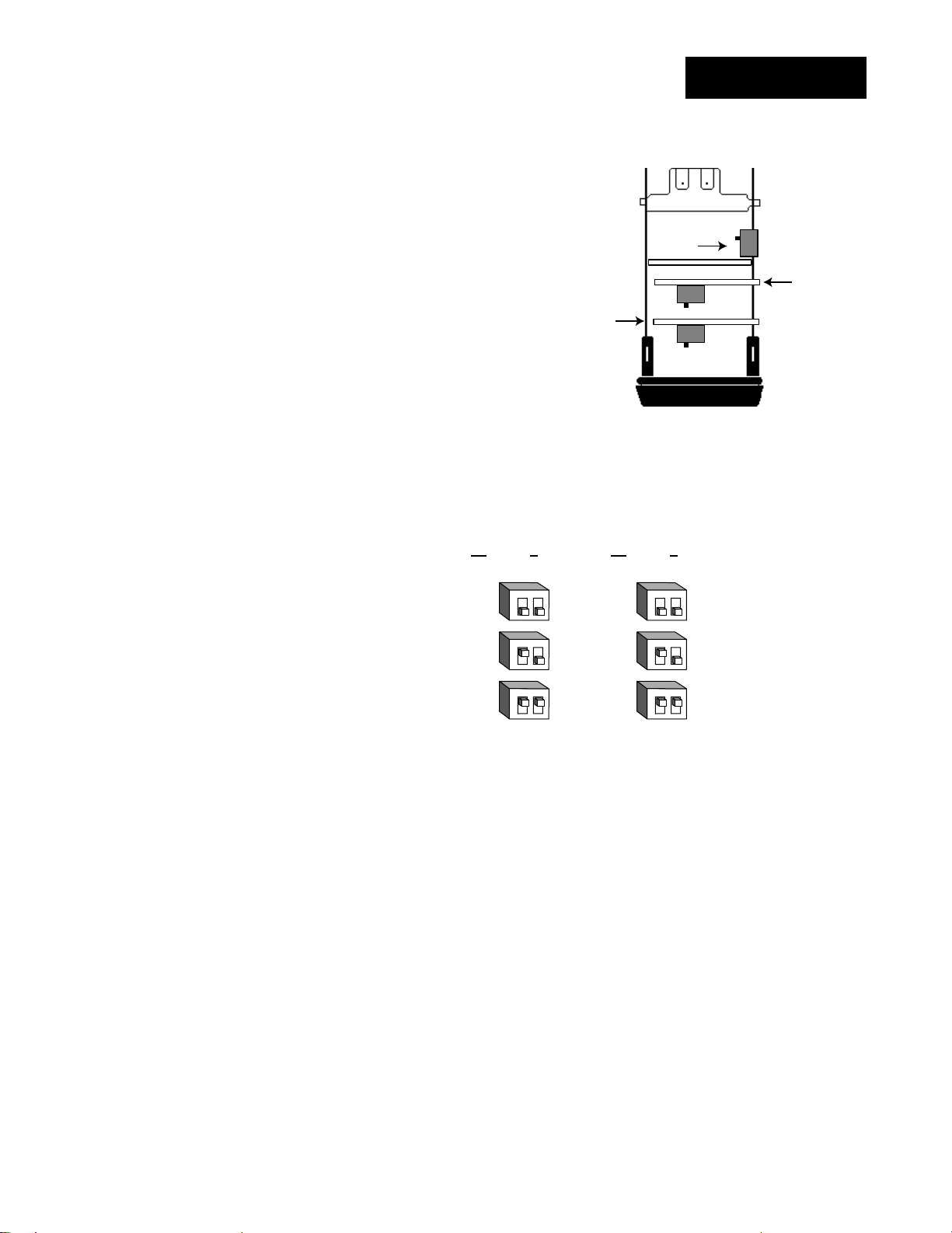
2 - Set DIP switches for
outputs equipped with
an external signal
conditioner power
supply. Only controllers
with model number
99__-____-T___ or
99__-____-_T__ have an
external signal conditioner power supply.
(99
DIP Switches
Lockout
DIP
Output 3
Option Board and Dip
Control Chassis
Top View (996 & 998)
Left-side View (997 & 999)
Output 3 Output 4
__-____-T___) (99__-____-_T__)
ON
OFF
ONOFF
ONOFF
Output 4
Option Board and Dip
Figure 1.3 External signal conditioner power supply DIPs.
12
O
N
↑
12
O
N
↑
12
O
N
↑
20V ± 5% @ 30mA
12V ± 5% @ 30mA
5V ± 5% @ 30mA
12
O
N
↑
12
O
N
↑
12
O
N
↑
3 - When the DIP switches are set, gently insert the controller chassis into
the case and push it firmly into place until all four tabs snap into place.
Hardware Setup, Chapter 1
WATLOW Series 998 User’s Manual 1.3
DIP Switches
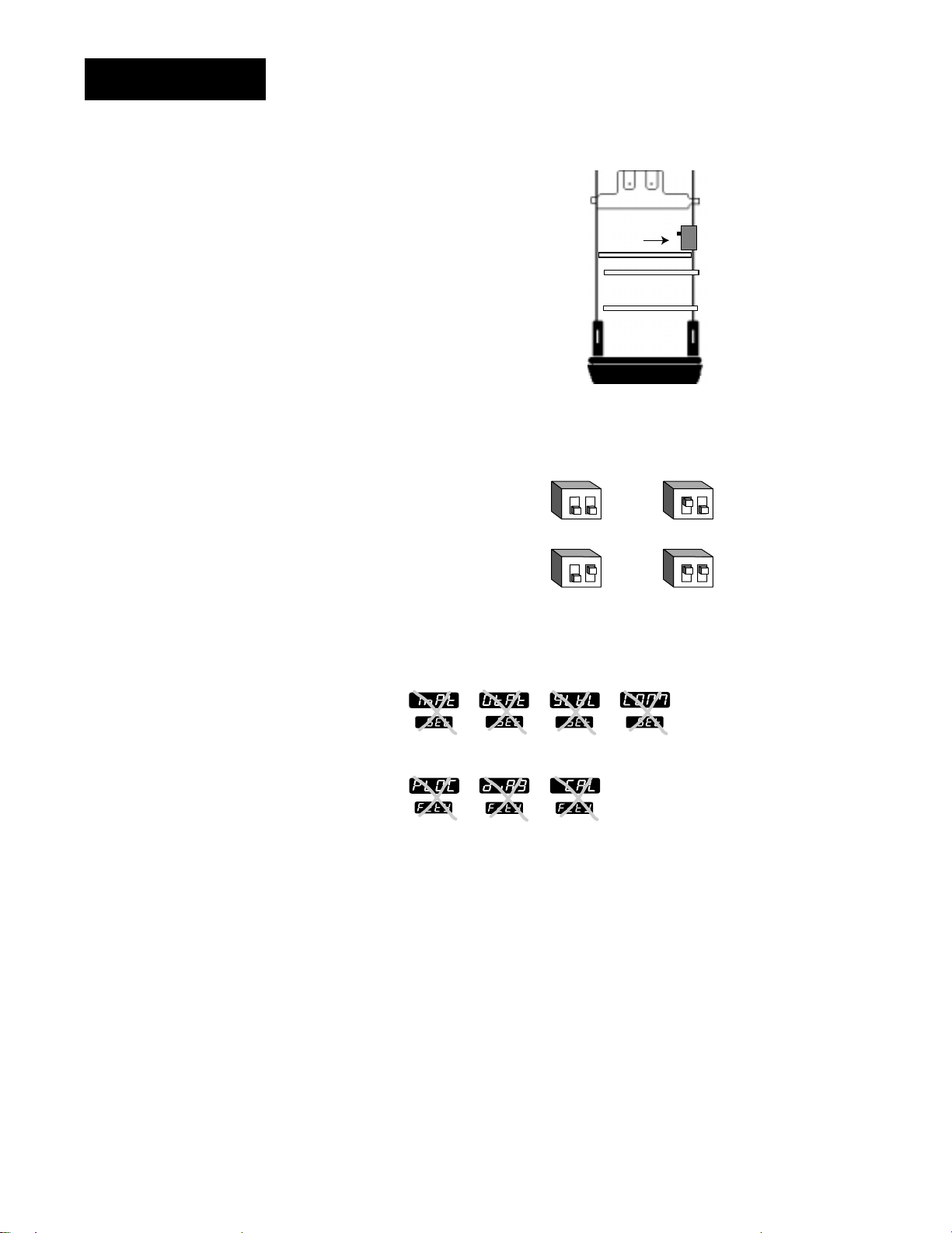
ç
CAUTION:
The lockout DIP
switch makes the
Setup and Factory
menus unavailable.
Configure all the
Setup and Factory
menus before locking them out.
Failure to do so
could result in damage to equipment in
the event of a setup
error.
4 - The lockout DIP switch
hides the Setup Menus (Input,
Output, Global and
Communications) and the
Factory Menus (Panel
Lockout, Diagnostics and
Calibration). All units have a
lockout DIP switch.
All controllers leave the
factory with both switches set
to off.
Lockout
DIP
Control Chassis
Top View (996 & 998)
Left-side View (997 & 999)
ON
OFF
Figure 1.4 Lockout DIP switch.
12
O
N
no hardware lockout or
↑
(Switch 1 has no effect.)
12
O
N
lockout Setup and Factory menus or
↑
(Switch 1 has no effect.)
Input
Panel
Lockout
Output Global
Diagnostics Calibration
Communications
12
O
N
↑
12
O
N
↑
1.4 WATLOW Series 998 User’s Manual
Hardware Setup, Chapter 1
TLTL
W
W
A
PROCESS
1A 2A 1B 2B
CH A
CH B
DISPLAY
SERIES 998
MODE
AUTO
MAN
4.03"
(102mm)
2.18"
(55mm)
TL
W
W
A
PROCESS
CH A
CH B
MODE
SERIES 998
DSPY
AUTO
MAN
1A 2A 1B 2B
4.03"
(102mm)
2.18"
(55mm)
Chapter 2 Installation and Wiring
NOTE:
A minimum of 1.66”
(42.2mm) spacing
between panel
cutouts is recommended.
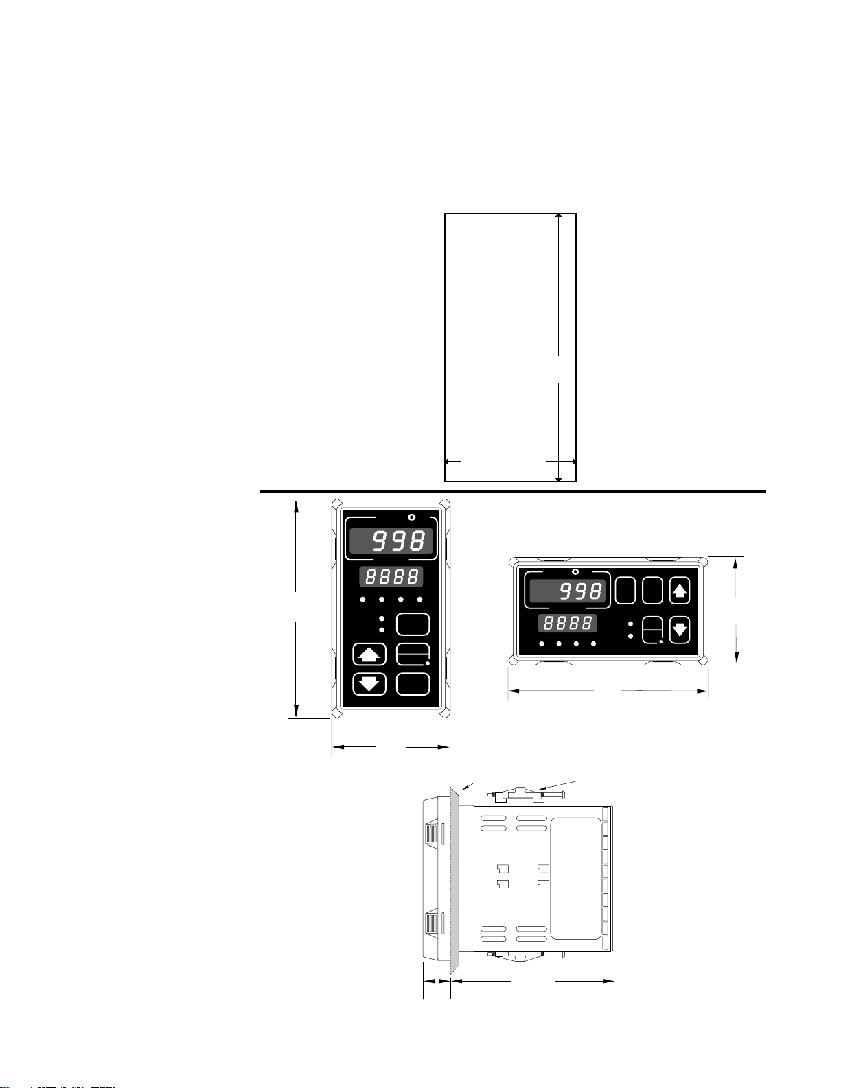
Figure 2.1a Series 998
Panel Cutout
Dimensions.
Panel Cutout
Maximum Panel
Thickness
0.38" (9.65mm)
3.62" + 0.03 -0.00
(92mm + 0.8)
1.77 + 0.02 -0.00
(45mm + 0.6)
NOTE:
Adjustable mounting brackets can
also be side mounted.
Figure 2.1b Series 998
Dimensions.
Installation and Wiring, Chapter 2
0.68"
(17 mm)
Panel
4.06"
(103 mm)
Adjustable
Mounting Bracket
WATLOW Series 998 User’s Manual 2.1
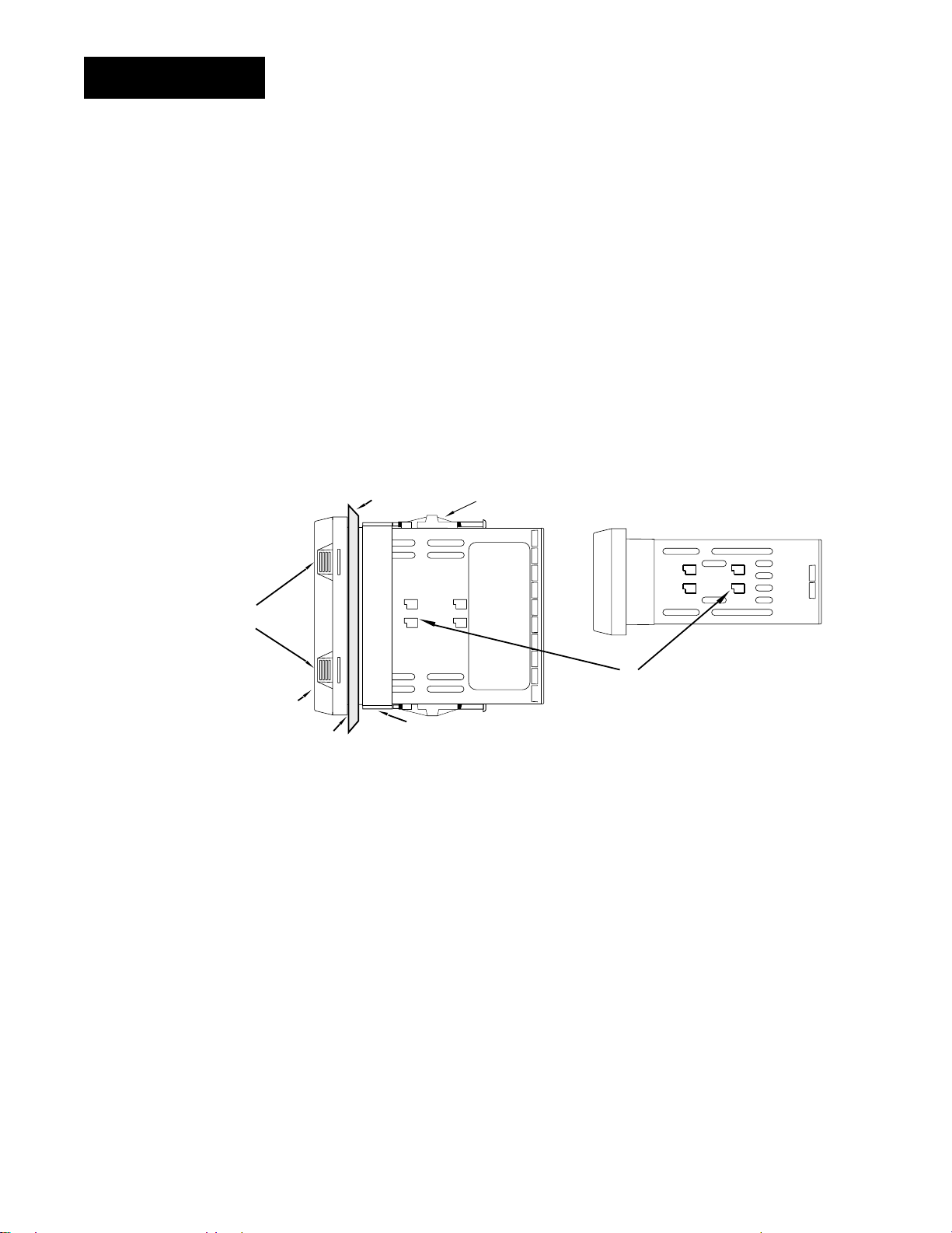
Installing
Panel
Adjustable
Mounting Bracket
Bezel
External Gasket
Mounting Collar
Release Tabs
Top and Bottom (996 or 998)
or Side (997 or 999) View
Mounting Slots
Side (996 or 998)
or Top and Bottom (997 or 999) View
˜
Installing the Series 998
Installing and mounting requires access to the back of the panel.
NOTE:
Removing the controller chassis from
its case makes
mounting easier.
Figure 2.2 Side and top view.
1. Make a panel cutout.
2. To remove the controller chassis from its case, press in firmly on the two
tabs on one side or the top of the bezel until they unsnap, then unsnap
the two tabs on the opposite side or the bottom. Pull the chassis out of
the case by gently rocking it.
3. Slide the case into the panel cutout. Check to see that the gasket is
not twisted, and is seated within the case bezel flush with the panel.
Slide the mounting collar over the back of the control.
2.2 WATLOW Series 998 User’s Manual
Installation and Wiring, Chapter 2

ç
CAUTION:
Follow the installation procedure
exactly to guarantee a proper NEMA
4X seal. Make sure
the gasket between
the panel and the
rim of the case is
not twisted and is
seated properly.
Failure to do so
could result in damage to equipment.
Installing
4. Loosen the mounting bracket screws enough to allow for the mounting
collar and panel thickness. Place each mounting bracket into the
mounting slots (head of the screw facing the back of the controller).
Push each bracket backward then down to secure it to the control
case. To guarantee a proper NEMA 4X seal, Series 996 and 998
units (vertical) must have the mounting brackets located on either
side of the unit. When installing Series 997 and 999 units (horizontal) the brackets must be on the top and bottom of the unit.
5. Make sure the case is seated properly. Tighten the installation screws
firmly against the mounting collar to secure the unit. To ensure a
NEMA 4X seal, there should be no space between the bezel and
panel. Overtightening the screws will distort the case and make it diffi-
cult to remove or replace the controller.
6. Insert the controller chassis into its case and press the bezel until all
four tabs snap. Make sure the inside gasket is seated properly and not
twisted.
7. To release the mounting brackets, loosen the mounting bracket screws
and push the brackets forward, then pull it up and out.
Installation and Wiring, Chapter 2
WATLOW Series 998 User’s Manual 2.3
Wiring
Fuse
22
21
Earth Ground
11
L2L1
ç
WARNING:
To avoid potential
electric shock, use
National Electric
Code (NEC) safety
practices when
wiring and connecting this unit to a
power source and
to electrical sensors or peripheral
devices. Failure to
do so could result
in injury or death.
NOTE:
Input-to-output isolation is defeated
when the external
signal conditioner
power supply is
used to power a
transmitter connected to input 1 or
input 2.
Wiring the Series 998
Wiring options depend on the model number and DIP switch settings.
Check the terminal designation stickers on either side of the controller
and compare your model number to those shown here and with the
model number breakdown on the inside back cover of this manual.
Input-to-output Isolation
The Series 998 uses optical isolation between the analog inputs and the
controller outputs/digital input. This isolation provides a 500VÅ (ac) barrier to prevent ground loops when using grounded sensors and/or
peripheral equipment.
Here is a breakdown of the isolation barriers:
• Analog inputs 1 and 2 are grouped together.
• Outputs 1 through 4 and the standard event input are grouped together. This does not apply to Output 4 when configured as communications.
• The digital communications output (4) is separate from the above
groups.
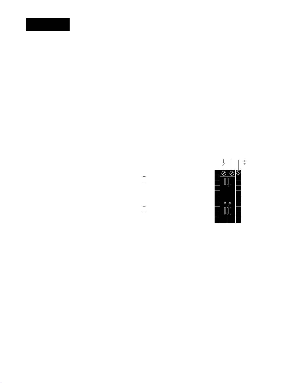
Power Wiring
100 to 240VÅÅ(ac) nominal, (85 to 264 actual)
Vertical Package 99 8
Horizontal Package 99 9
24 to 28 V‡‡(ac/dc) nominal, (20 to 30 actual)
_ - _ _ _ _ - _ _ _ _
_ - _ _ _ _ - _ _ _ _
Figure 2.4 Power wiring.
ç
CAUTION:
The Series 998 will
not function with
two grounded thermocouple inputs.
Avoid using a
grounded thermocouple for both
input 1 and input 2.
Failure to follow
this guideline could
result in damage to
equipment.
Vertical Package 99 6
_ - _ _ _ _ - _ _ _ _
Horizontal Package 99 7 _ - _ _ _ _ - _ _ _ _
Sensor Installation Guidelines
Thermocouple input: Extension wire for thermocouples must be of the
same alloy as the thermocouple itself to limit errors.
Using grounded thermocouples for both input 1 and input 2 may create
ground loop problems. To correct this problem, replace at least one of the
grounded thermocouples with an ungrounded thermocouple. If the application requires grounded thermocouples, use an isolated transmitter,
such as a Watlow Gordon 5702 isolated transmitter.
RTD input: Each 1Ω of lead wire resistance can cause a +2°F error when
using a two-wire RTD. A three-wire RTD sensor overcomes this problem.
All three wires must have the same electrical resistance (i.e., same gauge,
same length, multi-stranded or solid, same metal).
Maintain isolation between input 1 and input 2 to prevent a ground loop.
A ground loop may cause incorrect readings, dashes across the upper
display or the display of error codes.
Process input: Isolation must be maintained between input 1 and input
2. If both input 1 and input 2 are used as process inputs, a separate
power supply and transmitter must be used for each input. Output
option T (external signal conditioner power supply) can be used to supply
power for only one input.
2.4 WATLOW Series 998 User’s Manual
Installation and Wiring, Chapter 2
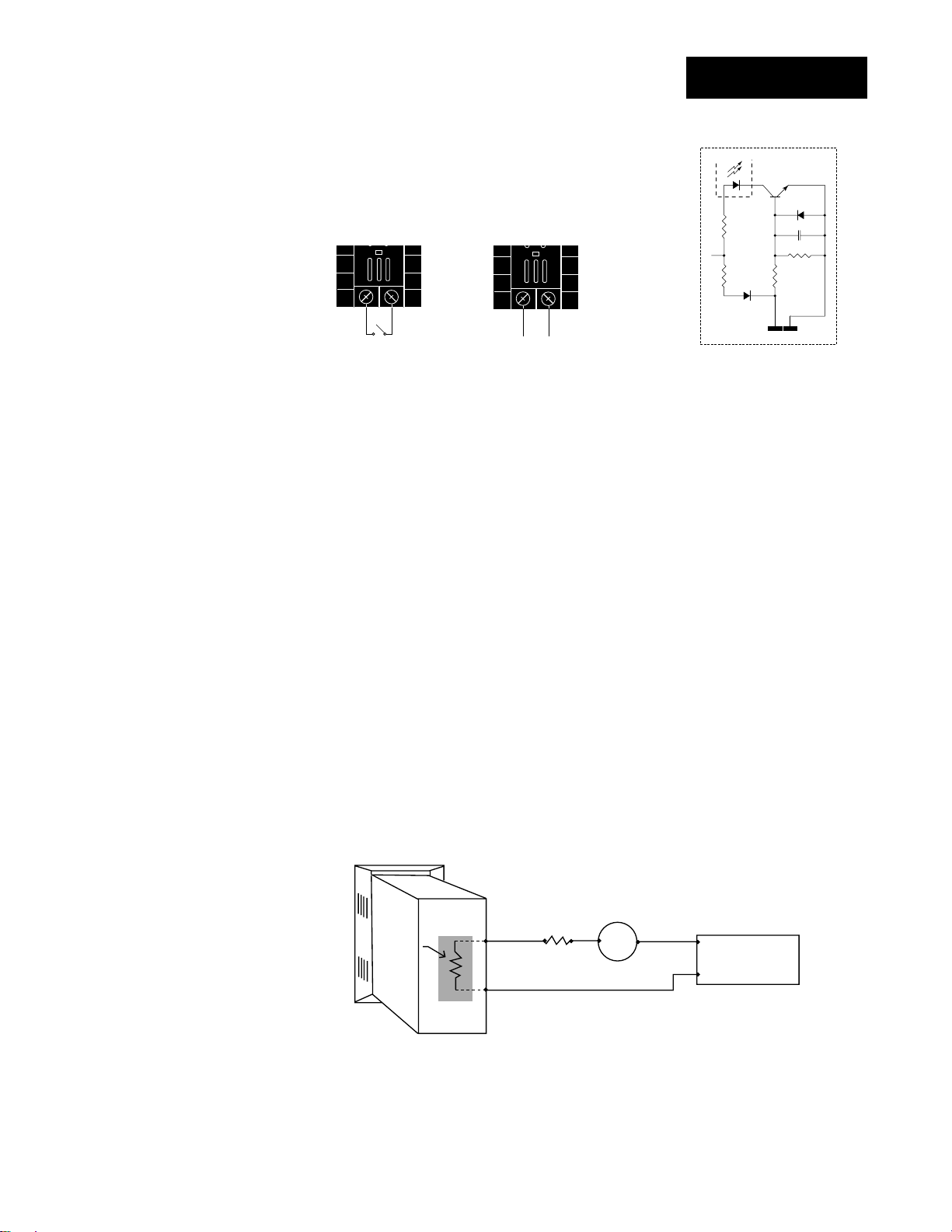
24
23
+24VÎ (dc)
10KΩ
4.99KΩ
OPTO
ISOLATOR
750Ω
.01µf
4.99KΩ
Internal Circuitry
Wiring
23 24
23 24
+
-
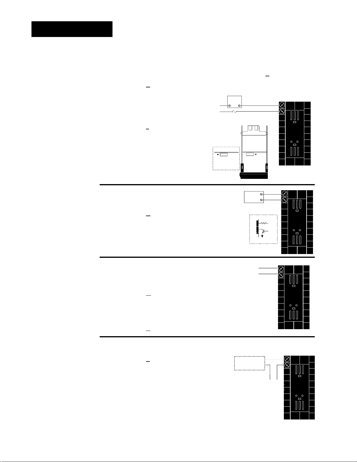
Event Input 1
Standard on all units
14 - 36VÎ (dc) Event Input 1 off (open)
0 - 3VÎ (dc) Event Input 1 on (closed)
OR
Wiring 0-20 and 4-20mA Process Inputs
Certain “transmitters” used in process input applications are producing
internal resistor failures in the Watlow Series 988 family of controllers.
This is only apparent with the Series 988 family 1/8 DIN units with
Process Inputs selected (0-20mA or 4-20mA dc only).
We are noticing that an external resistor is required to prevent a high
in-rush current which burns out the Series 988 family controllers’ 7-ohm
internal resistor. This high in-rush current occurs initially on “power-up.”
If the transmitter turns full on for a split second during power-up, the
available current weakens or damages the internal resistor.
Example: 20V / 7 ohms = 2,857mA (too much!).
The wiring diagram example below shows an application where a cus-
tomer is using a 4-20mA dc transmitter and power supply to feed the
input of a Series 988 controller. The Rx range (100 to 400 ohms) for the
external resistor is recommended. We suggest starting with 250 ohms.
Example: Customer is using a 24VÎ (dc) power supply to power up the
4-20mA dc transmitter that inputs to the Series 988 terminals 8 (-) and 10
(+). To figure out what the internal Series 988’s handling current is for the
0-20mA or 4-20mA dc input to the Series 988 controllers, we need to apply
Ohm’s Law: The square root of Watts divided by Resistance equals Current.
Applying that formula to the example below produces the following: Square
Root of (0.125 Watts / 7 ohms) = 134 mA dc (handling input current). This
is the acceptable input current for the Series 988 universal input board.
988 Process
Input Control
Figure 2.5 Process wiring
example.
Installation and Wiring, Chapter 2
4-20mA dc
Transmitter
R
Internal
Resistor
7Ω
1/8 Watt
+
—
x
100 to 400
ohms
—
+
+
24VÎ (dc)
Power Supply
—
Reminder, the input impedance of 7 ohms handles the majority of our
customer applications; the external resistor (Rx) is only for certain transducers/transmitters that spike on power-up or power-down. Please make
sure your customer’s transmitter / transducer fall within our Series 988
family (1/8 DIN) of controllers’ Process Input specification of 7 ohms
input impedance.
WATLOW Series 998 User’s Manual 2.5
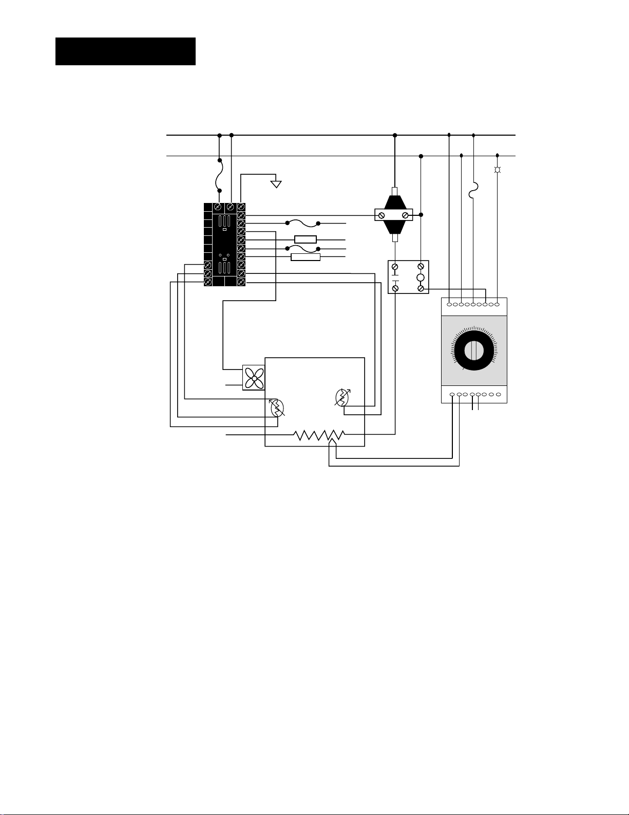
Wiring Example
➥
Series 146
Limit Control
146E-1601-3000
HighTemperature
Light
High-Limit
Mechanical
Control
Fuse
Mercury
Relay
Humidify
Dehumidify
Earthground
Fuse
L1
L2
L1
L2
12
13
14
15
16
17
18
19
20
8
9
10
21 22 11
Coil
123456789
10 11 12 131415 16 17
CNONC
Reset
L2
L2
L1
L2
L1
L2
Heater
Cooling
Fan
Wet Bulb
RTD Sensor
Dry Temp
RTD Sensor
Limit Sensor
Environmental
Chamber
Figure 2.6 System Wiring
Examples.
ç
WARNING:
To avoid potential
electric shock, use
National Electric
Code (NEC) safety
practices when
wiring and connecting this unit to a
power source and
to electrical sensors
or peripheral
devices. Failure to
do so could result
in injury or death.
ç
CAUTION:
To avoid damage to
property and equipment, use National
Electric Code (NEC)
standard wiring
practices to install
and operate the
series 998. Failure
to do so could
result in such damage.
2.6 WATLOW Series 998 User’s Manual
Installation and Wiring, Chapter 2
ç
WARNING:
To avoid damage to
property and equipment, and/or injury
or loss of life, use
National Electric
Code (NEC) standard wiring practices to install and
operate the Series
998. Failure to do so
could result in such
damage, and/or
injury or death.
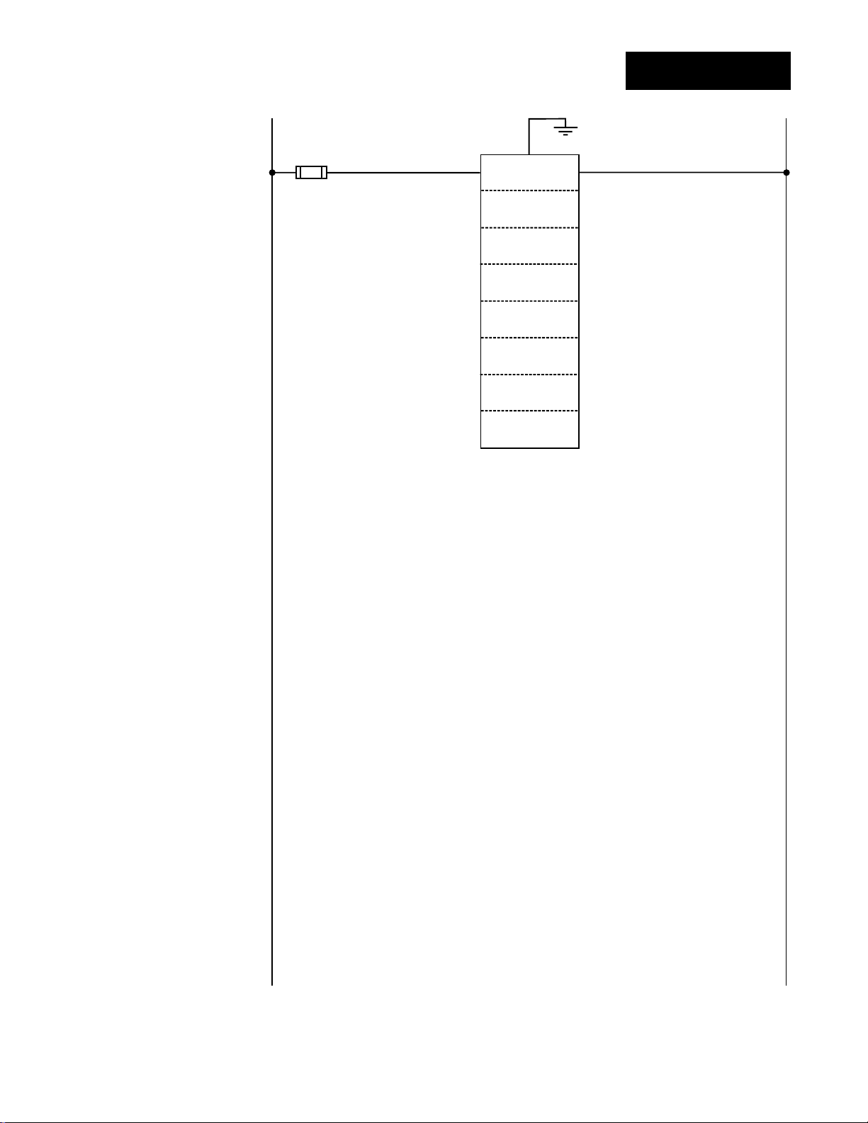
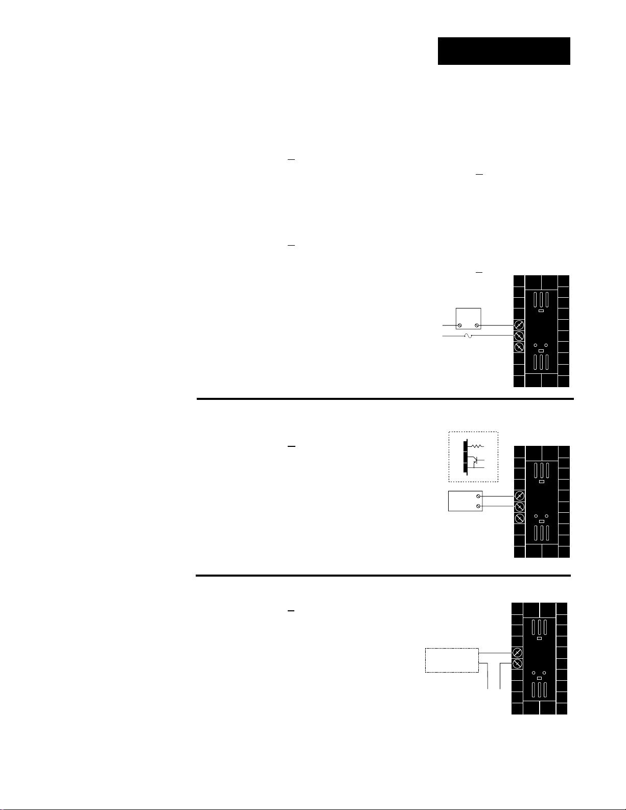
Wiring Notes
L1 L2
earth ground
11
21 22
power
NOTE:
Sketch in your
application on this
page or a copy of
it. See wiring examples in this chapter
and in the Appendix.
Figure 2.7 Wiring notes.
Installation and Wiring, Chapter 2
WATLOW Series 998 User’s Manual 2.7

9
10
+
-
9
10
8
S2
S1
S3
9
10
8
S2
S1
10
9-+
V
DC
O
N
↑
123
O
N
↑
123
O
N
↑
123
O
N
↑
123
O
N
↑
123
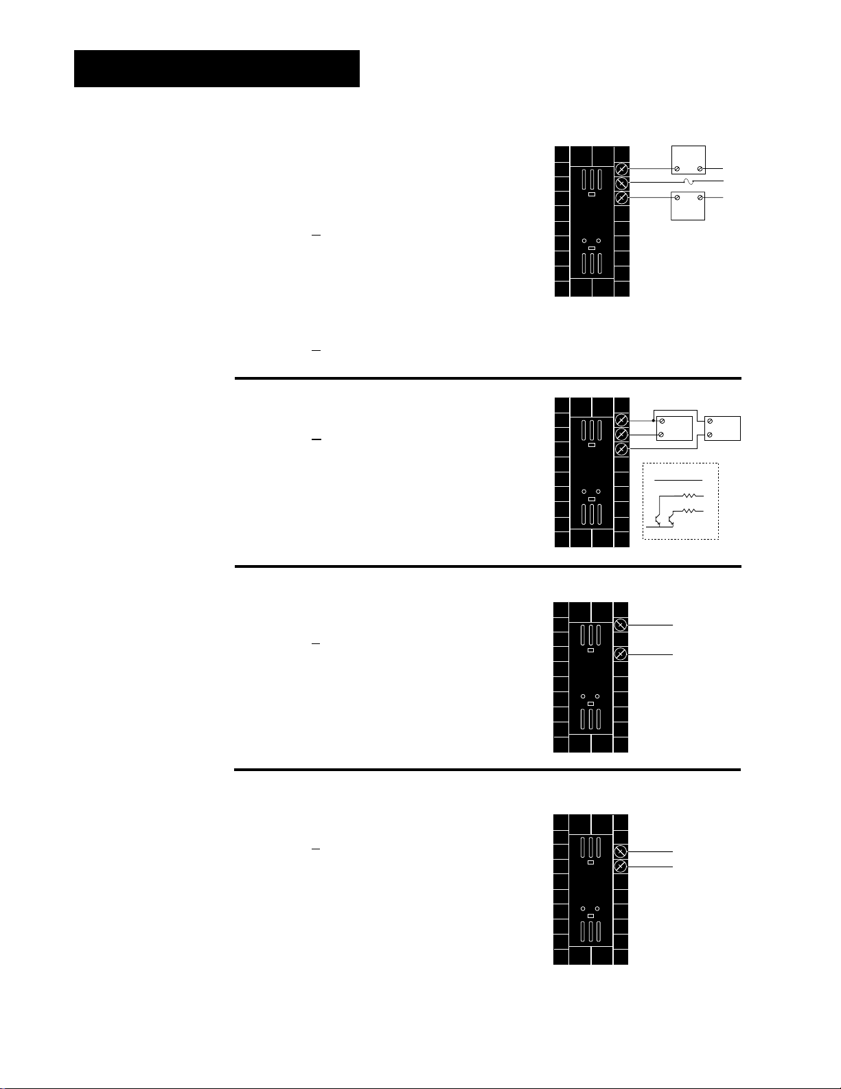
Channel A Input Wiring
NOTE:
Using a grounded
thermocouple for
both input 1 and
input 2 can cause
ground loop problems.
NOTE:
Model number
99_ _-1 _ _ _-_ _ _ _
has no input 1 DIP
switch.
Figure 2.8a
— Thermocouple
Thermocouple only
99 _ _ - 1
_ _ _ - _ _ _ _
Universal signal conditioner
99 _ _ - 2 _ _ _ - _ _ _ _
Figure 2.8b
— RTD, 2- or 3-wire
Universal signal conditioner
99 _ _ - 2
_ _ _ - _ _ _ _
Dip Switch Setting
Jumper 9 to 10
for 2-wire RTD
J, K, T, N, C, E, Pt2, D
Dip Switch Setting
R, S, B
Dip Switch Setting
ç
CAUTION:
An external resistor
is required for
0-20mA and 4-20mA
process wiring to
prevent a high inrush current which
could burn out the
controller’s 7-ohm
resistor. See page
2.4. for recommendations.
Figure 2.8c
— 0-5VÎÎ, 1-5VÎÎor 0-10VÎÎ(dc) Process
Universal signal conditioner
99 _ _ - 2 _ _ _ - _ _ _ _
Input impedance: 10KΩ
Figure 2.8d
— 0-20mA or 4-20mA Process
Universal signal conditioner
99 _ _ - 2 _ _ _ - _ _ _ _
Input impedance: 7Ω
Dip Switch Setting
Dip Switch Setting
mA
-
8
10
+
2.8 WATLOW Series 998 User’s Manual
Installation and Wiring, Chapter 2

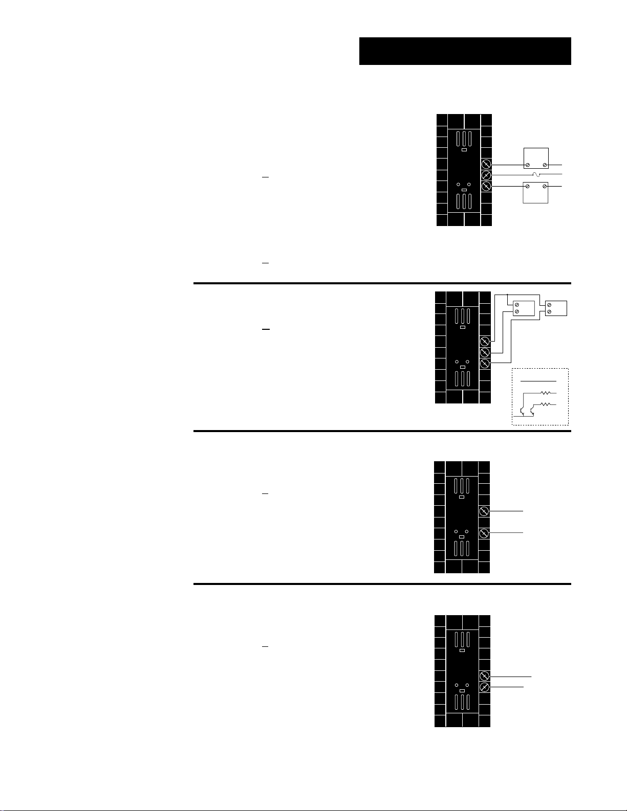
Channel B Input Wiring
19
20
+
-
19
20
18
S2
S1
19
20
18S2S1
S3
20
18
-
+
mA
20
19-+
V
DC
O
N
↑
123
O
N
↑
123
O
N
↑
123
O
N
↑
123
O
N
↑
123
NOTE:
Using a grounded
thermocouple for
both input 1 and
input 2 can cause
ground loop problems.
NOTE:
Model number
99_ _-_ 1 _ _-_ _ _ _
has no In1 DIP
switch.
Figure 2.9a — Thermocouple
Thermocouple only
99 _ _ - _ 1 _ _ - _ _ _ _
J, K, T, N, C, E, Pt2, D
Universal signal conditioner
Dip Switch Setting
99 _ _ - _ 2 _ _ - _ _ _ _
R, S, B
Dip Switch Setting
Figure 2.9b
— RTD, 2- or 3-wire
99 _ _ - _ 2 _ _ - _ _ _ _
Dip Switch Setting
Jumper
19 to 20
for 2-wire
RTD
ç
CAUTION:
An external resistor
is required for
0-20mA and 4-20mA
process wiring to
prevent a high inrush current which
could burn out the
controller’s 7-ohm
resistor. See page
2.4. for recommendations.
Figure 2.9c
99 _ _ - _ 2
— 0-5VÎÎ, 1-5VÎÎ, 0-10VÎÎ(dc) Process
_ _ - _ _ _ _
Input impedance: 10KΩ
Dip Switch Setting
Figure 2.9d — 0-20mA or 4-20mA Process
99 _ _ - _ 2 _ _ - _ _ _ _
Input impedance: 7Ω
Dip Switch Setting
Installation and Wiring, Chapter 2
WATLOW Series 998 User’s Manual 2.9
Channel A Output Wiring
14
-
+
12
14
-
+
13
Figure 2.10a — AC Outputs
• Dual Electromechanical Relays without
Contact Suppression
Dual Form A, 2 Amps
Off-state impedance: 31MΩ
99 _ _ - _ _ E _ - _ _ _ _
• Dual Solid-state Relay without
Contact Suppression
Dual Form A, 0.5 Amps
Off-state impedance: 31MΩ
99 _ _ - _ _ K
Figure 2.10b
_ - _ _ _ _
— Dual Switched DC
99 _ _ - _ _ C _ - _ _ _ _
12
NO
13
COM
14
NO
12
+
-
13
14
23.5 to 30.6VÎ (dc)
+ VÎ
Internal Circuitry
External
External
External
Load 1A
Load
Fuse
Load
1500
1500
1A
L2
L1
L2
2A
+
External
-
Load 2A
12
Ω
13
Ω
14
Figure 2.10c
— 0-20mA and 4-20mA Process
Load impedance: 800Ω max.
99 _ _ - _ _ F
Figure 2.10d
_ - _ _ _ _
— 0-5VÎÎ, 1-5VÎÎand 0-10VÎÎ(dc) Process
Load impedance: 500Ω min.
99 _ _ - _ _ F
_ - _ _ _ _
2.10 WATLOW Series 998 User’s Manual
Installation and Wiring, Chapter 2
Channel B Output Wiring
15
+
-
17
16
+
-
17
External
Load
COM
L1
L2
Fuse
NO
15
16
17
NO
External
Load
L2
1B
2B
Figure 2.11a — AC Outputs
• Dual Electromechanical Relay without
Contact Suppression
Dual Form A, 2 Amps
Off-state impedance: 31MΩ
99 _ _ - _ _ _ E - _ _ _ _
• Dual Solid-state Relay without
Contact Suppression
0.5 Amps
Off-state impedance: 31MΩ
99 _ _ - _ _ _ K
Figure 2.11b
99 _ _ - _ _ _ C
Figure 2.11c
- _ _ _ _
— Dual Switched DC
- _ _ _ _
— 0-20mA and 4-20mA Process
Load impedance: 800Ω max.
99 _ _ - _ _ _ F
- _ _ _ _
15
16
17
+
Load
1b
-
23.5 to 30.6VÎ (dc)
+ VÎ
Internal Circuitry
1500
1500
+
Load
2b
-
15
Ω
16
Ω
17
Installation and Wiring, Chapter 2
Figure 2.11d
— 0-5VÎÎ, 1-5VÎÎand 0-10VÎÎ(dc) Process
Load impedance: 500Ω min.
99 _ _ - _ _ _ F
- _ _ _ _
WATLOW Series 998 User’s Manual 2.11
Output 3 Wiring
External
Load
COM
L1
L2
Fuse
NO Form A
1
2
NC Form B
or
1
2
External
Load
-
+ VÎ
Internal Circuitry
1
2
790Ω
19 to 32VÎ (dc)
+
1
2
+
-
1
2
+
-
+V
-V
Transmitter
4-20mA out
Input
1 or 2
+
-
Figure 2.12a — AC Outputs
• Solid-state Relay with
Contact Suppression
0.5 Amps
Off-state impedance: 20KΩ min.
99 _ _ - _ _ _ _ - B
• Electromechanical Relay without
Contact Suppression
Form A or B, 5 Amps
Off-state impedance: 31MΩ
99 _ _ - _ _ _ _ - J _ _ _
Figure 2.12b
Minimum load resistance: 500Ω
99 _ _ - _ _ _ _ - C
_ _ _
Form A or B
Alarm Jumper Settings
(Top View)
— Switched DC
_ _ _
• Solid-state Relay without
Contact Suppression
0.5 Amps
Off-state impedance: 31MΩ
99 _ _ - _ _ _ _ - K _ _ _
Form B
Form A
Figure 2.12c
0-20mA, 4-20mA
Load impedance: 600Ω max.
99 _ _ - _ _ _ _ - M _ _ _
0-5VÎÎ, 1-5VÎÎor 0-10VÎÎ(dc)
NOTE:
Input-to-output isolation is defeated
when the external
transmitter power
supply is used to
power a transmitter
connected to input
1 or input 2.
Load impedance: 500Ω min.
99 _ _ - _ _ _ _ - N
Figure 2.12d — External Transmitter Power Supply
99 _ _ - _ _ _ _ - T _ _ _
See Chapter 1 for DIP switch location and set-
tings.
2.12 WATLOW Series 998 User’s Manual
— Process Retransmit
_ _ _
Installation and Wiring, Chapter 2
Output 4 Wiring
External
Load
COM
L1
L2
Fuse
NO
5
6
NC
(7 for D & E outputs only)
7
5
External
Load
6
+
+ VÎ
Internal Circuitry
5
6
7
790
19 to 32VÎ (dc)
7
-
COM
Ω
5
6
+
-
+V
-V
Transmitter
4-20mA out
Input
1 or 2
+
-
Figure 2.13a
— AC Outputs
• Solid-state Relay with
Contact Suppression
0.5 Amps
Off-state impedance: 20KΩ min.
99 _ _ - _ _ _ _ - _ B
_ _
• Solid-state Relay without
Contact Suppression
0.5 Amps
Off-state impedance: 31MΩ
99 _ _ - _ _ _ _ - _ K
_ _
• Electromechanical Relay with
Contact Suppression
(On NO and COM contacts only)
Form C, 5 Amps
Off-state impedance: 20KΩ min.
99 _ _ - _ _ _ _ - _ D _ _
• Electromechanical Relay without
Contact Suppression
Form C, 5 Amps
Off-state impedance: 31MΩ
99 _ _ - _ _ _ _ - _ E
_ _
NOTE:
Input-to-output isolation is defeated
when the external
transmitter power
supply is used to
power a transmitter
connected to input
1 or input 2.
Installation and Wiring, Chapter 2
Figure 2.13b
— Switched DC, Open Collector
Minimum load resistance: 500Ω
99 _ _ - _ _ _ _ - _ C _ _
Figure 2.13c
— External Transmitter Power Supply
99 _ _ - _ _ _ _ - _ T _ _
See Chapter 1 for DIP switch location and settings.
For data communications wiring refer to How to Use
Data Communications with the Watlow Series 988 Family Controls.
WATLOW Series 998 User’s Manual 2.13

Notes
2.14 WATLOW Series 998 User’s Manual
Installation and Wiring, Chapter 2
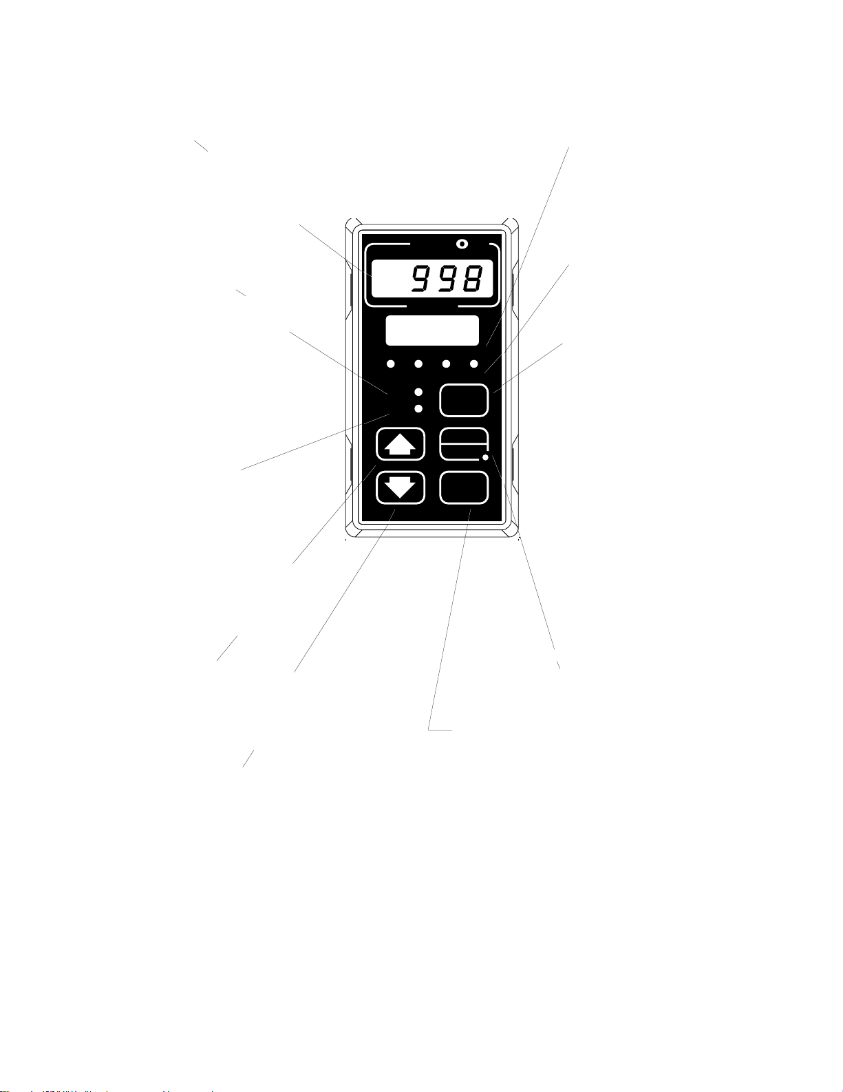
Chapter 3 Keys and Displays
Upper Display
Indicates either actual process
value for channel A or channel
B, the operating prompt values,
or error codes. When powering
up, the display will be blank for
3 seconds. Red or green, 0.4”
(10mm) high, seven-segment,
four-digit LED display.
CH A Indicator Light
When lit, if the CH B light is not
on, the channel A process value
is shown in the upper display
and the channel A set point
value is shown in the lower display. When both CH A and CH
B lights are on, the upper display shows the channel A
1A 2A 1B 2B
CH A
CH B
process value and the lower displays shows the channel B
process value.
CH B Indicator Light
When lit, if the CH A light is not
on, the channel B process value
is shown in the upper display
SERIES 998
and the channel B set point
value is shown in the lower display. When both CH A and CH
B lights are on, the upper display shows the channel A
process value and the lower display shows the channel B
process value.
Up-arrow Key >
Increases the value of the displayed prompt. A
light touch increases the value by one. Holding the
key down increases the value at a rapid rate. New
data does not take effect for five seconds or until
the Mode µ or Display ∂ key is pressed.
Down-arrow Key <
Decreases the value of the displayed prompt. A
light touch decreases the value by one. Holding the
key down decreases the displayed value at a rapid
rate. New data does not take effect for five seconds
or until the Mode µ or Display ∂ key is
pressed.
Up-arrow + Down-arrow Keys
Press simultaneously for three seconds to enter
the Setup Menu. Continue to press both keys for
another three seconds to enter the Factory Menu.
A
TL
W
PROCESS
DISPLAY
Lower Display
Indicates the channel A or
channel B set point, or channel
B process value, menu
prompts, or alarm codes. Red
or green, 0.3” (8mm) high,
W
seven-segment, four-digit LED
display.
1A, 2A, 1B, 2B Indicator
Lights
These lights indicate when output 1A, 2A, 1B or 2B is active.
Display Key ∂
The Display key is used to
select which channel A and/or
B parameter to displayed. On
initial power-up the upper display shows the channel A
AUTO
MAN
MODE
process value and the lower
display shows the channel A set
point value and the CH A light
is on. One press of the Display
key lights CH B and the upper
display shows the channel B
process value and the lower
display shows the channel B
set point value. A second press
of the key lights both CH A and
CH B, and the upper display
shows the channel A process
value and the lower display
shows the channel B process
value. See the next page for
more information on the Display Loop.
Auto/Man Key å
Used to switch from auto to manual control or vice
versa. Also used to reset alarms.
Mode Key µ
Steps the control through the menus. New data is
entered once the Mode key is pressed.
Mode+Up-arrow Key µ + >
To move backwards through the menus, hold
down the Mode key, then press the Up-arrow key
to scroll. The Mode key must be pressed first and
held before the Up-arrow key will begin scrolling.
Scrolling is disabled once the keys are released or
you reach the top of the menu.
Keys and Displays, Chapter 3
Figure 3.1 Series 998 Keys and
Displays.
WATLOW Series 998 User’s Manual 3.1

Display Loop
NOTE:
Lower display alternately flashes
[`rP`] and lower
display value when
ramping is in
process.
Display Key and Loop
On power up, the Series 998 displays the channel A set point value in the
lower display and the channel A process value in the upper display and
the CH A (channel A) indicator light is on. Press the Display key once to
view the channel B set point and process values (CH B will be lit). Press
the Display key once again and channel A process value is displayed in
the upper display and channel B process value is displayed in the lower
display. At this point, both CH A and CH B will be lit. Press the Display
key again to display units.
Any point in any menu, if no key is pressed for one minute the display
returns to displaying the channel A process and set point.
Figure 3.2 The Display Loop.
Display Loop
Channel A
Process
[`75]
[100]
Channel A
Set Point
∂
Channel B
Process
[`80]
[125]
Channel B
Set Point
∂
Channel A
Process
[`75]
[`80]
Channel B
Process
Display Loop Parameters
Channel A Process and Set Point: The channel A process value is shown
in the upper display. The set point is shown in the lower display, it sets
the operating set point for the channel A control outputs. If channel A is
in manual mode the set point is in percent output.
Range: [`rL1] to [`rH1] in auto mode
[-100] % to [`100] % in manual mode (heat/cool)
[```0] % to [`100] % in manual mode (heat only)
[-100] % to [```0] % in manual mode (cool only)
Default: depends on input 1 range and type
Channel B Process and Set Point: The channel B process value is
shown in the upper display. The set point is shown in the lower display, it
sets the operating set point for the channel B control outputs. If channel
B is in manual mode the set point is in percent output.
Range: [`rL2] to [`rH2] in auto mode
[-100] % to [`100] % in manual mode (heat/cool)
[```0] % to [`100] % in manual mode (heat only)
[-100] % to [```0] % in manual mode (cool only)
Default: depends on input 2 range and type
Process A and Process B: The channel A process value is displayed in
the upper display with channel B process value displayed in the lower
display.
Range: depends on input types
Default: none
Units: Shows the units associated with the temperature value. This parameter shows what the [`C-F] (Global Menu) is set to.
Range: [``°F] or [``°C]
Default: none
Hidden if: input 1 and input 2 are process inputs
∂
∂
[```]
[`°F]
Process
Units
3.2 WATLOW Series 998 User’s Manual
Keys and Displays, Chapter 3
TL
W
W
A
PROCESS
1A 2A 1B 2B
CH A
CH B
DISPLAY
SERIES 998
MODE
AUTO
MAN
TL
W
W
A
PROCESS
DISPLAY
MODE
1A 2A 1B 2B
CH A
CH B
SERIES 998
AUTO
MAN
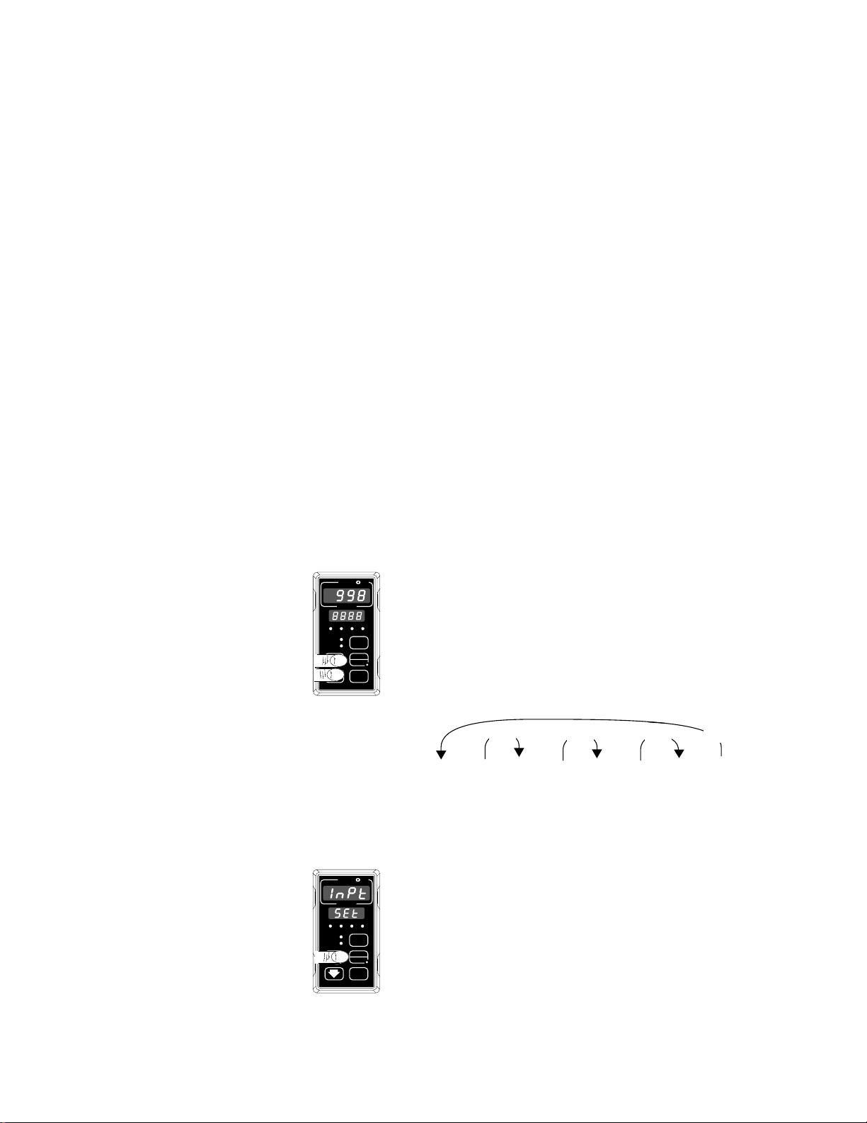
Chapter 4 The Setup Menus
Navigating the Setup Menus
To reach the Setup Menus, begin in the Display Loop and press both the
Up-arrow > and Down-arrow < keys for three seconds. The Setup
Menu prompt [`SEt] will appear in the lower display, and the Input Menu
prompt [InPt] will appear in the upper display. The four Setup Menus
are: Input [InPt]; Output [OtPt]; Global [GLbL]; and Communications
[COM]. Use the Up-arrow > or Down-arrow < key to select a menu
and the Mode key µ to step through a menu. The Communications
NOTE:
Press the Display
key ∂ to return to
the Display Loop
from any point in
any menu.
Menu appears only on units equipped with the data communications
option (99__-____-_R__ or 99__-____-_S__).
You will not see every prompt in any of these menus. The unit’s configuration and model number determine which prompts appear. After stepping
through each menu, the Series 998 returns to the Setup Menu prompt.
Use the Up-arrow or Down-arrow key to select the next menu, or use the
Mode key to advance through the same menu again. To move backwards
through the menu hold the Mode key down and press the Up-arrow key.
Use the Up-arrow or Down-arrow key to change the prompt setting.
Refer to the Appendix for model number options. For additional information about communications and the communications prompts, refer to the
supplemental manual Data Communications with the Watlow Series 988
Family of Controllers.
❶ Begin in the Display Loop, and press the Up-arrow
> and Down-arrow < keys simultaneously to
reach the Setup menus.
NOTE:
The lockout DIP
switch hides the
>>
>
>
Setup menus. See
Chapter 1.
[Inpt]
[`SEt]
[Otpt]
[`SEt]
[GLbl]
[`SEt]
[COM]
[`SEt]
Input Output Global Communications
Menu Menu Menu Menu
p. 4.2 p. 4.16 p. 4.32 p. 4.38
❷ Press the Up-arrow key > to select one of the
Setup menus.
Figure 4.1 Navigating the
Setup menus.
Setup Menus, Chapter 4
WATLOW Series 998 User’s Manual 4.1
Setup-Input
TLTL
W
W
A
PROCESS
DISPLAY
MODE
1A 2A 1B 2B
CH A
CH B
SERIES 998
AUTO
MAN
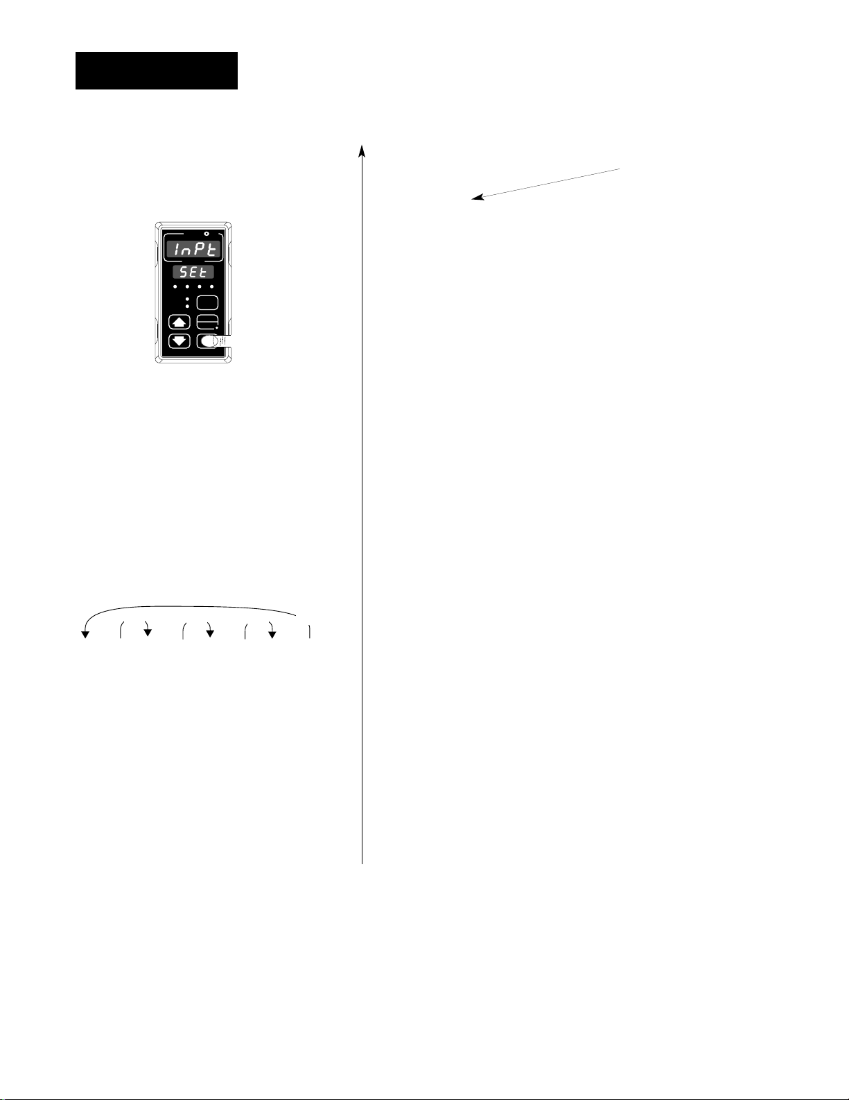
Reaching the Input Menu
❸ Select the Input Menu, then
press the Mode key µ to step
through the prompts.
>>
>
[```)]
[DEC1]
❹ Press the Up-arrow key > or
the Down-arrow key < to select
one of the prompt values.
[``)0]
[DEC1]
[`)00]
[DEC1]
[)000]
[DEC1]
>
→ [InPt] Input Menu
[`SEt] Setup Menus
µ
?
↓
[`In1] Input 1 (page 4.5)
µ
↓ ?
[dEC1] *Decimal 1
µ
↓ ?
[`rL1] Range Low 1
µ
↓ ?
[`rH1] Range High 1
µ
↓ ?
[CAL1] Calibration Offset 1
µ
↓ ?
[rtd1] *RTD Calibration Curve 1
µ
↓ ?
[Ftr1] Input 1 Software Filter
µ
↓ ?
[`In2] *Input 2 (page 4.10)
µ
↓ ?
[deC2] *Decimal 2
µ
↓ ?
[`rL2] *Range Low 2
µ
↓ ?
[`rH2] *Range High 2
µ
↓ ?
[CAL2] *Calibration Offset 2
µ
↓ ?
[rtd2] *RTD Calibration Curve 2
µ
↓ ?
[Ftr2] *Input 2 Software Filter
µ
↓ ?
[Lin2] *Input 2 Linearization
µ
↓ ?
←µ [`Alt] *Altitude
Enter your settings,
from the controller’s
upper display.
Figure 4.2 The Input Menu.
4.2 WATLOW Series 998 User’s Manual
*Prompts may not appear, depending
on controller configuration.
Setup Menus, Chapter 4
Loading...