


SF-120, SF-170, SF-250, SF-400 Bearing Mounted, Flange Mounted, SFC-120, SFC-170, SFC-250, SFC-400 Bearing Mounted, Flange Mounted
P-200 819-0481
Installation Instructions
Contents
Mounting Examples and Options . . . . . . . . . . . . . . . . .3
Installation Instructions
SF-120, SF-170, SF-250, SF-400 . . . . . . . . . . . . .4
SFC-120, SFC-170, SFC-250, SFC-400 . . . . . . . .7
Electrical Coil Data . . . . . . . . . . . . . . . . . . . . . . . . . .11
Burnishing and Maintenance . . . . . . . . . . . . . . . . . . .12
Illustration Drawings
SF-120, SF-170 Flange Mounted . . . . . . . . .14-19
SF-120, SF-170 Bearing Mounted . . . . . . . . .18-21
SF-250, SF-400 Flange Mounted . . . . . . . . .22-25
SF-250, SF-400 Bearing Mounted . . . . . . . . .26-29
SFC-120, SFC-170 Flange Mounted . . . . . . .30-33
SFC-120, SFC-170 Bearing Mounted . . . . . .34-37
SFC-250, SFC-400 Flange Mounted . . . . . . .38-41
SFC-250, SFC-400 Bearing Mounted . . . . . .42-45
Warranty . . . . . . . . . . . . . . . . . . . . . . . . . . .Back Cover
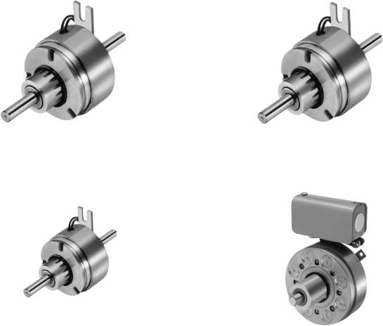
SF-120
SF-250
Follow the installation instructions in this manual carefully to ensure safe, reliable operation. All stated or implied manufacturer warranties are voided if this product is not installed in accordance with these instructions.
 Failure to follow these instructions may result in product damage, equipment damage, and serious or fatal injury to personnel.
SF-170
SF-400
2 Warner Electric • 800-825-9050 |
P-200 • 819-0481 |
Mounting Examples and Options
Warner Electric clutches are simple to install. They consist of components which must be assembled on the shaft and properly attached to the machine frame.
Various customer furnished drive components must be assembled with the clutch. Pulleys, sprockets and bearings/pillow blocks for shafting may be essential elements of a complete drive system. Squareness and concentricity tolerances are specified where critical to proper clutch/brake functioning.
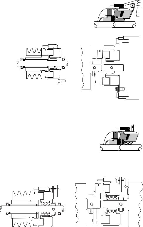
The illustrations show SF, and SFC Flange Mounted and Bearing Mounted units mounted with customer supplied bearing mounted pulley. In each illustration the drive pin for a normal duty clutch is shown. In this manner the pulley will support the armature.
SF Clutches and SFC Clutch Couplings
Flange Mounting
Concentricity tolerances, held by customer, are critical. Pilot surface required on machine member. Eliminates bearings. Good design for high speed applications.
|
|
|
|
|
|
|
|
|
|
|
|
|
|
|
|
|
|
|
|
|
|
|
|
|
|
|
|
|
|
|
|
|
|
|
|
|
|
|
|
|
|
|
|
|
|
|
|
|
|
|
|
|
|
|
|
|
|
|
|
|
|
|
|
|
|
|
|
|
|
|
|
|
|
|
|
|
|
|
|
|
|
|
|
|
|
|
|
|
|
|
|
|
|
|
|
|
|
|
|
|
|
|
|
|
|
|
|
|
|
|
|
|
|
|
|
|
|
|
|
|
|
|
|
|
|
|
|
|
|
|
|
|
|
|
|
|
|
|
|
|
|
|
|
|
|
|
|
|
|
|
|
|
|
|
|
|
|
|
|
|
|
|
|
|
|
|
|
|
|
|
|
|
|
|
|
|
|
|
|
|
|
|
|
|
|
|
|
|
|
|
|
|
|
|
|
|
|
|
|
|
|
|
|
|
|
|
|
|
|
|
|
|
|
|
|
|
|
|
|
|
|
|
|
|
|
|
|
|
|
|
|
|
|
|
|
|
|
|
|
|
|
|
|
|
|
|
|
|
|
|
|
|
|
|
|
|
|
|
|
|
|
|
|
|
|
|
|
|
|
|
|
|
|
|
|
|
|
|
|
|
|
|
|
|
|
|
|
|
|
|
|
|
|
|
|
|
|
|
|
|
|
|
|
|
|
|
|
|
|
|
|
|
|
|
|
|
|
|
|
|
|
|
|
|
|
|
|
|
|
|
|
|
|
|
|
|
|
|
|
|
|
|
|
|
|
|
|
|
|
|
|
|
|
|
|
|
|
|
|
|
|
|
|
|
|
|
|
|
|
|
|
|
|
|
|
|
|
|
|
|
|
|
|
|
|
|
|
|
|
|
|
|
|
|
|
|
|
|
|
|
|
|
|
|
|
|
|
|
|
|
|
|
|
|
|
|
|
|
|
|
|
|
|
|
|
|
|
|
|
|
|
|
|
|
|
|
|
|
|
|
|
|
|
|
|
|
|
|
|
|
|
|
|
|
|
|
|
|
|
|
|
|
|
|
|
|
|
|
|
|
|
|
|
|
|
|
|
|
|
|
|
|
|
|
|
|
|
|
|
|
|
|
|
|
|
|
|
|
|
|
|
|
|
|
|
|
|
|
|
|
|
|
|
|
|
|
|
|
|
|
|
|
|
|
|
|
|
|
|
|
|
|
|
|
|
|
|
|
|
|
|
|
|
|
|
|
|
|
|
|
|
|
|
|
|
|
|
|
|
|
|
|
|
|
|
|
|
|
|
|
|
|
|
|
|
|
|
|
|
|
|
|
|
|
|
|
|
|
|
|
|
|
|
|
|
|
|
|
|
|
|
|
|
|
|
|
|
|
|
|
|
|
|
|
|
|
|
|
|
|
|
|
|
|
|
|
|
|
|
|
|
|
|
|
|
|
|
|
|
|
|
|
|
|
|
|
|
|
|
|
|
|
|
|
|
|
|
|
|
|
|
|
|
|
|
|
|
|
|
|
|
|
|
|
|
|
|
|
|
|
|
|
|
|
|
|
|
|
|
|
|
|
|
|
|
|
|
|
|
|
|
|
|
|
|
|
|
|
|
|
|
|
|
|
|
|
|
|
|
|
|
|
|
|
|
|
|
|
|
|
|
|
|
|
|
|
|
|
|
|
|
|
|
|
|
|
|
|
|
|
|
|
|
|
|
|
|
|
|
|
|
|
|
|
|
|
|
|
|
|
|
|
|
|
|
|
|
|
|
|
|
|
|
|
|
|
|
|
|
|
|
|
|
|
|
|
|
|
|
|
|
|
|
|
|
|
|
|
|
|
|
|
|
|
|
|
|
|
|
|
|
|
|
|
|
|
|
|
|
|
|
|
|
SF Clutch |
|
|
|
|
|
|
|
SFC Clutch Coupling |
|
|
|
|
|||||||||||||||||||||||||||||||||||
|
Typical Installation |
|
|
|
|
|
|
|
Typical Installation |
|
|
|
|
|||||||||||||||||||||||||||||||||||
|
|
|
|
|
|
|
|
|
|
|
|
|
|
|
|
|
|
|
|
|
|
|
|
|
|
|
|
|
|
|
|
|
|
|
|
|
|
|
|
|
|
|
|
|
|
|
|
|
Bearing Mounting
Bearing supports field and holds close tolerances required between rotor and field. Easy to install and priced about the same as the flange mounted design.
|
|
|
|
|
|
|
|
|
|
|
|
|
|
|
|
|
|
|
|
|
|
|
|
|
|
|
|
|
|
|
|
|
|
|
|
|
|
|
|
|
|
|
|
|
|
|
|
|
|
|
|
|
|
|
|
|
|
|
|
|
|
|
|
|
|
|
|
|
|
|
|
|
|
|
|
|
|
|
|
|
|
|
|
|
|
|
|
|
|
|
|
|
|
|
|
|
|
|
|
|
|
|
|
|
|
|
|
|
|
|
|
|
|
|
|
|
|
|
|
|
|
|
|
|
|
|
|
|
|
|
|
|
|
|
|
|
|
|
|
|
|
|
|
|
|
|
|
|
|
|
|
|
|
|
|
|
|
|
|
|
|
|
|
|
|
|
|
|
|
|
|
|
|
|
|
|
|
|
|
|
|
|
|
|
|
|
|
|
|
|
|
|
|
|
|
|
|
|
|
|
|
|
|
|
|
|
|
|
|
|
|
|
|
|
|
|
|
|
|
|
|
|
|
|
|
|
|
|
|
|
|
|
|
|
|
|
|
|
|
|
|
|
|
|
|
|
|
|
|
|
|
|
|
|
|
|
|
|
|
|
|
|
|
|
|
|
|
|
|
|
|
|
|
|
|
|
|
|
|
|
|
|
|
|
|
|
|
|
|
|
|
|
|
|
|
|
|
|
|
|
|
|
|
|
|
|
|
|
|
|
|
|
|
|
|
|
|
|
|
|
|
|
|
|
|
|
|
|
|
|
|
|
|
|
|
|
|
|
|
|
|
|
|
|
|
|
|
|
|
|
|
|
|
|
|
|
|
|
|
SF Clutch |
|
SFC Clutch Coupling |
|||||||||||||||||||||||||||||||||
Typical Installation |
|
|
|
Typical Installation |
|||||||||||||||||||||||||||||||
Warner Electric • 800-825-9050 |
P-200 • 819-0481 3 |
Clutch SF-120, SF-170, SF-250, SF-400
Installation Instructions
A.Installing the Conduit Box
To install the conduit box on the size 400 units, refer to the instructions supplied with conduit box.
B.Mounting the Field-and-Rotor Assembly
Flange-Mounted Units
The fields and rotors are shipped separately for flange-mounted units. On some applications it may be necessary to mount the rotor first, and then bring the field into position. In other instances the field may be mounted first, and then the rotor (mounted on a shaft) will be inserted into place.
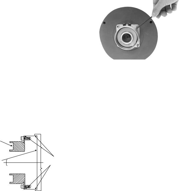
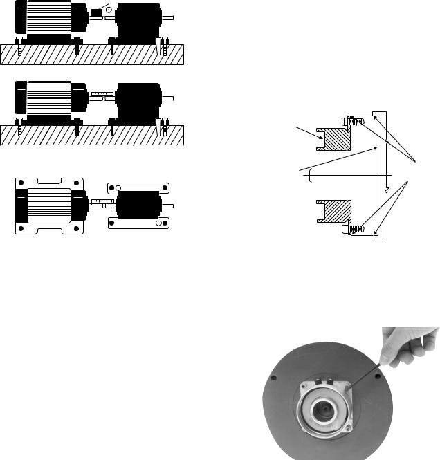
1.Care must be taken in selecting the location for mounting the field assembly. Pilot diameters are machined on the field mounting flange to aid in holding the field in the proper position.
2.An appropriate pilot diameter must be provided on the mounting surface as well. (Figure 1)
Field
Mounting |
|
|
Pilot |
Surface |
|
|
Diameters |
|
|
|
|
|
|
|
|
Figure 1
3.The field assembly is then fastened in place with capscrews and lockwashers. (Figure 2)
4.After the unit is in place, the mounting face and pilot must be square and concentric with the shaft in accordance with the tolerances listed on the drawings.
5.Insert a key into the shaft keyway.
6.Slide the rotor assembly onto the shaft over the key.
Figure 2
7.Secure the assembly in this position by alternately tightening the two setscrews.
8.Position the field and rotor in accordance with the overall axial dimension shown on the illustration drawings for correct size unit. Holding this dimension will assure the proper clearance between the field and rotor.
Bearing-Mounted Units
In bearing-mounted units, the field and rotor are shipped as an assembly. Either this assembly or the armature and hub assembly can be mounted on the shaft first, depending on the characteristics on each application.
1.Insert the key into the shaft keyway.
2.Slide the rotor assembly over the key and on to the shaft.
3.Secure the field-and-rotor assembly in place by alternately tightening the two set screws.
Note: The field-and-rotor assemblies for 120 units and 250 units, 1/2 inch bore, are held in place by set screws inserted into a set collar on the end of the rotor hub extension. Secure these assemblies in place by alternately tightening the screws.
4.A tab or torque arm on the field is used to prevent rotation of the field caused by normal bearing drag. Insert either a pin in the U-slot or a fork around the torque arm to prevent this rotation. Under no circumstances, however, should the field be so tightly restrained as to preload the bearing.
4 Warner Electric • 800-825-9050 |
P-200 • 819-0481 |
C.Assembling the Armature and Hub
The clutch units contain an extended armature hub mounted on sleeve bearings. These hubs may be adapted to a customer-supplied sheave, sprocket, or gear for transmitting power to a parallel shaft.
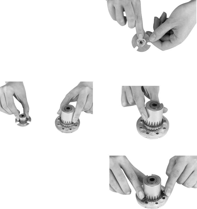
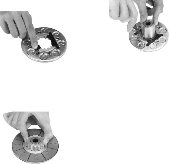
1.The antibacklash armatures are shipped assembled and ready to be installed. See Section D.
2.The standard armature and hub must be assembled before it can be installed. Assemble the armatures so that the shiny surfaces size (120 and 170) or backing plate sides size (250 and 400) are against the hub retainer ring (Figure 3).
Figure 3
3.An optional release spring may be used with the standard armatures and hubs. The release spring forces the armature back against the hub retainer ring when the magnet coil is de-energized.
Follow these instructions to assemble the armature and hub when the optional release springs are being used.
SF-170
Assemble the splined armature to the hub. The shiny side of the armature should be against the hub retainer ring.
Assemble the release spring into the groove in the hub spline. The curved portion of the spring should be against the armature (Figure 4).
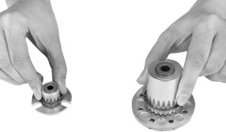
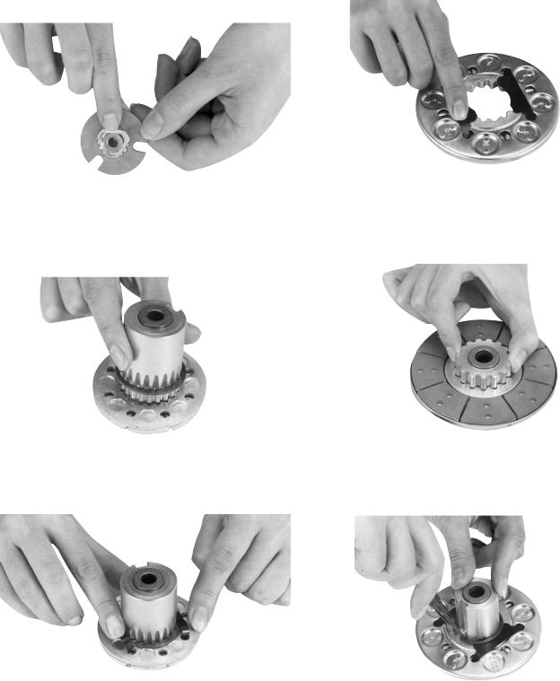
SF-250
Insert the hub, with snap ring intact, into the armature from the backing plate side. (See Figure 5)
Figure 4
Insert both release springs into the holes of the backing plate. Bow the springs as necessary to insert them into the armature. (See Figure 6)
Figure 5
Figure 6
Warner Electric • 800-825-9050 |
P-200 • 819-0481 5 |
SF-400
Insert the release springs into the backing plate holes of the armature. Bow the springs as necessary to insert them into the armature. (See Figure 7)
Figure 7
Remove the snap ring from the hub.
Insert the hub, with the setscrew end first, into the armature from the segmented side. Slide the hub into the armature until the release springs engage the snap ring groove. (See Figure 8)
Figure 8
Assemble the snap ring into the groove in the hub, clamping the release spring against the end of the spline. (See Figure 9)
Figure 9
D. Mounting the Armature Assembly
1.Slide the armature assembly onto the shaft. Position the assembly in accordance with the overall axial dimensions given on the illustration drawings.
2.The armature-hub assembly can be held in this position with retainer rings, a set collar, a shoulder on the shaft, or any combination of these. The hub may need to be repositioned as wear occurs with time.
6 Warner Electric • 800-825-9050 |
P-200 • 819-0481 |
Clutch-Coupling SFC-120, SFC-170,
SFC-250, SFC-400
Installation Instructions
A.Aligning the Shafts
In order for the clutch-coupling unit to operate properly, the mounting shafts of the motor and reducer or other hardware must be aligned with respect to each other before the unit is installed. The two shafts should be concentric with each other within .004 T.I.R., and angular alignment should be within 1/2 degree.
B.Installing the Conduit Box
To install the conduit box on the size 400 units, refer to the instructions supplied with conduit box.
C.Mounting the Field-and-Rotor Assembly Flange-Mounted Units
The fields and rotors are shipped separately for flange-mounted units. On some applications it will be necessary to mount the rotor first, and then bring the field into position. In other instances the field will be mounted first, and then the rotor (mounted on a shaft) will be inserted into place.
1.Care must be taken in selecting the location for mounting the field assembly. Pilot diameters are machined on the field mounting flange to aid in holding the field in the proper position. (Figure 1)
Field
Mounting |
|
|
Pilot |
Surface |
|
|
Diameters |
|
|
|
|
|
|
|
|
1.Use a straight-edge to check if the shafts are aligned with each other. For a more precise indication of alignment, use a dial indicator. (Figure 10)
2.Adjust the position of the motor, reducer, or other hardware as required to achieve the correct alignment.
3.To be sure the shafts stay in alignment, drill holes for tapered dowel pins through the mounting bases of the motor, reducer, or other hardware and into the mounting surfaces. This procedure will ensure that, after the clutchcoupling has been installed, the shafts can easily be placed in proper alignment again by lining up the holes and secured by inserting the dowel pins.
Figure 1
2.An appropriate pilot diameter must be provided on the mounting surface as well.
3.The field assembly is then fastened in place with capscrews and lockwashers. (Figure 2)
Figure 2
Warner Electric • 800-825-9050 |
P-200 • 819-0481 7 |
4.After the unit is in place, the mounting face and pilot diameter must be square and concentric with the shaft in accordance with the tolerances listed on the drawings.
5.Insert a key into the shaft keyway.
6.Slide the rotor assembly onto the shaft over the key.
7.Secure the assembly in this position by alternately tightening the two setscrews.
8.Position the field and rotor in accordance with the overall axial dimension shown on the illustration drawings. Holding this dimension will assure the proper clearance between the field and rotor.
Bearing-Mounted Units
In bearing-mounted units, the field and rotor are shipped as an assembly. Either this assembly or the armature and hub assembly can be mounted on the shaft first, depending on the characteristics of each application.
1.Insert the key into the shaft keyway.
2.Slide the rotor assembly over the key and on to the shaft.
3.Secure the field-and-rotor assembly in place by alternately tightening the two set screws.
Note: The field-and-rotor assemblies for 120 units and 250 units, 1/2 inch bore, are held in place by set screws inserted into a set collar on the end of the rotor hub extension. Secure the assembly in place by alternately tightening the screws.
4.A tab or torque arm on the field is used to prevent rotation of the field caused by normal bearing drag. Insert either a pin in the U-slot or a fork around the torque arm to prevent this rotation. Under no circumstances, however, should the field be so tightly restrained as to preload the bearing.
C.Assembling the Armature and Hub
1.The antibacklash armatures are shipped assembled and ready to be installed. See Section D.
2.The standard armature and hub must be assembled before it can be installed. Assemble the armatures so that the shiny surfaces size (120 and 170) or backing plate sides size (250 and 400) are against the hub retainer ring (Figure 3).
Figure 3
3.An optional release spring may be used with the standard armatures and hubs. The release spring forces the armature back against the hub retainer ring when the magnet coil is de-energized.
Follow these instructions to assemble the armature and hub when the optional release springs are being used.
8 Warner Electric • 800-825-9050 |
P-200 • 819-0481 |
SFC-170
Assemble the splined armature to the hub. The shiny side of the armature should be against the hub retainer ring.
Assemble the release spring into the groove in the hub spline. The curved portion of the spring should be against the armature (Figure 4).
Figure 4
SFC-250
Insert the hub, with snap ring intact, into the armature from the backing plate side. (See Figure 5)
Figure 5
Insert both release springs into the holes of the backing plate. Bow the springs as necessary to insert them into the armature. (See Figure 6)
SFC-400
Insert the release springs into the backing plate holes of the armature. Bow the springs as necessary to insert them into the armature. (See Figure 7)
Remove the snap ring from the hub.
Figure 7
Insert the hub, with the setscrew end first, into the armature from the segmented side. Slide the hub into the armature until the release springs engage the snap ring groove. (See Figure 8.)
Figure 8
Assemble the snap ring into the groove in the hub, clamping the release spring against the end of the spline. (See Figure 9.)
Figure 6 |
Figure 9 |
|
|
|
|
Warner Electric • 800-825-9050 |
P-200 |
• 819-0481 9 |
D. Mounting the Armature Assembly
1.SFC 250 and 400 size units.
Insert a key in the keyslot of the shaft and slide the armature assembly onto the shaft.
2.(SFC120 do not use keyway)
Position the assembly to allow a gap of about 1/64 inch between the faces of the armature and magnet. The overall axial dimension should be in accordance with the dimensions specified on the illustration drawings.
3.Secure the assembly in this position by alternately tightening the two setscrews in the hub.
4.The hub may need to be repositioned as wear occurs with time.
Electrical Coil Data
Unit Size |
|
SF/SFC 120 |
|
|
SF/SFC 170 |
|
|||
Voltage – DC |
6 |
|
24 |
|
90 |
6 |
|
24 |
90 |
Resistance @ 20°C — Ohms |
6.32 |
|
104 |
|
1386 |
6.96 |
|
111.2 |
1506 |
Current — Amperes |
.949 |
|
.230 |
|
.065 |
.861 |
|
.215 |
.060 |
Watts |
5.69 |
|
5.52 |
|
5.85 |
5.85 |
|
5.16 |
5.37 |
Coil Build-up — Milliseconds |
12 |
|
12 |
|
11 |
17 |
|
17 |
16 |
Coil Decay — Milliseconds |
8 |
|
8 |
|
7 |
8 |
|
7 |
6 |
Unit Size |
|
|
SF/SFC 250 |
|
|
SF/SFC 400 |
|
||
Voltage – DC |
6 |
|
24 |
|
90 |
6 |
|
90 |
|
|
|
|
24 |
||||||
Resistance @ 20°C — Ohms |
5 |
|
76.4 |
|
1079 |
4.88 |
|
73 |
1087 |
Current — Amperes |
1.2 |
|
.314 |
|
.084 |
1.23 |
|
.322 |
.083 |
Watts |
7.2 |
|
7.5 |
|
7.51 |
7.39 |
|
7.96 |
7.45 |
Coil Build-up — Milliseconds |
48 |
|
48 |
|
44 |
154 |
|
154 |
154 |
Coil Decay — Milliseconds |
15 |
|
15 |
|
13 |
62 |
|
60 |
55 |
Notes: Build-up time equals current to approximately 90% of steady state value and flux to 90%. Decay time equals current to approximately 10% of steady state value and flux to 10%. Approximately because current leads or lags flux by a small amount.
10 Warner Electric • 800-825-9050 |
P-200 • 819-0481 |
Burnishing and Maintenance
Burnishing
Intimate metal to metal contact is essential between the armature and the metal rings (poles) of the magnet or rotor. Warner Electric clutches and brakes leave the factory with the friction material slightly undercut to assure good initial contact.
Normally, the desired wearing-in process occurs naturally as the surfaces slip upon engagement. The time for wear-in, which is necessary to obtain the ultimate torque of the unit, will vary depending on speed, load, or cycle duty.
If maximum torque is required immediately after installation, the unit should be burnished by slipping the friction surfaces together at reduced voltage. It is recommended that the burnishings be done right on the application, if at all possible.
Burnishing at high speed will result in a smoother wear-in pattern and reduce the time for burnishing. The voltage should be set at approximately 30% or 40% of the rated value.
The unit should be cycled on and off to allow sufficient time between slip cycles to prevent overheating.
When a Warner Electric brake or clutch is properly assembled and installed, no further servicing, lubrication, or maintenance should be required throughout the life of the unit.
Maintenance
Wear Pattern: Wear grooves appear on the armature and magnet surfaces. This is a normal wear condition, and does not impair functioning of the unit. Normally, the magnet and armature, as a mating pair, will wear at the same rate. It is the usual recommendation that both components be replaced at the same time.
Remachining the face of a worn armature is not recommended. If a replacement armature is to be used with a used magnet, it is necessary to remachine the worn magnet face. In refacing a magnet: (1) machine only enough material to clean up the complete face of the magnet; (2) hold the face within .005" of parallel with the mounting plate; and (3) undercut the molded facing material .001" - .003" below the metal poles.
Heat: Excessive heat and high operating temperatures are causes of rapid wear. Units, therefore, should be ventilated as efficiently as possible, especially if the application requires fast, repetitive cycle operation.
Foreign Materials: If units are used on machinery where fine, abrasive dust, chips or grit are dispelled into the atmosphere, shielding of the brake may be necessary if maximum life is to be obtained.
Where units are used near gear boxes or transmissions requiring frequent lubrication, means should be provided to protect the friction surfaces from oil and grease to prevent serious loss of torque.
Oil and grease accidentally reaching the friction surfaces may be removed by wiping with a rag dampened with a suitable cleaner, which leaves no residue. In performing this operation, do not drench the friction material.
If the friction materials have been saturated with oil or grease, no amount of cleaning will be completely effective. Once such a unit has been placed back in service, heat will cause the oil to boil to the surface, resulting in further torque loss.
Torque Loss: If a brake or clutch slips or loses torque completely, the initial check should be the input voltage to the magnet as follows:
90-Volt Series: Connect a DC voltmeter with a range of 0-100 or more directly across the magnet terminals. With the power on and the potentiometer turned up, a normal reading is 90 volts, although 85 to 95 is satisfactory. The reading should drop as the potentiometer control is adjusted counterclockwise.
24-Volt Series: Use a DC voltmeter with a range of 0- 30 volts or more. A normal reading is approximately 2226 volts.
6-Volt Series: Use a DC voltmeter of approximately 0- 15 volt range. A normal reading is from 5.5 to 6.5 volts.
The above checks normally are sufficient. Further checks may be made as follows: a low range ammeter, when connected in series with one magnet lead, will normally indicate approximately .40 amperes for the 90 volt units, 1.0 ampere for the 24 volt, and 3.5 amperes for the 6 volt series. These readings are with the power on and the potentiometer control in the maximum position.
Warner Electric • 800-825-9050 |
P-200 • 819-0481 11 |
Ohmmeter checks should be made with the power off and the circuit open (to be certain, disconnect one lead to the magnet). Average resistance for the 90 volt series is 220 ohms; for the 24 volt, 20 ohms; and for the 6 volt series, 1.5 ohms. A very high or infinite resistance reading would indicate an open coil.
If the above checks indicate that the proper voltage and current is being supplied to the magnet, mechanical parts should be checked to assure that they are in good operating condition and properly installed.
12 Warner Electric • 800-825-9050 |
P-200 • 819-0481 |
Warner Electric • 800-825-9050 |
P-200 • 819-0481 13 |

SF-120 Clutch Flange Mounted |
|
|
|
|
|
|
For Bore sizes see |
|
|
|
|
|
|
chart below. |
|
|
|
|
|
.156 |
|
|
|
|
|
|
|
|
|
|
|
.035/.004 (Std.) |
|
|
|
|
|
|
.020/.008 (Anti.) |
|
|
|
|
|
|
When New |
|
|
Std. Arm. |
|
|
|
.072 (Std.) |
12 |
|
|
|
|
|
.072 (Anti.) |
.062 |
|
Antibacklash Arm. |
|
|
|
|
|
|
|
|
|
.020 |
|
|
|
|
|
|
|
* |
|
|
|
|
|
|
.000 |
|
|
|
|
|
|
.375 |
|
|
|
|
|
|
(Std.) |
|
|
|
|
.502 |
.031 |
.375 |
|
.109 |
|
|
(Anti.) |
|
|
||
|
|
.500 |
|
|
|
|
|
|
|
|
|
|
|
|
Armature View |
|
|
|
|
.065/.062 dia. |
|
|
1.234 |
|
Std. Arm |
|
2 holes equally |
|
|
|
|
spaced |
||
|
|
|
|
|
||
|
|
Max. Dia. |
|
|
|
|
|
|
|
Antibacklash Arm |
|
||
|
|
|
|
|
||
For Bore sizes see |
1.499/1.497 |
|
|
|
|
|
Pilot Dia. |
|
|
|
|
|
|
chart below. |
.515 |
|
|
|
|
|
|
|
|
|
.019 |
||
|
|
|
|
|
||
|
|
.511 |
|
|
|
.000 |
|
|
|
|
|
|
#4-40 |
|
|
|
|
.375 |
|
UNC-3A |
|
|
|
|
|
|
|
|
45° |
|
|
(Std.) |
.072 (Std.) |
|
|
|
|
.375 |
|
||
|
|
|
|
.072 (Anti.) |
|
|
|
|
|
|
(Anti.) |
|
|
|
|
|
|
.546 |
.187 |
|
|
|
|
|
|
||
|
|
|
|
.528 |
Max. |
|
|
|
|
|
.625 |
||
|
|
|
|
|
|
|
|
|
|
|
|
1.171 Max. |
|
|
|
* Mounting holes are within .006 of true position relative to pilot diameter. |
||||
|
|
|
|
|
|
|
.130/.123 dia. |
|
|
|
|
|
|
|
|
|
4 holes equally |
|
|
|
|
|
|
|
|
|
spaced on 1.312 |
|
|
|
|
|
|
|
|
|
dia. B.C.* |
Bore Dimensions |
|
|
|
|
|
|
|
|
|
||
|
|
|
|
|
|
|
|
|
|
|
|
|
|
|
|
|
|
|
|
|
|
|
|
|
|
|
|
Rotor |
Armature |
|
|
|
|
|
|
|
|
||
|
|
|
|
|
|
|
|
||
|
|
Field View |
|
||||||
|
|
|
Bore Dia. |
Bore Dia. |
|||||
|
|
|
|
|
|
|
|
||
|
|
|
|
|
|
|
|
|
|
|
|
|
|
|
|
|
|
.188/.187 |
.195/.190 |
|
|
|
|
|
|
|
|
.251/.250 |
.257/.252 |
|
|
|
|
|
|
|
|
.313/.312 |
— |
Customer Shall Maintain:
1.Squareness of field mounting face with shaft with
.003 T.I.R. measured at pilot diameter.
2.Concentricity of field mounting pilot diameter with rotor mounting shaft within .003 T.I.R.
Armature Shaft |
.187 – .250 |
|
|
Rotor Shaft |
.187 – .312 |
Static Torque |
5 lb. in. |
|
|
Maximum Speed |
3,600 rpm |
|
|
Standard Voltage |
D.C. 6, 24, 90 |
All dimensions are nominal unless otherwise noted.
14 Warner Electric • 800-825-9050 |
P-200 • 819-0481 |
 Loading...