


EP-170
Warner Electric EP-170, EP-250, EP-400, EP-500, EP-825 User Manual
...
Installation Instructions
P-212
819-0078
Electro-Packs
EP-170, 250, 400, 500, 825, 1000, 1525
2
Warner Electric • 800-825-9050 P-212 • 819-0078
Contents
Features . . . . . . . . . . . . . . . . . . . . . . . . . . . . . 2
Selection . . . . . . . . . . . . . . . . . . . . . . . . . . . . . 3
Installation Instructions . . . . . . . . . . . . . . . . . . 4
Replacing Worn Parts . . . . . . . . . . . . . . . . . . . 4
Burnishing and Maintenance . . . . . . . . . . . . . . 6
Electrical Data Coil Ratings . . . . . . . . . . . . . . . 8
Exploded Views and Parts List
EP-170, 250, 400 . . . . . . . . . . . . . . . . . . . . 9
EP-500 . . . . . . . . . . . . . . . . . . . . . . . . . . . 12
EP-825 . . . . . . . . . . . . . . . . . . . . . . . . . . . 14
EP-1000 . . . . . . . . . . . . . . . . . . . . . . . . . . 16
EP-1525, 1525 HT. . . . . . . . . . . . . . . . . . . 17
Warranty . . . . . . . . . . . . . . . . . . . . . . Back Page
Failure to follow these
instructions may result in product damage,
equipment damage, and serious or fatal
injury to personnel.
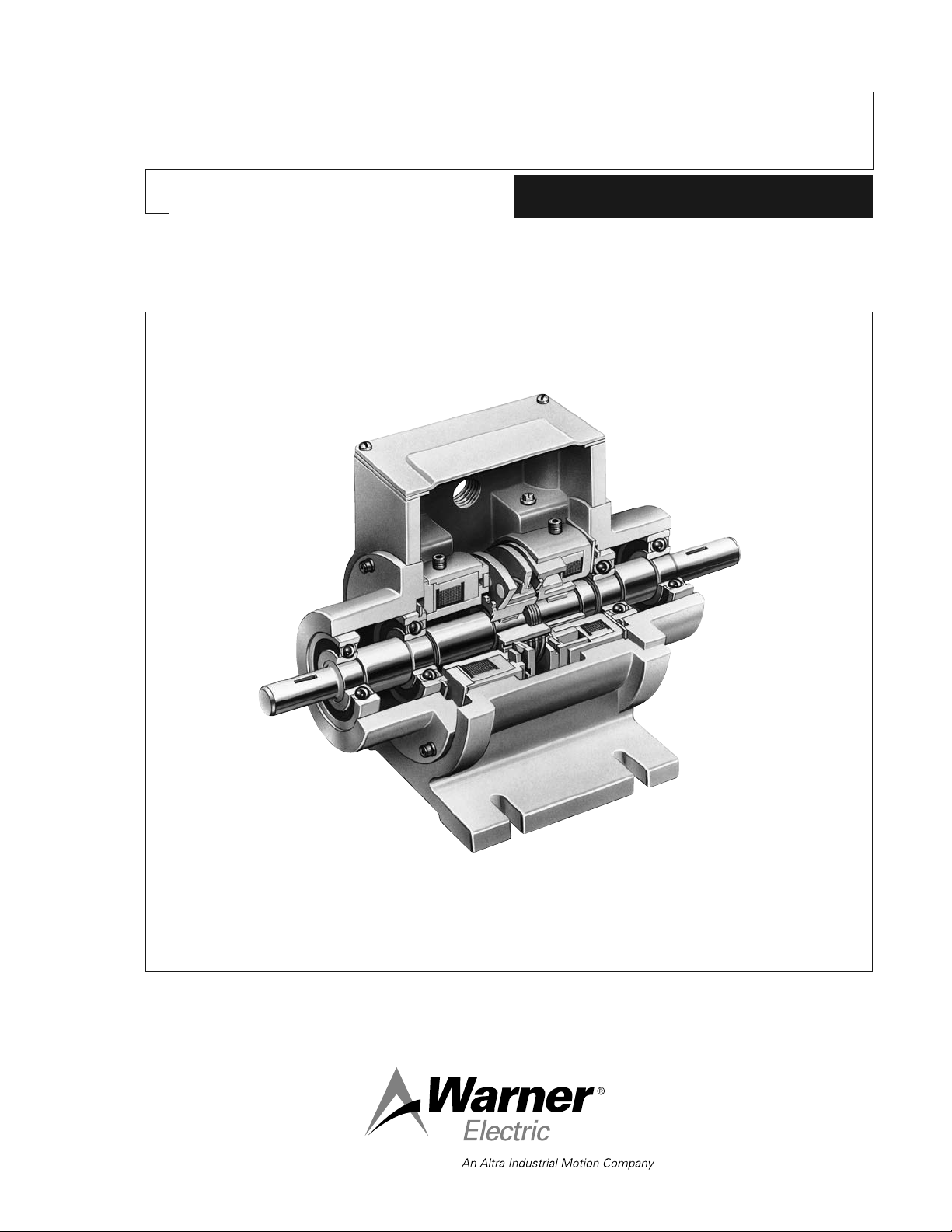
Base Mounted Clutch/Brake
Combinations in a Rugged Housing
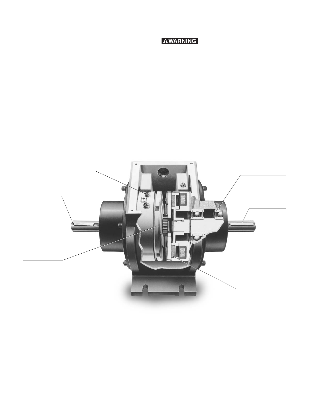
Meets electrical codes
UL Listed or CSA Certified.
Pre-packaged
Over 20 major compo-
nents have been pre-
engineered and
pre-assembled in a
typical Electro Pack.
Ready-to-go, straight
from the box.
Brake output shaft
Foot mounted
Bolt-it-down and wire-it-up. Allows for
quick replacement/reduced downtime.
Maintenance free
Never needs lubrication.
Self-adjusting for wear of
clutch-brake friction faces.
Consistent performance.
Clutch input shaft
Heavy duty bearings
Properly aligned for
maximum performance.
3
Part Numbers
Model Voltage
No. DC Part No.
EP-170 6 5633-273-002
24 5633-273-003
90 5633-273-005
EP-250 6 5130-273-031
24 5130-273-032
90 5130-273-034
EP-400 6 5131-273-009
24 5131-273-010
90 5131-273-011
EP-500 6 5230-273-003
24 5230-273-011
90 5230-273-002
EP-825 6 5231-273-003
24 5231-273-004
90 5231-273-002
EP-1000 6 5232-273-003
24 5232-273-005
90 5232-273-002
EP-1525 6 5234-273-003
90 5234-273-002
EP-1525HT 90 5234-273-012
When ordering, specify size, voltage, and
part numbers.
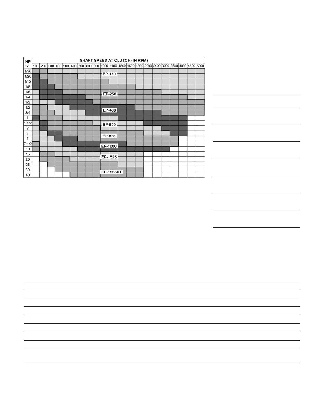
Selection Procedure
Determine the shaft speed at the Electro
Pack location. The number listed at the
intersection of horsepower and speed is
the size Electro Pack you require.
Horsepower vs. Shaft Speed
Specifications
Electro-Pack Size Horsepower @ 1800 RPM Static Torque Max. RPM Voltage DC
EP-170 1/8 15 lb. in. 10,000 6, 24 or 90
EP-250 1/2 70 lb. in. 7,500 6, 24 or 90
EP-400 1 270 lb. in. 4.500 6, 24 or 90
EP-500 2 50/40 lb. ft. 4,000 6 or 90
EP-825 7-1/2 125 lb. ft. 3,600 6 or 90
EP-1000 10 240 lb. ft. 3,000 6 or 90
EP-1525 25 700 lb. ft. 1,800 6 or 90
EP-1525HT 40 1350 lb. ft. clutch 1,800 90
700 lb. ft. brake
Clutch/Brake Selection Information
4
Warner Electric • 800-825-9050 P-212 • 819-0078
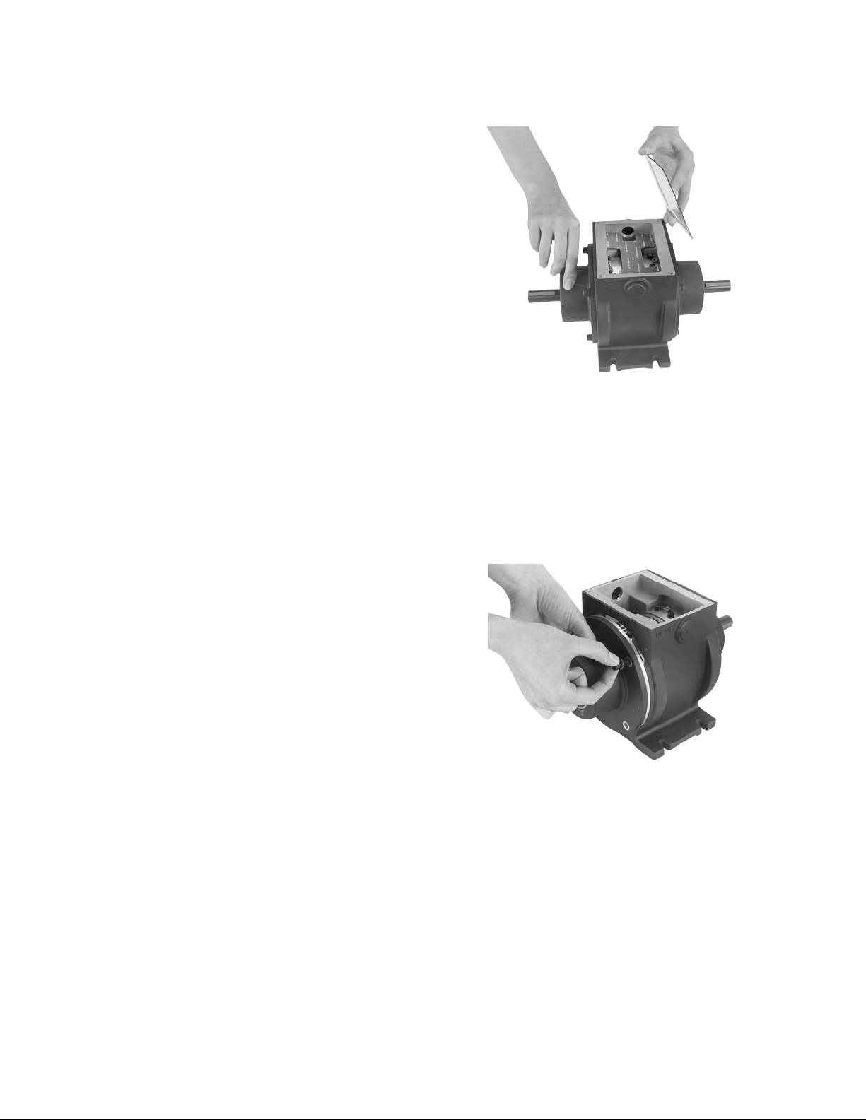
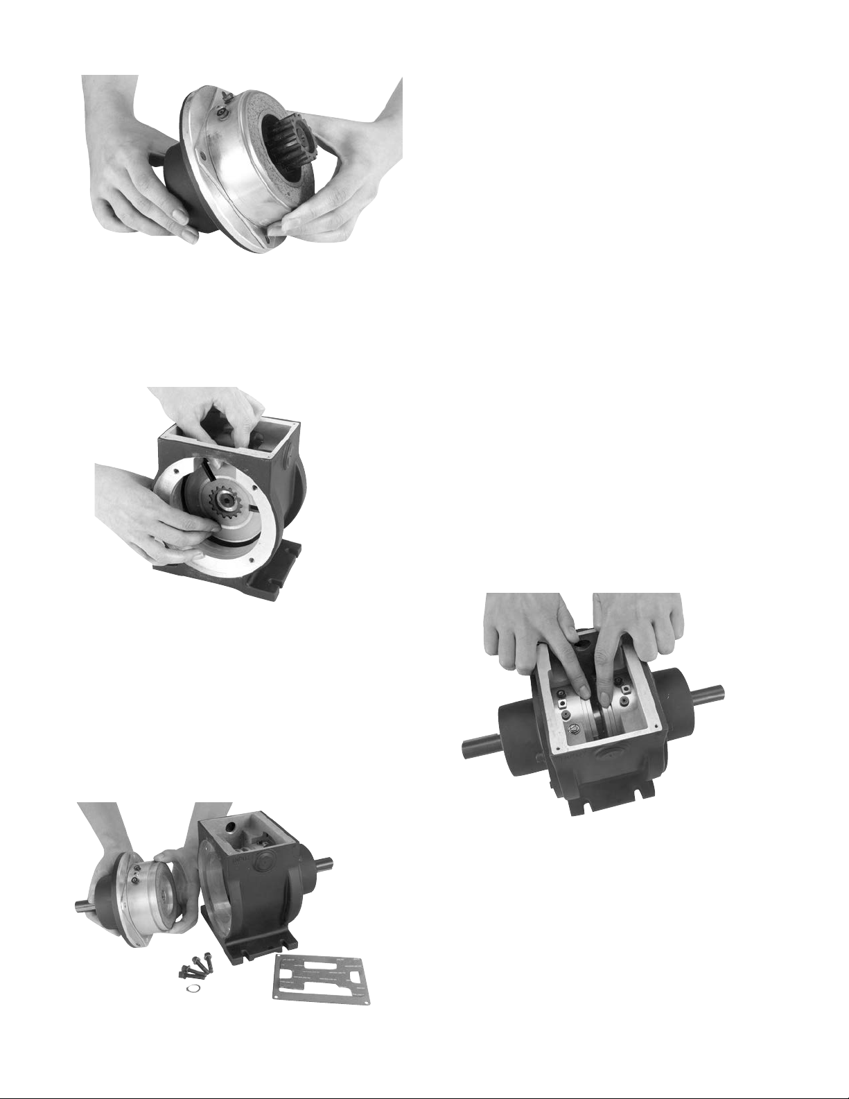
1. Remove the cover from the Electro-Pack unit.
(Figure 1)
2. Disconnect the wires from the magnet
terminals or disconnect the lead wires
(EP-170).
3. Remove the capscrews and washers from the
output end bell and remove the end bell.
(Figure 2)
4. Remove and discard the worn armature(s).
5. Remove the used magnet and discard it.
Assemble the new magnet to the end bell.
(Figure 3)
Electro-Packs
The Electro-Pack is a pre-assembled
clutch/brake package complete with input
and output shafts. These units are ready to
be installed in all standard power transmission
systems—V-belts and pulleys, chain and
sprockets, in-line couplings, timing belt drives,
and gear trains.
A. Installing the Electro-Packs
1. Provide a mounting surface for the
Electro-Pack that is rigid and flat with
the following tolerances.
Electro-Pack Mounting Surface to be
Sizes Flat in One Plane Within:
170 .004"
250 .004"
400 .004"
500 .010"
825 .010"
1000 .010"
1525 .010"
2. Connect the Electro-Pack into the drive
system. The input shaft is identified on the
unit.
Use care when connecting the units!
Serious problems will occur if the power input
is connected to the output shaft.
Dimensions for the input and output shafts
are shown on the illustration drawings,
beginning on page 9.
3. Make the proper electrical connections
between the Electro-Pack and a suitable DC
power supply. Lead wires or terminals are
provided on the clutch and brake for this
purpose. A wiring diagram showing the
proper connections is furnished with each
Warner Electric power supply.
B. Replacing Worn Parts
The normal wearing components of an
Electro-Pack are the magnet, two armatures,
and rotor. The mating components (magnet
and armature or rotor and armature) generally
wear at the same rate and should be replaced
together.
Figure 1
Figure 2
5
9. Proceed as follows for EP-825-1525:
a. Slide the rotor and rotor hub assembly
with taperlock bushing over the shaft.
b. Remove the rotor hub from the worn rotor
by unscrewing the capscrews and install
the hub and bushing on the new rotor.
c. Remove any burrs, chips, dirt, or other
foreign material from the field, rotor
assembly, and shaft.
d. Slide the new rotor assembly onto its
shaft the same way it was removed. Note
the line scribed on the O.D. of the field to
help maintain the correct axial clearance
between the rotor and field. Tighten the
bushing to secure the assembly in place
on the shaft.
10. Reassemble the end bell in the
Electro-Pack unit. Reassemble the
capscrews and washers to the unit.
11. Set the autogaps by pressing each
armature into contact with its mating
component (either the magnet or rotor)
and then releasing it. (Figure 6)
12. Reconnect the electrical wires to the
magnet.
13. Reassemble the cover to the unit.
6. Assemble new armature on the armature hub
with the segmented side toward the magnet.
7. Assemble the second armature in the
opposite direction of the first. (Figure 4)
8. Proceed as follows for EP-170 through 500
(go to instruction 9 for EP-825 through 1525):
a. Remove the retainer ring holding the rotor
on the output shaft.
b. Remove the rotor and replace it with a
new one. Replace the retainer ring.
(Figure 5)
Figure 4
Figure 5
Figure 6
Figure 3

6
Warner Electric • 800-825-9050 P-212 • 819-0078
Burnishing and Maintenance
Burnishing
Intimate metal to metal contact is essential
between the armature and the metal rings (poles)
of the magnet or rotor. Warner Electric clutches
and brakes leave the factory with the friction
material slightly undercut to assure good initial
contact.
Normally, the desired wearing-in process occurs
naturally as the surfaces slip upon engagement.
The time for wear-in, which is necessary to
obtain the ultimate torque of the unit, will vary
depending on speed, load, or cycle duty.
If maximum torque is required immediately after
installation, the unit should be burnished by
slipping the friction surfaces together at reduced
voltage. It is recommended that the burnishings
be done right on the application, if at all
possible.
Burnishing at high speed will result in a
smoother wear-in pattern and reduce the time
for burnishing. The voltage should be set at
approximately 30% or 50% of the rated value.
The unit should be cycled on and off to allow
sufficient time between slip cycles to prevent
overheating.
When a Warner Electric brake or clutch is
properly assembled and installed, no further
servicing, lubrication, or maintenance should be
required throughout the life of the unit.
Maintenance
Wear Pattern: Wear grooves appear on the
armature and magnet surfaces. This is a normal
wear condition, and does not impair functioning
of the unit. Normally, the magnet and armature,
as a mating pair, will wear at the same rate. It is
the usual recommendation that both components
be replaced at the same time.
Remachining the face of a worn armature is not
recommended. If a replacement armature is to be
used with a used magnet, it is necessary to
remachine the worn magnet face. In refacing a
magnet: (1) machine only enough material to
clean up the complete face of the magnet; (2)
hold the face within .005" of parallel with the
mounting plate; and (3) undercut the molded
facing material .001" - .003" below the metal
poles.
Heat: Excessive heat and high operating
temperatures are causes of rapid wear. Units,
therefore, should be ventilated as efficiently as
possible, especially if the application requires
fast, repetitive cycle operation.
Foreign Materials: If units are used on machinery
where fine, abrasive dust, chips or grit are
dispelled into the atmosphere, shielding of the
brake may be necessary if maximum life is to be
obtained.
Where units are used near gear boxes or
transmissions requiring frequent lubrication,
means should be provided to protect the friction
surfaces from oil and grease to prevent serious
loss of torque.
Oil and grease accidently reaching the friction
surfaces may be removed by wiping with a rag
dampened with a suitable cleaner, which leaves
no residue. In performing this operation, do not
drench the friction material.
 Loading...