


 ™
™
MODELS 1420, 1620, 1720, 1920, AND 2120
HIGH PERFORMANCE AIRLESS SPRAYER
OWNER’S MANUAL • READ THIS MANUAL FOR COMPLETE INSTRUCTIONS
This pump is available in two models: a |
|
|
|
|
|
stand model and a cart model. The cart |
|
TABLE OF CONTENTS: |
|
||
model is shown in this manual. All |
|
SAFETY . . . . . . . . . . . . . . . |
. . . . . . . . . . . . . . . . . . . . . . . |
2-3 |
|
information given for the cart model |
|
COMPONENTS AND DESCRIPTION . . . . . . . . . . . . . . . . . |
. 4 |
||
applies to the stand model except where |
|
SETUP . . . . . . . . . . . . . . . . . |
. . . . . . . . . . . . . . . . . . . . . . . |
. 5 |
|
|
indicated. |
|
PLUGGING IN THE SPRAYER . . . . . . . . . . . . . . . . . . . . . . |
. 6 |
|
|
|
|
PRESSURE RELIEF PROCEDURE . . . . . . . . . . . . . . . . . . |
. 6 |
|
|
|
|
PURGING AND PRIMING. . . |
. . . . . . . . . . . . . . . . . . . . . . . |
. 7 |
|
|
|
SPRAYING . . . . . . . . . . . . . . |
. . . . . . . . . . . . . . . . . . . . . . . |
. 8 |
|
|
|
SPRAYING TROUBLESHOOTING . . . . . . . . . . . . . . . . . . . |
. 9 |
|
|
|
|
CLEANUP . . . . . . . . . . . . . . |
. . . . . . . . . . . . . . . . . . . . . 10-11 |
|
|
|
|
STORAGE . . . . . . . . . . . . . . |
. . . . . . . . . . . . . . . . . . . . . . . |
12 |
|
|
|
MAINTENANCE . . . . . . . . . . . |
. . . . . . . . . . . . . . . . . . . . . . |
13 |
|
|
|
ACCESSORIES . . . . . . . . . . . |
. . . . . . . . . . . . . . . . . . . . . . |
13 |
|
|
|
FLUID SECTION . . . . . . . . . . |
. . . . . . . . . . . . . . . . . . . . . . |
14 |
|
|
|
TROUBLESHOOTING . . . . . . |
. . . . . . . . . . . . . . . . . . . . . . |
15 |
|
|
|
PARTS LIST . . . . . . . . . . . . . |
. . . . . . . . . . . . . . . . . . . . 48-51 |
|
|
|
|
WARRANTY . . . . . . . . . . . . . . |
. . . . . . . . . . . . . . . . . . . . . . |
52 |
|
|
|
Need help? Call us first for answers fast. |
||
|
|
|
Call Wagner Spray Tech toll-free if you have any |
||
|
|
|
comments or problems with this product. |
|
|
|
|
|
1-800-686-8525 |
||
|
|
|
Wagner Technical Service |
||
|
|
|
Visit us on the world wide web! |
|
|
|
|
|
http://www.wagnerspraytech.com |
||
|
|
|
1770 Fernbrook Lane, Minneapolis, MN 55447 |
||
|
|
SPECIFICATIONS: |
|
|
|
Weight .............................. |
25 lbs (1420) |
|
Power requirement ........... |
15 amp minimum circuit on 115 |
|
|
31 lbs. (1620, 1720 and 1920) |
|
VAC, 60 Hz current. |
|
|
|
40 lbs. (2120) |
|
|
|
|
|
|
|
Generator ......................... |
8000 Watt. |
|
Capacity ........................... |
Up to .25 gallon (1 liter) per minute |
|
|
|
|
|
|
|
Spraying pressure ............ |
Up to 2800 psi. |
|
|
(1420 and 1620 Series) |
|
|
|
|
|
|
|
Safety features ................. |
Spray gun trigger lock and |
|
|
Up to .33 gallon (1.25 liters) per minute |
|
|
|
|
|
|
|
|
pressure diffuser; built-in tip |
|
|
(1720 Series) |
|
|
|
|
|
|
|
|
safety guard; priming knob for |
|
|
Up to .42 gallon (1.6 liters) per minute |
|
safe pressure release. |
|
|
|
(1920 Series) |
|
|
|
|
|
|
|
Capability.......................... |
Sprays a variety of paints, oil |
|
|
Up to .45 gallon (1.71 liters) per minute |
|
base latex, primers, stains, |
|
|
|
(2120 Series) |
|
|
preservatives and other |
|
|
|
|
|
nonabrasive materials, including |
|
Power source ................... |
1/2 Hp universal motor (1420 and |
|
pesticides and liquid |
|
|
|
1620 Series) |
|
|
fertilizers. |
|
|
5/8 Hp permanent magnet DC motor |
|
|
|
|
|
(1720 Series) |
|
|
|
|
|
3/4 Hp permanent magnet DC motor |
This pump should not be used with textured materials, |
|||
|
(1920 Series) |
|
block filler, or asphalt sealer. |
|
|
|
7/8 Hp permanent magnet DC motor |
|
|
|
|
|
(2120 series) |
|
|
0803 • Form No. 0512770H |
|
|
|
Printed in the U. S. A. |
|
|
|
U.S. Patent No. 6,435,846 |
|
|
English |
|
|

SAFETY INFORMATION • READ ALL SAFETY
INFORMATION BEFORE OPERATING THE EQUIPMENT
HAZARD: INJECTION INJURY
A high pressure paint stream produced by
this equipment can pierce the skin and underlying tissues, leading to serious injury
and possible amputation. SEE A PHYSICIAN IMMEDIATELY.
DO NOT TREAT AN INJECTION INJURY AS A SIMPLE CUT! Injection can lead to amputation. See a physician immediately.
The maximum operating range of the gun is 2800 PSI/193BAR fluid pressure.
PREVENTION:
•NEVER aim the gun at any part of the body.
•NEVER allow any part of the body to touch the fluid stream. DO NOT allow body to touch a leak in the fluid hose.
•NEVER put your hand in front of the gun. Gloves will not provide protection against an injection injury.
•ALWAYS lock the gun trigger, shut the pump off, and release all pressure before servicing, cleaning the tip or guard, changing tip, or leaving unattended. Pressure will not be released by turning off the motor. The PRIME/SPRAY knob must be turned to PRIME to relieve the pressure. Refer to the PRESSURE RELIEF PROCEDURE (page 6) described in the pump manual.
•ALWAYS keep the tip guard in place while spraying. The tip guard provides some protection but is mainly a warning device.
•ALWAYS remove the spray tip before flushing or cleaning the system.
•Paint hose can develop leaks from wear, kinking and abuse. A leak can inject material into the skin. Inspect the hose before each use.
•NEVER use a spray gun without a working trigger lock and trigger guard in place.
•All accessories must be rated at or above 2800 PSI/193 BAR. This includes spray tips, guns, extensions, and hose.
NOTE TO PHYSICIAN:
Injection into the skin is a traumatic injury. It is important to treat the injury as soon as possible. DO NOT delay treatment to research toxicity. Toxicity is a concern with some coatings injected directly into the blood stream. Consultation with a plastic surgeon or reconstructive hand surgeon may be advisable.
HAZARD: HAZARDOUS VAPORS
Paints, solvents, insecticides, and other materials can be harmful if inhaled or come in contact with the body. Vapors can cause severe nausea, fainting, or poisoning.
PREVENTION:
• Use a respirator or mask if vapors can be inhaled. Read all instructions supplied with the mask to be sure it will provide the necessary protection.
•Wear protective eyewear.
•Wear protective clothing as required by coating manufacturer.
HAZARD: EXPLOSION OR FIRE
Solvent and paint fumes can explode or ignite.
Property damage and/or severe injury can occur.
PREVENTION:
•Provide extensive exhaust and fresh air
introduction to keep the air within the spray area free from accumulation of flammable vapors.
•Avoid all ignition sources such as static electric sparks, open flames, pilot lights, electrical appliances, and hot objects.
Connecting or disconnecting power cords or working light switches can make sparks.
•Do not smoke in spray area.
•Fire extinguisher must be present and in good working order.
•Place paint pump at least 20 feet from the spray object in a well ventilated area (add more hose if necessary). Flammable vapors are often heavier than air. Floor area must be extremely well ventilated. The paint pump contains arcing parts that emit sparks and can ignite vapors.
•The equipment and objects in and around the spray area must be properly grounded to prevent static sparks.
•Use only conductive or grounded high pressure fluid hose. Gun must be grounded through hose connections.
•Power cord must be connected to a grounded circuit.
•Always flush unit into a separate metal container, at low pump pressure, with spray tip removed. Hold gun firmly against side of container to ground container and prevent static sparks.
•Follow the material and solvent manufacturer's warnings and instructions.
•Use extreme caution when using materials with a flashpoint below 70° F (21° C). Flashpoint is the temperature that a fluid can produce enough vapors to ignite.
•Plastic can cause static sparks. Never hang plastic to enclose a spray area. Do not use plastic drop cloths when spraying flammable materials.
•Use lowest possible pressure to flush equipment.
GAS ENGINE (WHERE APPLICABLE)
Always place pump outside of structure in fresh air. Keep all solvents away from the engine exhaust. Never fill fuel tank with a running or hot engine. Hot surface can ignite spilled fuel. Always attach ground wire from pump unit to a grounded object, such as a metal water pipe. Refer to enigine owner’s manual for complete safety information.
HAZARD: EXPLOSION HAZARD DUE TO
INCOMPATIBLE MATERIALS
Will cause property damage or severe injury.
PREVENTION:
•Do not use materials containing bleach or chlorine.
•Do not use halogenated hydrocarbon solvents such as bleach, mildewcide, methylene chloride and 1,1,1 - trichloroethane. They are not compatible with aluminum.
•Contact your coating supplier about the compatibility of material with aluminum.
English
2 1-800-686-8525 © 2002 Wagner Spray Tech - All rights reserved.
SAFETY INFORMATION • READ ALL SAFETY
INFORMATION BEFORE OPERATING THE EQUIPMENT
HAZARD: GENERAL
Can cause severe injury or property damage.
PREVENTION:
•Read all instructions and safety precautions before operating equipment.
•Follow all appropriate local, state, and national codes governing ventilation, fire prevention, and operation.
•The United States Government Safety Standards have been adopted under the Occupational Safety and Health Act (OSHA). These standards, particularly part 1910 of the General Standards and part 1926 of the Construction Standards should be consulted.
•Use only manufacturer authorized parts. User assumes all risks and liabilities when using parts that do not meet the minimum specifications and safety requirements of the pump manufacturer.
•Before each use, check all hoses for cuts, leaks, abrasion or bulging of cover. Check for damage or movement of couplings. Immediately replace the hose if any of these conditions exist. Never repair a paint hose. Replace it with another grounded high-pressure hose.
•All hoses, swivels, guns, and accessories must be pressure rated at or above 2800PSI/193 BAR.
•Do not spray outdoors on windy days.
•Wear clothing to keep paint off skin and hair.
IMPORTANT ELECTRICAL INFORMATION
 CAUTION
Use only a 3-wire extension cord that has a 3-blade grounding plug and a 3-slot receptacle that will accept the plug on the product. Make sure your extension cord is in good condition. When using an extension cord, be sure to use one heavy enough to carry the current your product will draw. An undersized cord will cause a drop in line voltage resulting in loss of power and overheating. A 14 or 12 gauge cord is recommended. If an extension cord is to be used outdoors, it must be marked with the suffix W-A after the cord type designation. For example, a designation of SJTW-A would indicate that the cord would be appropriate for outdoor use.
Do not use more than 100 feet of hose. If you need to paint further than 100 feet from your power source, use more extension cord, not more paint hose.
 CAUTION
THE 1420 AND 1620 SERIES UNITS ARE PROVIDED WITH A NON-RESETABLE THERMAL OVERLOAD. THE 1720, 1920 AND 2120 SERIES UNITS ARE PROVIDED WITH A REPLACEABLE FUSE.
•Always disconnect the motor from the power supply before working on the equipment.
The cause of the overload should be corrected before restarting. Take to Service Center.
GROUNDING INSTRUCTIONS
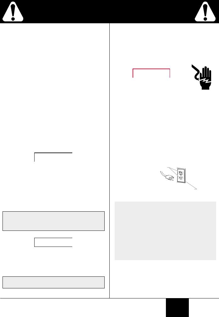
This product must be grounded. In the event of an electrical short circuit, grounding reduces the risk of electric shock by providing an escape wire for the electric current. This product is equipped with a cord having a grounding wire with an appropriate grounding plug. The plug must be plugged into an outlet that is properly installed and grounded in accordance with all local codes and ordinances.
 WARNING
Improper installation of the grounding plug can result in a risk of electric shock.
If repair or replacement of the cord or plug is necessary, do not connect the green grounding wire to either flat blade terminal. The wire with insulation having a green outer surface with or without yellow stripes is the grounding wire and must be connected to the grounding pin.
Check with a qualified electrician or serviceman if the grounding instructions are not completely understood, or if you are in doubt as to whether the product is properly grounded. Do not modify the plug provided. If the plug will not fit the outlet, have the proper outlet installed by a qualified electrician.
This product is for use on a nominal 120 volt circuit and has a grounding plug that looks like the plug illustrated below. Make sure that the product is connected to an outlet having the same configuration as the plug.
Grounded Outlet
Grounding Pin
Cover for grounded outlet box
IF YOU EXPERIENCE PROBLEMS WITH YOUR SPRAYER AT ANY TIME DURING ASSEMBLY,
OPERATION OR CLEANUP, PLEASE REFER TO THE TROUBLESHOOTING SECTION OF THIS MANUAL (PAGE 15), OR CALL CUSTOMER SERVICE AT:
1-800-686-8525
© 2002 Wagner Spray Tech - All rights reserved. 1-800-686-8525 |
3 |
English

COMPONENTS AND DESCRIPTION
COMPONENTS
The shipping carton for your painting system contains the following:
•Suction set and return tube
•Spray gun with filter
•Spray tip assembly (see chart below)
•50 foot long, 1/4 inch diameter pressure hose
•Separating Oil
CONTROLS AND FUNCTIONS
ON/OFF Switch |
................The ON/OFF switch turns the unit on |
|
and off (O=OFF, l=ON). |
Suction Set ....................... |
Fluid is drawn through the suction |
|
set into the pump. |
Fluid Section .................... |
A piston in the fluid section moves up |
|
and down to create the suction that |
|
draws fluid through the suction set. |
Spray Gun ........................ |
The spray gun controls the delivery |
|
of the fluid being pumped. The gun |
|
model you have depends on your |
sprayer model (refer to Spray Gun/Tip Chart, below).
Spray Hose ......................The spray hose connects the gun to the pump.
Return Tube......................Fluid is sent back out through the return tube to the original container.
PRIME/SPRAY Knob........The PRIME/SPRAY knob directs fluid to the spray hose when set to SPRAY or the return tube when set to PRIME. The arrows on the PRIME/SPRAY knob shows the rotation directions for PRIME and SPRAY.
The PRIME/SPRAY knob is also used to relieve pressure built up in the spray hose (Pressure Relief
Procedure, page 6)
Pressure Control Dial .......The pressure control dial controls the amount of force the pump uses to push the fluid (see graphic below for locations).
Spray Gun/Tip Chart
Sprayer |
Gun |
Tip |
Max. |
Recommended |
Model |
Model |
Size |
Size |
Filter |
1420 |
GX-06 |
.013 |
.015 |
Yellow (fine) |
1620 |
GX-07 |
.013 |
.015 |
Yellow (fine) |
1720 |
GX-07 |
.015 |
.017 |
Yellow (fine) |
1920 |
GX-08 |
.017 |
.019 |
White (medium) |
2120 |
GX-10 |
.017 |
.021 |
White (medium) |
Hose |
|
|
bracket |
|
|
|
|
|
Handle |
|
|
Motor |
|
|
housing |
|
|
Lubricating |
|
|
area (on front |
|
|
of face plate |
|
ON/OFF |
|
|
|
Pail bracket |
|
switch |
|
O = OFF |
|
|
|
|
Spray hose |
|
l = ON |
|
|
Pressure Control Dial
Rear of motor shroud, 1420, 1620, 1720, and 1920 models.
Spray hose port
Front face plate, 2120 model
Pressure Control Dial
PRIME/SPRAY knob PRIME position SPRAY position
PRIME |
SPRAY |
PRIME |
|
|
|
|
|
SPRAY |
Spray |
|
Fluid |
PRIME/ |
|
SPRAY |
||
|
section |
||
tip |
|
knob |
|
|
|
||
Spray |
|
|
|
gun |
|
|
|
Return |
|
tube |
O |
|
|
|
l |
Suction tube
 Suction set screen
English Customer Service: 800-686-8525 4 |
© 2002 Wagner Spray Tech - All rights reserved. |
SETUP--ASSEMBLING THE SPRAYER
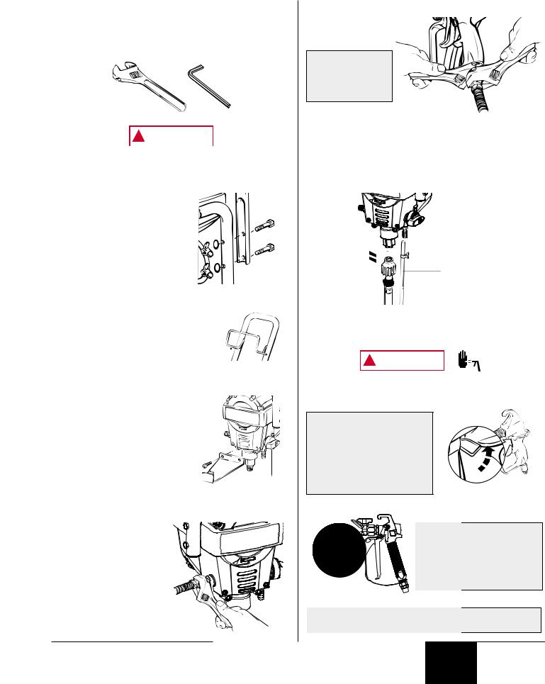
TOOLS NEEDED FOR SETUP
•Two adjustable wrenches
•3/16” allen wrench
•Extension cord (refer to Important Electrical Information
(page 3).
 WARNING
Do not plug in the unit until setup is complete.
ATTACHING THE HANDLE (CART MODEL)
1. Position the handle against the cart so that the holes in the handle line up with the holes in the cart.
2. Insert the bolts through the holes in the handle and cart and locking washers.
3.Tighten the wing nuts onto the bolts by hand.
ATTACHING THE HOSE BRACKET (CART MODEL)
1.Insert the ends of the hose bracket into the holes of the handle as
shown.
ATTACHING THE PAIL BRACKET (CART MODEL)
1. Position the pail bracket against the unit so that the holes in the unit line up with the holes in the bracket.
2. Insert the bolts through the holes in the bracket and the unit.
3. Tighten the bolts with a 3/16” allen wrench.
ATTACHING THE PAINT HOSE
1.Thread the high pressure hose to the paint hose port.
2.Tighten with an adjustable wrench.
3. Remove pusher stem from inlet valve.
ATTACHING THE SPRAY GUN
1. Thread spray gun onto the other end of the hose.
Hold the gun with one adjustable wrench, and tighten with the other.
ATTACHING THE SUCTION SET & RETURN TUBE
1.Attach the suction tube to the inlet valve and tighten firmly by hand. Be sure that the threads are straight so that the fitting turns freely.
2.Press the return tube onto the return tube fitting.
3.Squeeze clip over the return tube fitting to secure return tube.
Return tube
 fitting

 Inlet valve
 Clip
Clip
Return tube

 Suction set
LOCKING AND UNLOCKING THE SPRAY GUN
 WARNING
Always lock the trigger off when attaching the spray tip or when the spray gun is not in use. Refer to Spray Gun/Tip Chart on page 4 to determine the gun model you have.
GX-06/07
GUN MODELS GX-06 AND
GX-07
The gun is secured when the trigger lock is at a 90° angle (perpendicular) to the trigger in either direction.
Gun locked (gun will not spray)
GX-08/10
GUN MODELS GX-08 AND
GX-10
To lock the gun, turn the trigger lock forward and slightly down until it stops.
Gun locked (gun will not spray)
The spray tip SHOULD NOT be attached until after the sprayer and paint hose have been purged and primed.
© 2002 Wagner Spray Tech - All rights reserved. |
5 |
Customer Service: 800-686-8525 |
English |
BEFORE YOU BEGIN
This column contains instructions that will be repeated throughout this manual.
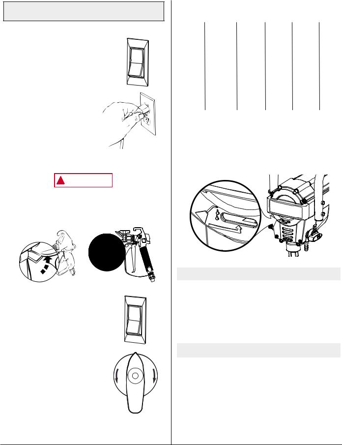
PLUGGING IN THE SPRAYER
1. |
Check that the ON/OFF |
o |
|
switch is in the OFF |
|
|
|
|
|
position. |
|
2. |
Plug the sprayer into a |
|
|
heavy duty grounded |
|
|
extension cord. Refer to |
|
|
Important Electrical |
|
|
Information, page 3). |
|
PRESSURE RELIEF PROCEDURE
 WARNING
Be sure to follow the pressure relief procedure (page 6) when shutting the unit off FOR ANY PURPOSE. This procedure is used to relieve pressure from the spray hose.
1. Lock the spray gun off.
GX-06/07
|
|
GX-08/10 |
|
2. |
Flip the ON/OFF switch to |
|
o |
|
the OFF (O) position. |
|
|
3. |
Unlock the spray gun, |
|
|
|
turn the PRIME/SPRAY |
|
|
|
knob to PRIME, and |
PRIME |
SPRAY |
|
paint bucket. |
||
|
trigger spray gun into |
|
|
4. |
Lock the spray gun. |
|
|
PAINT STRAINING
It is recommended that in order to avoid premature tip and gun plugging you should strain your paint before spraying. Follow manufacturer’s recommendations.
CHOOSING THE CORRECT SPRAY GUN FILTER
Use the proper gun filter based on the tip size being used.
Part No. |
Tip Size |
Filter |
Mesh |
Color of |
Qty. |
|
|
Type |
Number |
Filter |
|
|
|
|
|
Body |
|
0154918 |
.011 |
Extrafine |
180 mesh |
red |
2 pack |
|
|
|
0.084 mm |
|
|
|
|
|
|
|
|
0154675 |
.013 - .015 |
Fine |
100 mesh |
yellow |
2 pack |
|
|
|
0.140 mm |
|
|
|
|
|
|
|
|
0154842 |
.017 - .023 |
Medium |
50 mesh |
white |
2 pack |
|
|
|
0.315 mm |
|
|
|
|
|
|
|
|
BEFORE YOU PRIME THE SPRAYER
Before priming, squirt a teaspoon of separating oil (P/N 0279920 included with unit) into the indicated area. Light household oil can be substituted if necessary. Do not put more than a teaspoon into the lubricating area. Too much oil will leak down into your paint.
IF YOUR UNIT IS NEW. . .
All units are performance-tested at the factory and are shipped with test fluid in the fluid section to prevent corrosion during shipment and storage.
•Whether you are going to spray latex or oil-based paints, this fluid must be purged and thoroughly cleaned out of the system (follow Purging and Priming the Pump steps, page 7).
IF YOUR UNIT HAS ALREADY BEEN USED. . .
If the pump has already been used you will need to purge the water or solvent used in cleanup and storage.
English |
Customer Service: 800-686-8525 6 |
© 2002 Wagner Spray Tech - All rights reserved. |
|
|
|
 Loading...