


 Loading...
CT-400 CHASSIS
THIRTEEN-SLOT VXIBUS CHASSIS
USER’S MANUAL
P/N: 82-0050-000
Released December 21, 2007
VXI Technology, Inc.
2031 Main Street
Irvine, CA 92614-6509
(949) 955-1894
.
bus

2

www.vxitech.com
TABLE OF CONTENTS |
|
INTRODUCTION |
|
Certification ......................................................................................................................................................... |
5 |
Warranty .............................................................................................................................................................. |
5 |
Limitation of Warranty ........................................................................................................................................ |
5 |
Restricted Rights Legend ..................................................................................................................................... |
5 |
DECLARATION OF CONFORMITY ................................................................................................................................ |
6 |
GENERAL SAFETY INSTRUCTIONS.............................................................................................................................. |
7 |
Terms and Symbols.............................................................................................................................................. |
7 |
Warnings.............................................................................................................................................................. |
7 |
SUPPORT RESOURCES ................................................................................................................................................ |
9 |
SECTION 1 ................................................................................................................................................................... |
11 |
INTRODUCTION ........................................................................................................................................................ |
11 |
Introduction........................................................................................................................................................ |
11 |
General Description ........................................................................................................................................... |
12 |
Power Supplies................................................................................................................................................... |
12 |
Backplane........................................................................................................................................................... |
12 |
Cooling............................................................................................................................................................... |
12 |
CT-400 Mainframe Features.............................................................................................................................. |
13 |
Voltage Indicator LEDs ..................................................................................................................................... |
14 |
Rear Panel Monitor / Control Connector ........................................................................................................... |
15 |
CT-400 Specifications ....................................................................................................................................... |
16 |
SECTION 2 ................................................................................................................................................................... |
25 |
INSTALLATION ......................................................................................................................................................... |
25 |
Introduction........................................................................................................................................................ |
25 |
Power Requirements .......................................................................................................................................... |
25 |
Connecting the Mainframe to Earth Ground...................................................................................................... |
26 |
Air Flow Requirements...................................................................................................................................... |
26 |
Installing the Card Shield Option....................................................................................................................... |
27 |
Installing Blanking Panels ................................................................................................................................. |
27 |
BENCH-TOP CT-400 USE ......................................................................................................................................... |
28 |
Overview............................................................................................................................................................ |
28 |
RACK MOUNTING THE CT-400 ................................................................................................................................ |
29 |
Overview............................................................................................................................................................ |
29 |
Assembly Preparation ........................................................................................................................................ |
29 |
Mounting the Mainframe ................................................................................................................................... |
29 |
Option 100 - Adjustable Rack Mount Flanges with Handles ............................................................................ |
30 |
Option 101 - VXIplug&play Rack Mount Kit ................................................................................................... |
32 |
Option 102 - Rack Mount Slides........................................................................................................................ |
34 |
ADDITIONAL RACK MOUNT OPTIONS ...................................................................................................................... |
36 |
Overview............................................................................................................................................................ |
36 |
Option 103 - Transparent Front Door Installation Procedure ............................................................................ |
38 |
Option 104 - Hinged Custom Front Panel Installation Procedure ..................................................................... |
40 |
Option 105/106 - 1U/2U Cable Trays Installation Procedure............................................................................ |
42 |
INSTALLATION OF VXI MODULES ........................................................................................................................... |
44 |
Overview............................................................................................................................................................ |
44 |
DISCONNECTING THE MAINFRAME .......................................................................................................................... |
45 |
CT-400 Preface |
3 |

|
VXI Technology, Inc. |
SECTION 3 ................................................................................................................................................................... |
47 |
OPERATION.............................................................................................................................................................. |
47 |
Introduction........................................................................................................................................................ |
47 |
Remote Power Control....................................................................................................................................... |
47 |
CT-400 Monitor Board ...................................................................................................................................... |
48 |
CT-400 Monitor Board - Signals ....................................................................................................................... |
49 |
Connector J210.............................................................................................................................................. |
49 |
Connector J211.............................................................................................................................................. |
50 |
SECTION 4 ................................................................................................................................................................... |
51 |
SERVICE INFORMATION ........................................................................................................................................... |
51 |
Introduction........................................................................................................................................................ |
51 |
Cleaning the Air Filters...................................................................................................................................... |
52 |
Cleaning the Power Supply Fan Filter .......................................................................................................... |
52 |
Cleaning the Module Fan Filter .................................................................................................................... |
53 |
Power Supply Replacement Procedure .............................................................................................................. |
54 |
INDEX .......................................................................................................................................................................... |
57 |
4 |
CT-400 Preface |

www.vxitech.com
CERTIFICATION
VXI Technology, Inc. (VTI) certifies that this product met its published specifications at the time of shipment from the factory. VTI further certifies that its calibration measurements are traceable to the United States National Institute of Standards and Technology (formerly National Bureau of Standards), to the extent allowed by that organization’s calibration facility, and to the calibration facilities of other International Standards Organization members.
WARRANTY
The product referred to herein is warranted against defects in material and workmanship for a period of three years from the receipt date of the product at customer’s facility. The same warranty applies to the power supply for a period of one year. The sole and exclusive remedy for breach of any warranty concerning these goods shall be repair or replacement of defective parts, or a refund of the purchase price, to be determined at the option of VTI.
For warranty service or repair, this product must be returned to a VXI Technology authorized service center. The product shall be shipped prepaid to VTI and VTI shall prepay all returns of the product to the buyer. However, the buyer shall pay all shipping charges, duties, and taxes for products returned to VTI from another country.
VTI warrants that its software and firmware designated by VTI for use with a product will execute its programming when properly installed on that product. VTI does not however warrant that the operation of the product, or software or firmware will be uninterrupted or error free.
LIMITATION OF WARRANTY
The warranty shall not apply to defects resulting from improper or inadequate maintenance by the buyer, buyersupplied products or interfacing, unauthorized modification or misuse, operation outside the environmental specifications for the product, or improper site preparation or maintenance.
VXI Technology, Inc. shall not be liable for injury to property other than the goods themselves. Other than the limited warranty stated above, VXI Technology, Inc. makes no other warranties, express, or implied, with respect to the quality of product beyond the description of the goods on the face of the contract. VTI specifically disclaims the implied warranties of merchantability and fitness for a particular purpose.
RESTRICTED RIGHTS LEGEND
Use, duplication, or disclosure by the Government is subject to restrictions as set forth in subdivision (b)(3)(ii) of the Rights in Technical Data and Computer Software clause in DFARS 252.227-7013.
VXI Technology, Inc.
2031 Main Street
Irvine, CA 92614-6509 U.S.A.
CT-400 Preface |
5 |

VXI Technology, Inc.
D E C L A R A T I O N O F C O N F O R M I T Y
Declaration of Conformity According to ISO/IEC Guide 22 and EN 45014
MANUFACTURER’S NAME |
VXI Technology, Inc. |
MANUFACTURER’S ADDRESS |
2031 Main Street |
|
Irvine, California 92614-6509 |
PRODUCT NAME |
Thirteen-Slot VXIbus Chassis |
MODEL NUMBER(S) |
CT-400 |
PRODUCT OPTIONS |
All |
PRODUCT CONFIGURATIONS |
All |
VXI Technology, Inc. declares that the aforementioned product conforms to the requirements of the Low Voltage Directive 73/23/EEC and the EMC Directive 89/366/EEC (inclusive 93/68/EEC) and carries the “CE” mark accordingly. The product has been designed and manufactured according to the following specifications:
SAFETY |
EN61010 (2001) |
EMC |
EN61326 (1997 w/A1:98) Class A |
|
CISPR 22 (1997) Class A |
|
VCCI (April 2000) Class A |
|
ICES-003 Class A (ANSI C63.4 1992) |
|
AS/NZS 3548 (w/A1 & A2:97) Class A |
|
FCC Part 15 Subpart B Class A |
|
EN 61010-1:2001 |
I hereby declare that the aforementioned product has been designed to be in compliance with the relevant sections of the specifications listed above as well as complying with all essential requirements of the Low Voltage Directive.
December 2007
Steve Mauga, QA Manager
6 |
CT-400 Preface |
www.vxitech.com
GENERAL SAFETY INSTRUCTIONS
Review the following safety precautions to avoid bodily injury and/or damage to the product. These precautions must be observed during all phases of operation or service of this product. Failure to comply with these precautions, or with specific warnings elsewhere in this manual, violates safety standards of design, manufacture, and intended use of the product.
Service should only be performed by qualified personnel.
TERMS AND SYMBOLS
These terms may appear in this manual:
Indicates that a specific WARNING or CAUTION follows.
WARNING |
Indicates that a procedure or condition may cause bodily injury or death. |
CAUTION |
Indicates that a procedure or condition could possibly cause damage to |
|
equipment or loss of data. |
These symbols may appear on the product:
WARNING |
Indicates that a procedure or condition may cause bodily injury or death. |
ATTENTION - Important safety instructions
!
Frame or chassis ground
Alternating Current (ac)
Indicates that the product was manufactured after August 13, 2005. This mark is
placed in accordance with EN 50419, Marking of electrical and electronic equipment in accordance with Article 11(2) of Directive 2002/96/EC (WEEE).
End-of-life product can be returned to VTI by obtaining an RMA number. Fees
for take-back and recycling will apply if not prohibited by national law.
WARNINGS
Follow these precautions to avoid injury or damage to the product:
Use Proper Power Cord |
To avoid hazard, only use the power cord specified for this product. |
Use Proper Power Source |
To avoid electrical overload, electric shock, or fire hazard, do not |
|
use a power source that applies other than the specified voltage. |
CT-400 Preface |
7 |

|
|
VXI Technology, Inc. |
WARNINGS (CONT.) |
|
|
Use Proper Fuse |
To avoid fire hazard, only use the type and rating fuse specified for |
|
|
this product. |
|
Avoid Electric Shock |
To avoid electric shock or fire hazard, do not operate this product |
|
|
with the covers removed. Do not connect or disconnect any cable, |
|
|
probes, test leads, etc. while they are connected to a voltage source. |
|
|
Remove all power and unplug unit before performing any service. |
|
|
Service should only be performed by qualified personnel. |
|
Ground the Product |
This product is grounded through the grounding conductor of the |
|
|
power cord. To avoid electric shock, the grounding conductor must |
|
|
be connected to earth ground. |
|
Operating Conditions |
To avoid injury, electric shock or fire hazard: |
|
|
- |
Do not operate in wet or damp conditions. |
|
- |
Do not operate in an explosive atmosphere. |
|
- |
Operate or store only in specified temperature range. |
|
- |
Provide proper clearance for product ventilation to prevent |
|
|
overheating. |
|
- |
DO NOT operate if you suspect there is any damage to this |
|
|
product. Product should be inspected or serviced only by |
|
|
qualified personnel. |
Improper Use |
The operator of this instrument is advised that if the equipment is |
|
|
used |
in a manner not specified in this manual, the protection |
provided by the equipment may be impaired. Conformity is checked by inspection.
8 |
CT-400 Introduction |

www.vxitech.com
SUPPORT RESOURCES
Support resources for this product are available on the Internet and at VXI Technology customer support centers.
VXI Technology
World Headquarters
VXI Technology, Inc.
2031 Main Street
Irvine, CA 92614-6509
Phone: (949) 955-1894
Fax: (949) 955-3041
VXI Technology
Cleveland Instrument Division
5425 Warner Road
Suite 13
Valley View, OH 44125
Phone: (216) 447-8950
Fax: (216) 447-8951
VXI Technology
Lake Stevens Instrument Division
VXI Technology, Inc.
1924 - 203 Bickford
Snohomish, WA 98290
Phone: (425) 212-2285
Fax: (425) 212-2289
Technical Support
Phone: (949) 955-1894
Fax: (949) 955-3041
E-mail: support@vxitech.com
Visit http://www.vxitech.com for worldwide support sites and service plan information.
CT-400 Preface |
9 |

VXI Technology, Inc.
10 |
CT-400 Introduction |
www.vxitech.com
SECTION 1
INTRODUCTION
INTRODUCTION
This section contains a general description of operating features of the CT-400. A list of mainframe features follows the description, which is then followed by a brief discussion of the options available for the CT-400.
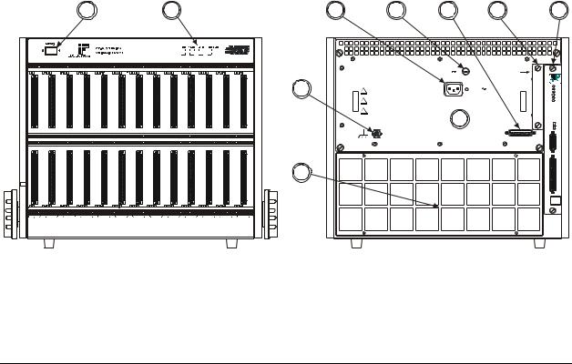
FIGURE 1-1: CT-400 THIRTEEN-SLOT MAINFRAME WITH MODULES
CT-400 Introduction |
11 |

VXI Technology, Inc.
GENERAL DESCRIPTION
The CT-400 mainframe is a C-size, thirteen-slot, VXIbus compatible mainframe that conforms fully to VXIbus Specification Revision 1.4. The mainframe employs a multi-layer backplane to ensure premium VXIbus and VMEbus performance and provides all power supplies required by the VXIbus specification.
The CT-400 mainframe contains thirteen slots in the card cage, twelve of which are available for use by VXIbus compatible instruments. The thirteenth slot in the card cage (slot 0) is typically dedicated to the VXIbus Resource Manager.
POWER SUPPLIES
The CT-400 is designed to operate at line frequencies from 47 Hz to 440 Hz and is factory preset to operate at a nominal line voltage of 115 V ac. The ac input is both auto-voltage and autofrequency ranging and may be reconfigured to operate at a nominal 220 V ac by simply changing the fuse located at the rear of the chassis.
The power supply assembly is completely removable from the rear of the mainframe. The assembly is short-circuit, over-voltage, reverse-voltage and thermal-shutdown protected. In addition, all supply lines are monitored and displayed on the front panel to provide user-feedback of correct operation.
BACKPLANE
The CT-400 has a jumperless auto-configurable backplane with automatic bus grant and IACK jumpering. There is also a custom power sub-panel to distribute all the supply lines across the backplane, as well as a 10-layer stripline construction that minimizes crosstalk.
COOLING
The airflow design uses a pressurized plenum system with a baffling system to guarantee enough cooling capacity. The cooling direction for the VXI instruments is air is drawn through the back of the mainframe and exhausted out both sides at the top. The power supply is cooled by an airflow that moves from left (if facing the mainframe) to right.
12 |
CT-400 Introduction |
www.vxitech.com
|
CT-400 MAINFRAME FEATURES |
|
|
|
|
|
|
|
|
|
|
|
|
FRONT PANEL FEATURES |
|
|
|
|
|
|
POWER SWITCH |
|
|
|
|
|
|
Feature 1 |
When elevated, the mainframe is in standby mode, where power is supplied to |
|
||||
|
the mainframe, but not to the VXI modules. |
|
|
|
|
|
|
When depressed, power is supplied to both mainframe and VXI modules. |
|
||||
VOLTAGE MONITOR INDICATORS |
|
|
|
|
|
|
Feature 2 |
Indicates whether specific backplane voltages are within specifications. See |
|
||||
|
Figure 1-3 for details. |
|
|
|
|
|
|
|
|
|
|
|
|
REAR PANEL FEATURES |
|
|
|
|
|
|
MODULE FAN FILTER |
|
|
|
|
|
|
Feature 3 |
Replaceable component that filters the air that cools the plug-in modules. |
|
||||
CHASSIS GROUND TERMINAL |
|
|
|
|
|
|
Feature 4 |
Used to electrical ground the mainframe. |
|
|
|
|
|
J200 CONNECTOR |
|
|
|
|
|
|
Feature 5 |
AC power receptacle. |
|
|
|
|
|
F200 CONNECTOR |
|
|
|
|
|
|
Feature 6 |
Fuse location. |
|
|
|
|
|
J210 CONNECTOR |
|
|
|
|
|
|
Feature 7 |
Monitor / Control Connector. |
|
|
|
|
|
POWER SUPPLY FAN FILTER |
|
|
|
|
|
|
Feature 8 |
Replaceable component that filters the air that cools the power supply. |
|
||||
MONITOR BOARD / J211 CONNECTOR |
|
|
|
|
|
|
Feature 9 |
Provides monitoring of the mainframe’s operation and environment. |
|
||||
|
(See Section 1 for more details.) |
|
|
|
|
|
POWER SUPPLY |
|
|
|
|
|
|
Feature 10 |
Replaceable power supply unit. |
|
|
|
|
|
1 |
2 |
5 |
6 |
7 |
8 |
9 |
0 |
1 |
|
CT-400 SERIES |
+5V +12V +24V |
+5V Stby |
|
|
|
VXI MAINFRAME |
-5.2V -12V -24V |
-2V |
|
|
|
|
||
|
|
|
|
Voltage Monitors |
|
bus
4 |
! |
WARNING - DO NOT REMOVE THIS POWER MODULE |
WHILE THIS INSTRUMENTHAS AC POWER APPLIED |
||
|
|
WARNING - THE GROUNDING CONNECTION IN THE |
|
! |
POWER CORD MUST BE CONNECTED TO ENSURE |
|
PROTECTION FROM ELECTRICAL SHOCK. |
|
|
! |
WARNING - TO AVOID ELECTRICALSHOCK, DISCONNECT |
|
AC POWER CORD PRIOR TO REPLACING FUSE. |
|
|
|
CAUTION - FOR CONTINUED FIRE PROTECTION |
|
|
REPLACE ONLY WITH A FUSE OF THE CORRECT |
|
|
VOLTAGE AND RATING. |
F200 |
|
|
15A T 250 (VAC) |
REMOVE COVER TO |
|
|
SERVICE AIR FILTER |
|
J200 |
PWS |
TEMP |
100 - 240 VAC |
AMB |
TEMP |
15 A MAX. |
PWS |
PWR |
47 -63 Hz |
||
|
PWS |
VOLT |
|
PWS |
CUR |
|
FAN |
SPEED |
10 |
VAR |
|
|
FAN SPEED |
|
|
HIGH |
|
|
LOW |
|
|
J201 |
|
|
MON ITOR / CONTR OL |
|
J211
3 |
J210 |
|
|
1 |
|
2 |
|
3 |
|
4 |
|
5 |
|
6 |
|
7 |
|
8 |
|
9 |
|
1 0 |
|
1 1 |
|
1 2 |
FIGURE 1-2: MAINFRAME FEATURE LOCATIONS
CT-400 Introduction |
13 |

VXI Technology, Inc.
VOLTAGE INDICATOR LEDS
The power supply lines are monitored and displayed on the front panel, providing information pertaining to the chassis operational status.
Voltage Monitor LEDs |
|
|
|
|
|
|
|
Green |
: Within Voltage Specifications |
|
|
|
|
|
|
Not Lit : Under Voltage |
|
|
|
|
|
|
|
Red |
: Over Voltage |
|
|
|
|
|
|
0 |
1 |
CT-400 SERIES |
+5V |
+12V |
+24V |
+5V Stby |
|
|
|
|
|
|
|||
VXI MAINFRAME |
|
|
|
|
|
||
|
|
-5.2V |
-12V |
-24V |
-2V |
bus |
|
|
|
|
|||||
|
|
|
|
||||
Voltage Monitors
|
|
|
|
|
|
|
|
|
|
|
|
|
|
|
|
|
|
|
|
|
|
|
|
|
|
1 |
2 |
3 |
4 |
5 |
6 |
7 |
8 |
9 |
10 |
11 |
12 |
FIGURE 1-3: FRONT PANEL VOLTAGE INDICATORS
14 |
CT-400 Introduction |

www.vxitech.com
REAR PANEL MONITOR / CONTROL CONNECTOR
The 25-pin Monitor/Control Connector (see Figure 1-2) provides access to the backplane voltages and other signals. The following table shows a pinout/signal list along with a brief description of each. Refer to the pin locations in Figure 1-4.
|
|
TABLE 1-1: MONITOR / CONTROL CONNECTOR PINOUT ASSIGNMENTS |
||||
|
|
|
|
|
|
|
|
|
PIN |
SIGNAL |
|
DESCRIPTION |
|
|
|
|
|
|
|
|
|
|
1 |
-24 VMON |
|
VXIbus Voltage Monitor Output |
|
|
|
2 |
GND |
|
Logic Ground |
|
|
|
3 |
-2 VMON |
|
VXIbus Voltage Monitor Output |
|
|
|
4 |
GND |
|
Logic Ground |
|
|
|
5 |
+24 IMON |
|
Power Supply Current Monitor Output |
|
|
|
6 |
-12 IMON |
|
Power Supply Current Monitor Output |
|
|
|
7 |
-2 IMON |
|
Power Supply Current Monitor Output |
|
|
|
8 |
-5.2 VMON |
|
VXIbus Voltage Monitor Output |
|
|
|
9 |
RSV |
|
Reserved |
|
|
|
10 |
+5 STANDBY |
|
VXIbus +5 V Standby Input |
|
|
|
11 |
+5 VMON |
|
VXIbus Voltage Monitor Output |
|
|
|
12 |
ACFAIL* |
|
VXIbus ACFAIL* Input or Monitor Output (see note) |
|
|
|
13 |
RSV |
|
Reserved |
|
|
|
14 |
GND |
|
Logic Ground |
|
|
|
15 |
-12 VMON |
|
VXIbus Voltage Monitor Output |
|
|
|
16 |
+24 VMON |
|
VXIbus Voltage Monitor Output |
|
|
|
17 |
+12 VMON |
|
VXIbus Voltage Monitor Output |
|
|
|
18 |
+12 IMON |
|
Power Supply Current Monitor Output |
|
|
|
19 |
-24 IMON |
|
Power Supply Current Monitor Output |
|
|
|
20 |
-5.2 IMON |
|
Power Supply Current Monitor Output |
|
|
|
21 |
+5 IMON |
|
Power Supply Current Monitor Output |
|
|
|
22 |
+5 STANDBY |
|
VXIbus +5 V Standby Input |
|
|
|
23 |
R INHIBIT* |
|
Power Supply Remote Inhibit Input |
|
|
|
24 |
GND |
|
Logic Ground |
|
|
|
TABLE 1-2: MONITOR / CONTROL CONNECTOR PINOUT ASSIGNMENTS |
||||
|
|
|||||
NOTE |
Refer to VXIbus and VMEbus specifications for details on using the ACFAIL* and SYSRESET* |
|||||
|
signals |
|
|
|
|
|
|
|
|
Pin 13 |
Pin 1 |
||
Pin 25 |
Pin 14 |
FIGURE 1-4: DETAIL - MONITOR / CONTROL CONNECTOR PIN LOCATIONS
CT-400 Introduction |
15 |

VXI Technology, Inc.
CT-400 SPECIFICATIONS
GENERAL SPECIFICATIONS
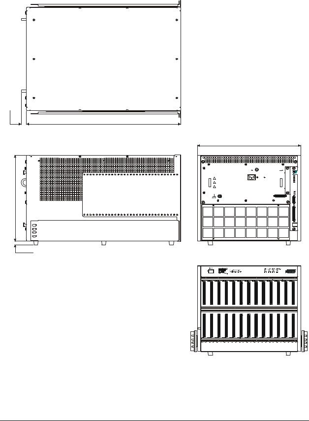
SIZE
16.7" (424.18 mm) W x 14.00" (355.60 mm) H x 25.00" D (635.00 mm) Thirteen C-size VXIbus card slots
WEIGHT
< 50 lb (11.3 kg)
VXIBUS VERSION
1.4
MTBF
100,000 hr
MTTR
5 min
ENVIRONMENTAL SPECIFICATIONS
OPERATING LOCATION
|
This chassis should be operated indoors in a controlled environment, protected |
|
from exposure to the elements (i.e. direct sunlight, precipitation, wind, etc.) |
TEMPERATURE |
|
Operating |
0 °C to +55 °C |
Storage |
-40 °C to +71 °C |
HUMIDITY |
|
Operating |
Up to 95% (non-condensing) at up to 30 °C; up to 45% at up to 55 °C |
Non-operating |
Up to 95% (non-condensing) at up to 55 °C |
Altitude |
|
Operating |
15,000 ft (4570 m) |
Non-Operating |
40,000 ft (12,190 m) |
Random Vibration* |
|
Operating |
0.27 g-rms total from 5 Hz to 55 Hz |
Non-Operating |
2.28 g-rms total from 5 Hz to 55 Hz |
* Three axis, 30 min total, 10 min per axis.
Functional Shock
Operating |
Half sine, 30 g, 11 ms duration |
|
Meets functional shock requirements of MIL-T-28800E, Type III, Class 5 |
|
|
COOLING SPECIFICATIONS |
|
COOLING REQUIREMENTS |
|
|
> 100 W/slot |
COOLING MODES |
|
|
Three cooling modes are available for the CT-400 mainframe. High or low |
|
speed cooling modes can be selected by moving the Fan Speed switch at the |
|
rear of the mainframe. The variable cooling speed mode determines fan speed |
|
as a function of ambient temperature a mainframe load. The power supply and |
|
modules are cooled by separate fans. |
AIR FLOW PATH |
|
|
Air is drawn into the mainframe from the rear and is pressurized below the |
|
cards. The air is then distributed across all slots along the total length of each |
|
slot and is exhausted through the top of the mainframe. When the mainframe is |
|
rack mounted, allow approximately 2.0 inches (5.1 cm) of clearance at the top |
|
and rear for proper airflow. |
16 |
CT-400 Introduction |

www.vxitech.com
POWER SPECIFICATIONS
POWER
Available |
1630 W |
|
|
|
||
Useable |
1000 W |
|
|
|
||
DC SUPPLY VOLTAGE |
|
|
|
|
|
|
|
A total of 1000 W may be supplied to the modules with the following |
|||||
|
maximum currents: |
|
|
|
||
|
|
|
|
|
|
|
|
|
Voltage |
|
Peak Current (IMP) |
Dynamic Current (IMD) |
|
|
|
+5 V |
|
80 A |
15 A |
|
|
|
-5.2 V |
|
60 A |
10 A |
|
|
|
-2 V |
|
30 A |
5 A |
|
|
|
+12 V |
|
17 A |
3 A |
|
|
|
-12 V |
|
17 A |
3 A |
|
|
|
+24 V |
|
12 A |
4 A |
|
|
|
-24 V |
|
12 A |
4 A |
|
OUTPUT VOLTAGE
|
|
|
|
Voltage |
|
|
Allowed Variation |
|
|
|
Ripple/Noise |
|
Induced Ripple |
|
|
|
|
|
|
|
|
|
|
DC Load |
|
Noise |
|
||
|
|
|
|
|
|
|
|
|
|
|
|
|
||
|
|
|
|
+5 V |
|
+0.25 V / -0.125 V |
|
|
50 mV |
|
50 mV |
|
||
|
|
|
|
-5.2 V |
|
-0.26 V / +0.125 V |
|
50 mV |
|
50 mV |
|
|||
|
|
|
|
-2 V |
|
-0.10 V / +0.72 V |
|
50 mV |
|
50 mV |
|
|||
|
|
|
|
+12 V |
|
+0.60 V / +0.36 V |
|
50 mV |
|
50 mV |
|
|||
|
|
|
|
-12 V |
|
-0.60 V / +0.36 V |
|
50 mV |
|
50 mV |
|
|||
|
|
|
|
+24 V |
|
+1.20 V / -0.72 V |
|
150 mV |
|
150 mV |
|
|||
|
|
|
|
-24 V |
|
-1.20 V / +0.74 V |
|
150 mV |
|
150 mV |
|
|||
|
|
|
|
|
|
|
|
|
|
|
|
|
|
|
POWER INPUT |
|
|
|
|
|
|
|
|
|
|
|
|
|
|
Input Voltage |
100 V ac minimum, 240 V ac maximum |
|
|
|
|
|||||||||
Nominal AC |
|
|
|
|
||||||||||
Frequency |
|
47 Hz - 63 Hz (47 Hz - 440 Hz with increased leakage current and reduced PFC) |
|
|||||||||||
Inrush Current |
|
< 70 A (cold start or after 1 minute cool down) |
|
|
|
|||||||||
Input Power |
|
1000 W max |
|
|
|
|
|
|
|
|
|
|||
Input Leakage |
|
< 1.24 MA @ 264 V ac, 53 Hz |
|
|
|
|
||||||||
Input Harmonics |
|
Meets EN61000-3-2 |
|
|
|
|
||||||||
Fuse |
|
15 A, 250 V, slow blow |
|
|
|
|
||||||||
90 V– 250 V Operation |
|
|
|
|
|
|||||||||
207 V– 250 V Operation |
|
10 A, 250 V, slow blow |
|
|
|
|
||||||||
PERIODIC AND RANDOM DEVIATIONS |
|
|
|
|
|
|
|
|
|
|||||
±24 V |
150 mVP-P |
|
|
|
|
|
|
|
|
|
||||
All Others |
|
50 mVP-P |
|
|
|
|
|
|
|
|
|
|||
AUXILIARY DC OUTPUTS
1.5 A each at all seven supply voltages (fused/self-healing)
POWER SUPPLY
UL, CSA, TUV approved
Shout circuit, over-voltage, reverse voltage and thermal shutdown protection
CT-400 Introduction |
17 |
VXI Technology, Inc.
TOP VIEW
0.805
(20.440)
24.900
(632.46)
13.900
(353.06)
REAR VIEW
16.699
(424.15)
|
|
F200 |
|
|
|
15AT 250 |
(VAC) |
REMOVE COVER TO |
|
|
|
|
SERVICE AIR FILTER |
|
|
|
J200 |
PWS |
TEMP |
! |
WARNING - DO NOT REMOVE THIS PO WER MODULE |
100 -240 VAC |
AMB |
TEMP |
15 AMAX. |
PWS |
PWR |
||
WHILE THIS INSTRUMENT HAS AC POWER APPLIED |
47 -63 Hz |
PWS |
VOLT |
|
|
WARNING - THE GROUNDING CONNECTION IN THE |
|
PWS |
CUR |
! |
POWER CORD MUST BE CONNECTED TO ENSURE |
|
FAN |
SPEED |
PROTECTION FROM ELECTRICAL SHOCK. |
|
|
|
|
! |
WARNING - TO AVOID ELECTRICAL SHOCK, DISCONNECT |
|
|
|
AC POW ER CORD PRIOR TO REPLACING FUSE. |
|
|
|
|
|
CAUTION - FOR CONTINUED FIRE PROTECTION |
|
FAN SPEED |
|
|
REPLACE ONLY WITH A FUSE OF THE CORRECT |
|
||
|
VOLTAGE AND RATING. |
|
HIGH |
|
VAR
LOW
J201
MONITOR / CONTROL
J211
J210
0.615
(15.620)
LEFT SIDE VIEW
FRONT VIEW
|
|
CT-400 SERIES |
+5V |
+12V +24 V |
+ 5V S tb y |
|
0 |
1 |
|
|
|
|
|
VXI MAINFRAME |
|
|
|
|
||
|
|
-5.2V -12V -24V |
-2V |
|
||
|
|
|
bus |
|||
|
|
|
Voltage Monitors |
|
||
1 |
2 |
3 |
4 |
5 |
6 |
7 |
8 |
9 |
10 |
11 |
12 |
* Note: Measurements in parenthesis are in millimeters
FIGURE 1-5: CT-400 DIMENSIONAL DIAGRAM
18 |
CT-400 Introduction |
Loading...