


Vulcan-Hart 160L, VG48, 36L, VG260, VG24 User Manual
...INSTALLATION &
OPERATION MANUAL
GAS RESTAURANT RANGES 90 SERIES AND VG SERIES
MODEL |
|
|
|
|
|
|
|
|
|
24L |
ML-52947 |
|
|
|
36L |
ML-52948 |
|
|
|
481L |
ML-52950 |
|
|
|
148L |
ML-52951 |
|
|
|
60L |
ML-52952 |
|
|
|
260L |
ML-52954 |
|
|
|
VG24 |
ML-114553 |
|
|
|
VG36 |
ML-114554 |
|
|
|
VG60 |
ML-114555 |
|
|
|
VG260 |
ML-114557 |
|
|
|
PRIOR MLS COVERED |
|
MODEL VG36 |
|
|
IN THE CATALOG |
|
|
|
|
|
|
|
|
|
48L |
ML-52949 |
|
|
|
160L |
ML-52953 |
|
|
|
VG48 |
ML-114957 |
|
|
|
VG160 |
ML-114556 |
|
MODEL 36L |
|
|
|
|
|
|
|
|
|
|
|
For additional information on Vulcan-Hart or to locate an authorized parts and service provider in your area, visit our website at www.vulcanhart.com
VULCAN-HART |
P.O. BOX 696, LOUISVILLE, KY 40201-0696 |
|
DIVISION OF ITW FOOD EQUIPMENT GROUP, LLC |
TEL. (502) 778-2791 |
|
|
|
|
F-31055 Rev. D (02-04)
IMPORTANT FOR YOUR SAFETY
THIS MANUAL HAS BEEN PREPARED FOR PERSONNEL QUALIFIED TO INSTALL GAS EQUIPMENT, WHO SHOULD PERFORM THE INITIAL FIELD START-UP AND ADJUSTMENTS OF THE EQUIPMENT COVERED BY THIS MANUAL.
POST IN A PROMINENT LOCATION THE INSTRUCTIONS TO BE FOLLOWED IN THE EVENT THE SMELL OF GAS IS DETECTED. THIS INFORMATION CAN BE OBTAINED FROM THE LOCAL GAS SUPPLIER.
IMPORTANT
IN THE EVENT A GAS ODOR IS DETECTED, SHUT
DOWN UNITS AT MAIN SHUTOFF VALVE AND
CONTACT THE LOCAL GAS COMPANY OR GAS
SUPPLIER FOR SERVICE.
FOR YOUR SAFETY
DO NOT STORE OR USE GASOLINE OR OTHER
FLAMMABLE VAPORS OR LIQUIDS IN THE
VICINITY OF THIS OR ANY OTHER APPLIANCE.
WARNING
IMPROPER INSTALLATION, ADJUSTMENT,
ALTERATION, SERVICE OR MAINTENANCE CAN
CAUSE PROPERTY DAMAGE, INJURY OR DEATH.
READ THE INSTALLATION, OPERATING AND
MAINTENANCE INSTRUCTIONS THOROUGHLY
BEFORE INSTALLING OR SERVICING THIS
EQUIPMENT.
IN THE EVENT OF A POWER FAILURE, DO NOT
ATTEMPT TO OPERATE THIS DEVICE.
— 2 —

TABLE OF CONTENTS
GAS RESTAURANT RANGE MODELS . . . . . . . . . . . . . . . . . . . . . . . . . . . . . . . . . . . . . . . . . . . . . . 4
OPTIONAL FIELD INSTALLABLE ACCESSORIES . . . . . . . . . . . . . . . . . . . . . . . . . . . . . . . . . . . . 5
GENERAL . . . . . . . . . . . . . . . . . . . . . . . . . . . . . . . . . . . . . . . . . . . . . . . . . . . . . . . . . . . . . . . . . . . . . |
6 |
INSTALLATION . . . . . . . . . . . . . . . . . . . . . . . . . . . . . . . . . . . . . . . . . . . . . . . . . . . . . . . . . . . . . . . . . 6
Uncrating . . . . . . . . . . . . . . . . . . . . . . . . . . . . . . . . . . . . . . . . . . . . . . . . . . . . . . . . . . . . . . . . 6
Location . . . . . . . . . . . . . . . . . . . . . . . . . . . . . . . . . . . . . . . . . . . . . . . . . . . . . . . . . . . . . . . . . 6
Installation Codes and Standards . . . . . . . . . . . . . . . . . . . . . . . . . . . . . . . . . . . . . . . . . . . . . 7
Assembly . . . . . . . . . . . . . . . . . . . . . . . . . . . . . . . . . . . . . . . . . . . . . . . . . . . . . . . . . . . . . . . . 7
Ranges Mounted on Casters . . . . . . . . . . . . . . . . . . . . . . . . . . . . . . . . . . . . . . . . . . . 7
Bumper Bars (Convection Oven Ranges Only) . . . . . . . . . . . . . . . . . . . . . . . . . . . . 8
Installation of Broiler/Griddle Bricks . . . . . . . . . . . . . . . . . . . . . . . . . . . . . . . . . . . . . 8
Installation of Standard Griddle Top Bricks . . . . . . . . . . . . . . . . . . . . . . . . . . . . . . . 8
Installation of Hot Top Bricks . . . . . . . . . . . . . . . . . . . . . . . . . . . . . . . . . . . . . . . . . 11
Backsplash . . . . . . . . . . . . . . . . . . . . . . . . . . . . . . . . . . . . . . . . . . . . . . . . . . . . . . . . 11
Leveling . . . . . . . . . . . . . . . . . . . . . . . . . . . . . . . . . . . . . . . . . . . . . . . . . . . . . . . . . . . . . . . . 14
Gas Connections . . . . . . . . . . . . . . . . . . . . . . . . . . . . . . . . . . . . . . . . . . . . . . . . . . . . . . . . . 14
Testing the Gas Supply System . . . . . . . . . . . . . . . . . . . . . . . . . . . . . . . . . . . . . . . . . . . . . 15
Flue Connections . . . . . . . . . . . . . . . . . . . . . . . . . . . . . . . . . . . . . . . . . . . . . . . . . . . . . . . . . 16
Electrical Connections . . . . . . . . . . . . . . . . . . . . . . . . . . . . . . . . . . . . . . . . . . . . . . . . . . . . . 16
OPERATION . . . . . . . . . . . . . . . . . . . . . . . . . . . . . . . . . . . . . . . . . . . . . . . . . . . . . . . . . . . . . . . . . . 17
Controls . . . . . . . . . . . . . . . . . . . . . . . . . . . . . . . . . . . . . . . . . . . . . . . . . . . . . . . . . . . . . . . . 17
Before First Use . . . . . . . . . . . . . . . . . . . . . . . . . . . . . . . . . . . . . . . . . . . . . . . . . . . . . . . . . . 17
Lighting and Shutting Down Pilots . . . . . . . . . . . . . . . . . . . . . . . . . . . . . . . . . . . . . . . . . . . 17
Rack Arrangement - Standard Oven . . . . . . . . . . . . . . . . . . . . . . . . . . . . . . . . . . . . . . . . . 22
Rack Arrangement - Convection Oven . . . . . . . . . . . . . . . . . . . . . . . . . . . . . . . . . . . . . . . . 22
Inserting and Removing Standard and Convection Oven Racks . . . . . . . . . . . . . . . . . . . 23
Preheating . . . . . . . . . . . . . . . . . . . . . . . . . . . . . . . . . . . . . . . . . . . . . . . . . . . . . . . . . . . . . . 24
Loading and Unloading Standard and Convection Ovens . . . . . . . . . . . . . . . . . . . . . . . . 24
Cooking Chart . . . . . . . . . . . . . . . . . . . . . . . . . . . . . . . . . . . . . . . . . . . . . . . . . . . . . . . . . . . 25
Cleaning . . . . . . . . . . . . . . . . . . . . . . . . . . . . . . . . . . . . . . . . . . . . . . . . . . . . . . . . . . . . . . . . 28
MAINTENANCE . . . . . . . . . . . . . . . . . . . . . . . . . . . . . . . . . . . . . . . . . . . . . . . . . . . . . . . . . . . . . . . . 31
Lubrication . . . . . . . . . . . . . . . . . . . . . . . . . . . . . . . . . . . . . . . . . . . . . . . . . . . . . . . . . . . . . . 31
Oven Door Gasket Replacement - Convection Oven Only . . . . . . . . . . . . . . . . . . . . . . . . 31
Vent . . . . . . . . . . . . . . . . . . . . . . . . . . . . . . . . . . . . . . . . . . . . . . . . . . . . . . . . . . . . . . . . . . . . 31
Service and Parts Information . . . . . . . . . . . . . . . . . . . . . . . . . . . . . . . . . . . . . . . . . . . . . . . 31
TROUBLESHOOTING GUIDE . . . . . . . . . . . . . . . . . . . . . . . . . . . . . . . . . . . . . . . . . . . . . . . . . . . . 32
— 3 —

GAS RESTAURANT RANGE MODELS
60L, 60LC, 60LCC |
260L, 260LC, 260LCC |
* 160L, 160LC |
VG60 |
VG260 |
VG160 |
* 48L/VG48 |
148L, 148LC |
481L, 481LC |
36L, 36LC |
24L |
VG36 |
VG24 |
PL-53007
NOTE: References to 90 Series Convection Ovens will include only the following models: 36LC, *148LC, 481LC, 60LC, 60LCC, *160LC, 260LC or 260LCC.
* Indicates discontinued model.
— 4 —

OPTIONAL FIELD INSTALLABLE ACCESSORIES
DESCRIPTION |
|
OPTIONS |
|
|
|
Flue Devices |
1. |
Stainless steel backsplash with plate shelf. |
|
2. |
Stainless steel 11" (27.9 cm) low riser. |
|
|
|
Flex Hose and |
1. |
3/4" (19 mm) flex hose/disconnect – 3 ft. (914.4 mm) long. |
Quick Disconnects |
2. |
3/4" (19 mm) flex hose/disconnect – 4 ft. (1219.2 mm) long. |
|
3. |
3/4" (19 mm) flex hose/disconnect – 5 ft. (1524 mm) long. |
|
|
|
Oven Racks |
1. |
1 extra rack – standard oven style. |
|
2. |
1 extra rack – convection oven style. |
|
|
|
— 5 —

Installation, Operation and Care of GAS RESTAURANT RANGES 90 SERIES AND VG SERIES
PLEASE KEEP THIS MANUAL FOR FUTURE REFERENCE
GENERAL
Vulcan ranges and ovens are produced with quality workmanship and material. Proper installation, usage and maintenance of your range will result in many years of satisfactory performance.
Vulcan-Hart suggests that you thoroughly read this entire manual and carefully follow all of the instructions provided.
INSTALLATION
UNCRATING
This range was inspected before leaving the factory. The transportation company assumes full responsibility for safe delivery upon acceptance of the shipment. Immediately after unpacking, check for possible shipping damage. If the range is found to be damaged, save the packaging material and contact the carrier within 15 days of delivery.
Uncrate unit carefully and place in a work-accessible area as near to its final installed position as possible. Remove all shipping wire and wood blocking.
Before installing, check the electrical service (convection oven series ranges only) and type of gas supply (natural or propane) to make sure they agree with the specifications on the rating plate located on the inside of the lower kick panel. If the supply and equipment requirements do not agree, do not proceed with the installation. Contact your dealer or Vulcan-Hart Company immediately.
LOCATION
The equipment area must be kept free and clear of combustible substances.
The range, when installed, must have a minimum clearance from combustible construction of 6" (152.4 mm) at the sides and 6" (152.4 mm) at the rear. Clearance from non-combustible construction is 0" at the sides and 6" (152.4 mm) at the rear.
The installation location must allow adequate clearances for servicing and proper operation. A minimum front clearance of 40" (101.6 cm) is required.
The range must be installed so that the flow of combustion and ventilation air will not be obstructed. Adequate clearance for air openings into the combustion chamber must be provided. Make sure there is an adequate supply of air in the room to allow for combustion of the gas at the burners.
— 6 —

INSTALLATION CODES AND STANDARDS
Ranges must be installed in accordance with:
In the United States of America
1.State and local codes.
2.National Fuel Gas Code, ANSI-Z223.1 (latest edition). Copies may be obtained from The American Gas Association, Inc., 1515 Wilson Blvd., Arlington, VA 22209.
3.National Electrical Code ANSI/NFPA-70 (latest edition). Copies may be obtained from The National Fire Protection Association, Batterymarch Park, Quincy, MA 02269.
In Canada
1.Local codes.
2.CAN/CGA-B149.1 Natural Gas Installation code (latest edition).
3.CAN/CGA-B149.2 Propane Installation Code (latest edition). Copies may be obtained from The Canadian Standards Association, 178 Rexdale Blvd., Etobicoke, Ontario, Canada M9W 1R3.
4.Canadian Electrical Code, CSA Standard C22.2, Part 3 (latest edition). Copies may be obtained from The Canadian Standards Association, 178 Rexdale Blvd., Etobicoke, Ontario, Canada M9W 1R3.
ASSEMBLY
Ranges Mounted on Casters
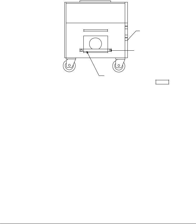
NOTICE: When the range is mounted on casters, it must be installed with the casters supplied, a connector (not supplied by Vulcan-Hart) complying with either ANSI-Z21.69 (latest edition) or CAN/CGA-6.16 (latest edition), and a quick-disconnect device complying with either ANSI-Z21.41 (latest edition) or CAN1-6.9 (latest edition). It must also be installed with restraining means to guard against transmission of strain to the connector, as specified in the appliance manufacturer’s instructions. Attach the restraining device at the rear of the oven (Fig. 1).
Provide a gas line strain relief to limit movement of the range without depending on the connector and/or any quick-disconnect device or its associated piping to limit movement of the range. Attach the gas line strain relief to the rear of the range (Fig. 1).
Should it be necessary to disconnect the restraint, turn off the gas supply before disconnection. Reconnect the restraint before turning the gas supply on and returning the range to its installation position.
CONNECT GAS LINE
STRAIN
RELIEF HERE
PL-51219
Fig. 1
— 7 —
Bumper Bars (Convection Oven Ranges Only)
CAUTION: Failure to install bumper bars may cause motor damage and will void the warranty.
Remove existing #10 screws. Position bumper bars (supplied) as shown. Replace #10 screws and secure bumper bars (Fig. 2).
REAR VIEW OF RANGE
NOTES:
1. Bumper bars required for all Convection Oven Ranges.
2. Restraining device required for all ranges with casters.
3. Restraining device not supplied by unit manufacturer.
RESTRAINING DEVICE
#10 SHEET METAL SCREW
BUMPER BAR
PL-50109
Fig. 2
Installation of Broiler/Griddle Bricks
The Restaurant Range broiler/griddle utilizes ceramic fire bricks for heat radiation of the burners. Install the broiler bricks before connecting the gas supply line.
1.Remove the six 51/4" (133.4 mm) x 21/4" (57 mm) and (6) 51/4" (133.4 mm) x 51/16" (128.6 mm) bricks from the shipping box.
2.Install the six 51/4" (133.4 mm) x 21/4" (57 mm) bricks to the leftand right-hand sides of the burner. To install the bricks, insert them one at a time through the opening in the front of the broiler. Angle the brick sideways so that it will slip between the burner edges. Set the bricks flat in place resting on these edges. Push each brick installed as far to the rear of the burner as possible so that the last brick will install easily (Fig. 3).
3.Install the six 51/4" (133.4 mm) x 51/16" (128.6 mm) bricks to the center burners as described in Step 2.
Installation of Standard Griddle Top Bricks
The griddle top section is extremely heavy. It will require three people to install the griddle and griddle brick — two people to lift the griddle plate and one person to set the bricks and griddle thermostat capillary bulb(s) in place.
— 8 —
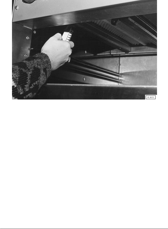
Fig. 3
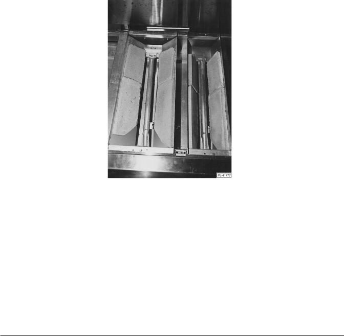
The Restaurant Range griddle top section utilizes a two-fold baffle assembly to support the composite/mortar fire bricks. There will always be only one small 61/2" (165 mm) wide baffle assembly with every griddle top order. There will be at least one 97/8" (251 mm) wide baffle assembly per griddle, possibly more, depending on the griddle width.
The 61/2" (165 mm) wide baffle will utilize two 10" x 4" (254 x 101.6 mm), and two 7" x 4" (177.8 x 101.6 mm) brick sets.
The 97/8" (251 mm) wide baffle assembly will utilize two 10" x 4" (254 x 101.6 mm), and two 7" x 4" (177.8 x 101.6 mm) brick sets.
1.The griddle bricks are shipped in a rectangular cardboard box. Locate the box and carefully inspect quantities as explained above.
NOTE: If a brick has been broken into two pieces, it can still be used. Just place the pieces into position as shown in Fig. 4. However, if a brick is broken into more than two pieces, it will need to be replaced. Contact your local Vulcan servicer.
2.Clean anti-rust coating from top of griddle, following the procedures described in the CLEANING - GRIDDLE PLATE section of this manual.
3.Remove griddle plate. With one person at either side of the griddle, gently lift griddle straight up. DO NOT pull griddle forward until the third person has checked to ensure that the capillary bulb(s) (thermostatically controlled models only) are freed from the underside of the griddle plate. If bulb(s) are still attached to the griddle, pull capillary bulb(s) wire gently through the “V” shields until the bulb(s) are free. Rest the griddle plate in a secure place.
—9 —
4.Exercise caution when placing brick in a thermostatically controlled griddle section. DO NOT hit thermostat bulb while installing bricks. The thermostat bulb is a sensitive device and may be easily knocked out of adjustment.
Into the 61/2" (165 mm) wide baffle, install:
a.Two 10" x 4" (254 x 101.6 mm) bricks, placing the miter edge, one to each side of the front burner baffle area (Fig. 4).
b.Two 7" x 4" (177.8 x 101.6 mm) bricks, one to each side of the rear burner baffle area (Fig. 4).
Fig. 4
5.Into the 97/8" (251 mm) wide baffle, install:
a.Two 10" x 4" (254 x 101.6 mm) bricks, placing the miter edge, one to each side of the front burner baffle area (see Fig. 4).
b.Two 7" x 4" (177.8 x 101.6 mm) bricks, one to each side of the rear burner baffle area (see Fig. 4).
6.If burner has been strapped down, remove the wire strapping device, using wire cutters.
—10 —
 Loading...