


INSTALLATION & OPERATION MANUAL
GAS RESTAURANT RANGES
MODELS
V24
V36
V36F
V60
V60F
V260
www.vulcanhart.com
ITW Food Equipment Group, LLC |
|
An Illinois Tool Works Company |
|
3600 North Point Blvd. |
|
Baltimore, MD 21222 |
F-35692 (10-09) |
IMPORTANT FOR YOUR SAFETY
THIS MANUAL HAS BEEN PREPARED FOR PERSONNEL QUALIFIED TO INSTALL GAS EQUIPMENT, WHO SHOULD PERFORM THE INITIAL FIELD START-UP AND ADJUSTMENTS OF THE EQUIPMENT COVERED BY THIS MANUAL.
POST IN A PROMINENT LOCATION THE INSTRUCTIONS TO BE FOLLOWED IN THE EVENT THE SMELL OF GAS IS DETECTED. THIS INFORMATION CAN BE OBTAINED FROM THE LOCAL GAS SUPPLIER.
IMPORTANT
IN THE EVENT A GAS ODOR IS DETECTED, SHUT
DOWN UNITS AT MAIN SHUTOFF VALVE AND
CONTACT THE LOCAL GAS COMPANY OR GAS
SUPPLIER FOR SERVICE.
FOR YOUR SAFETY
DO NOT STORE OR USE GASOLINE OR OTHER
FLAMMABLE VAPORS OR LIQUIDS IN THE
VICINITY OF THIS OR ANY OTHER APPLIANCE.
WARNING
IMPROPER INSTALLATION, ADJUSTMENT,
ALTERATION, SERVICE OR MAINTENANCE CAN
CAUSE PROPERTY DAMAGE, INJURY OR DEATH.
READ THE INSTALLATION, OPERATING AND
MAINTENANCE INSTRUCTIONS THOROUGHLY
BEFORE INSTALLING OR SERVICING THIS
EQUIPMENT.
IN THE EVENT OF A POWER FAILURE, DO NOT
ATTEMPT TO OPERATE THIS DEVICE.
— 2 —
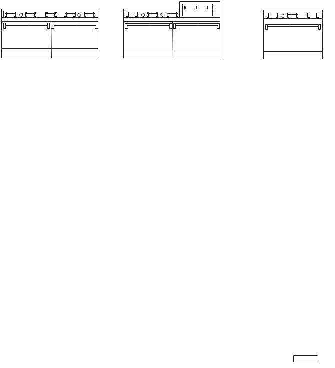
GAS RESTAURANT RANGE MODELS
V60 |
V260 |
V36 |
PL-53007
— 3 —

Installation, Operation and Care of
GAS RESTAURANT RANGES
PLEASE KEEP THIS MANUAL FOR FUTURE REFERENCE
GENERAL
Vulcan ranges and ovens are produced with quality workmanship and material. Proper installation, usage and maintenance of your range will result in many years of satisfactory performance.
Vulcan-Hart suggests that you thoroughly read this entire manual and carefully follow all of the instructions provided.
INSTALLATION
UNCRATING
This range was inspected before leaving the factory. The transportation company assumes full responsibility for safe delivery upon acceptance of the shipment. Immediately after unpacking, check for possible shipping damage. If the range is found to be damaged, save the packaging material and contact the carrier within 15 days of delivery.
Uncrate unit carefully and place in a work-accessible area as near to its final installed position as possible. Remove all shipping wire and wood blocking.
Before installing, check the electrical service (convection oven series ranges only) and type of gas supply (natural or propane) to make sure they agree with the specifications on the rating plate located on the inside of the lower kick panel. If the supply and equipment requirements do not agree, do not proceed with the installation. Contact your dealer or Vulcan-Hart Company immediately.
LOCATION
The equipment area must be kept free and clear of combustible substances.
The range, when installed, must have a minimum clearance from combustible construction of 12" (304 mm) at the sides and 10" (253 mm) at the rear. Clearance from non-combustible construction is 0" at the sides and 6" (152 mm) at the rear.
The installation location must allow adequate clearances for servicing and proper operation. A minimum front clearance of 40" (1016 mm) is required.
The range must be installed so that the flow of combustion and ventilation air will not be obstructed. Adequate clearance for air openings into the combustion chamber must be provided. Make sure there is an adequate supply of air in the room to allow for combustion of the gas at the burners.
— 4 —
INSTALLATION CODES AND STANDARDS
Ranges must be installed in accordance with:
In the United States of America:
1.State and local codes.
2.National Fuel Gas Code, ANSI/Z223.1 (latest edition). Copies may be obtained from The American Gas Association, Inc., 1515 Wilson Blvd., Arlington, VA 22209.
NOTE: In the Commonwealth of Massachusettes,
All gas appliances vented through a ventilation hood or exhaust system equipped with a damper or with a power means shall comply with 248 CMR.
3.National Electrical Code, ANSI/NFPA-70 (latest edition). Copies may be obtained from The National Fire Protection Association, Batterymarch Park, Quincy, MA 02269.
4.Vapor Removal From Cooking Equipment , NFPA-96 (latest edition). Copies may be obtained from The National Fire Protection Association, Batterymarch Park, Quincy, MA 02269.
In Canada:
1.Local codes.
2.CSA B149.1 Natural Gas and Propane Installation Code.
3.CSA C22.1 Canadian Electric Code.
4.CSA C22.2 Canadian Electric Code.
The above are available from the Canadian Standard Association, 5060 Spectrum Way, Suite 100, Mississauga, Ontario, Canada L4W 5N6.
ASSEMBLY
Ranges Mounted on Casters
Ranges mounted on casters must use a flexible connector (not supplied by Vulcan) that complies with the Standard for ConnectorsforMovableGasAppliances,ANSI-Z21.69•CSA6.16 and a quick-disconnect device that complies with the Standard for Quick-Disconnect Devices for Use With Gas
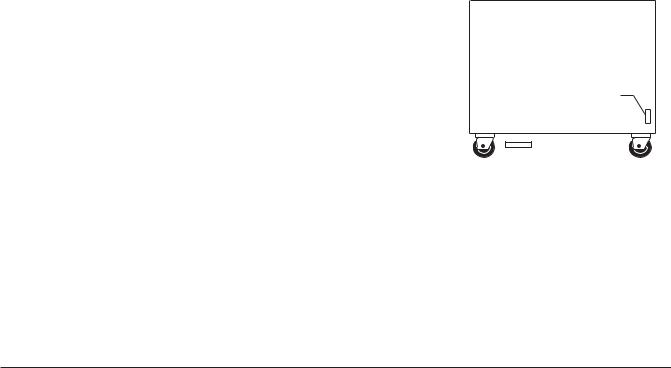
Fuel, ANSI-Z21.41 • CSA 6.9. In addition, adequate means must be provided to limit movement of the appliance without depending on the connector and the quick-disconnect device or its associated piping to limit appliance movement. Attach the restraining device at the rear of the range as shown in Fig. 1.
CONNECT GAS LINE STRAIN
RELIEF HERE
PL-51219
Remove two screws from the rear of the range and install the tie-down strap shipped with the casters using these screws
(Fig. 1). Attach the gas line strain relief to the tie-down strap at the rear of the range (Fig. 1).
If disconnection of the restraint is necessary, turn off the gas supply before disconnection. Reconnect this restraint prior to turning the gas supply on and returning the range to its installation position.
Separate instructions for installing casters to the range are included with the casters.
Note: If the range is installed on casters and is moved for any reason, it is recommended that the range be releveled front to back and side to side.
— 5 —
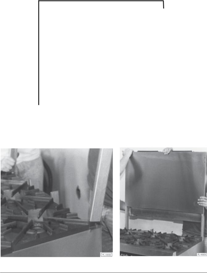
Installation of Broiler/Griddle Bricks
The Restaurant Range broiler/griddle utilizes ceramic fire bricks for heat radiation of the burners. Install the broiler bricks before connecting the gas supply line.
1. Remove the six 5 1/4" x 2 1/4" (133 x 57 mm) and (6) 5 1/4" x 5 1/16" (133 x 128 mm) bricks from the shipping box.
2.Install the six 5 1/4" x 2 1/4" (133 x 57 mm) bricks to the leftand right-hand sides of the burner. To install the bricks, insert them one at a time through the opening in the front of the broiler. Angle the brick sideways so that it will slip between the burner edges. Set the bricks flat in place resting on these edges. Push each brick installed as far to the rear of the burner as possible so that the last brick will install easily (Fig. 3).
3. Install the six 5 1/4" x 5 1/16" (133 x 128 mm) bricks to the center burners as described in Step 2.
Fig. 3
— 6 —
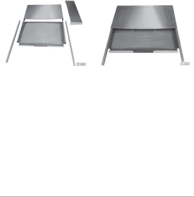
Backsplash
The standard Restaurant Range is equipped with a 23" (584 mm) high backsplash and shelf.
1.Remove the backsplash components from the crating materials.
2.Check the backsplash component parts against the list on page 10 to ensure that all the required parts for the backsplash installation have been obtained. (See Fig’s. 8 & 9.) If any parts are missing, contact your dealer or closest parts depot immediately.
3.Assemble the required components as shown in Fig’s. 8 and 9.
4.Lift the assembly up, sliding the channels into the space provided at the rear of the range (this may require two people).
F ig. 8 |
F ig. 9 |
— 7 —
Backsplash Component Parts
MODELS
W36 |
W60 |
|
W260 |
|
|
|
|
||
Std. 23" (584 mm) High |
Std. 23" (584 mm) High |
Std. 23" (584 mm) High |
||
Backsplash (1) |
Backsplash |
(1) |
Backsplash |
(1) |
|
|
|
||
Backsplash Channel |
Backsplash Channel |
Backsplash Channel |
||
(2) |
(1) |
|
(2) |
|
|
|
|
|
|
Heat Shield (1) |
Heat Shield (1) |
|
Heat Shield (1) |
|
|
|
|
|
|
#10 Sht.Metal Screw |
#10 Sht. Metal Screw |
|
#10 Sht. Metal Screw |
|
(4) |
(8) |
|
(8) |
|
|
|
|
||
1/4-20 x 2 5/16" (59 mm) Lg. |
1/4-20 x 2 5/16" (59 mm) Lg. |
1/4-20 x 2 5/16" (59 mm) Lg. |
||
Machine Screw (4) |
Machine Screw (4) |
Machine Screw (4) |
||
|
|
|
|
|
Shelf Assembly (1) |
Shelf Assembly |
(1) |
Shelf Assembly |
(1) |
|
|
|
|
|
5.It may be necessary to pull the heat shield bottom out slightly in order to clear the oven flue box area. Be sure the backsplash is resting evenly and the channel holes are lining up with the holes provided in the rightand left-hand body side (Fig’s. 10 & 11).
F ig. 10 |
F ig. 11 |
— 8 —
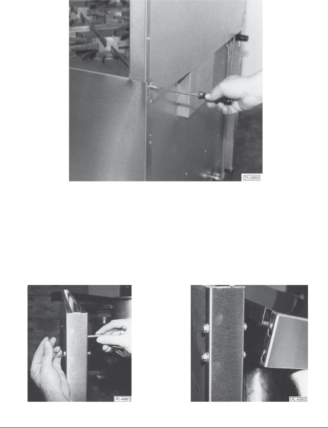
6. Install four #10 sheet metal screws (2 to each channel leg) (Fig. 12).
Fig. 12
7. From the front, install four 1/4-20 x 2 5/16 " (59 mm) long machine screws and secure bolts with
locknuts. Do not tighten the screws all the way down. Leave about |
1/4" (6 mm) of play in each screw |
(Fig. 13). |
|
8.Lift the shelf up and slide the shelf into position over the screw heads (Fig. 14).
9.Tighten the four screws to secure the shelf.
F ig. 13 |
F ig. 14 |
— 9 —

LEVELING
Check the leveling of the range. Place a carpenter’s level inside the oven cavity across the oven rack(s). Level front-to-back and side-to-side.
To adjust the leveling, tilt the range to one side and, using channel locks, unscrew the adjustable leg insert as required. Repeat this procedure as necessary for each leg.
Casters for this range are of the non-adjustable type. Therefore, the floor must be level. If floor surface is not level, the range will experience cooking problems.
GAS CONNECTIONS
CAUTION: All gas supply connections and any pipe joint compound used must be resistant to the action of propane gases.
Each range is factory-equipped for the type gas specified on the rating plate. The installation gas connection is a 3/4" (19 mm) 14 FPT ANSI schedule #40 standard pipe.
Connect gas supply. Make sure the pipes are clean and free of obstructions.
Codes require that a gas shutoff valve be installed in the gas line ahead of the range.
Standard ranges are equipped with fixed burner orifices which coincide with installation elevation.
Install the gas pressure regulator.
Before installing, ensure that regulator supplied agrees with rating plate gas supply.
As of 7/11/90, the gas pressure regulator is NOT factory installed. The regulator for this gas type is sealed within a plastic bag attached to the oven rack inside the oven cavity. This regulator must be field installed by a qualified installer.
Natural gas regulators are preset for 4" W.C. (Water Column) (.99 kPa); propane gas regulators for 10.0" W.C. (2.5 kPa)
1.Locate 3/4" (19 mm) gas connection pipe extending from rear of range.
2.Cover pipe threads with leak sealant.
3.Screw regulator hand-tight onto pipe with regulator arrow pointing towards range body back (Fig. 15).
4.Using pipe wrench, tighten regulator securely in an upright position (Fig. 15).
The arrow on the regulator shows the direction of the gas flow (Fig. 15). The pressure regulator must be mounted horizontally to ensure proper preset outlet pressure. If the regulator is installed in any other position, the outlet pressure must be reset for proper operation.
A leak limiter is supplied with every regulator to allow excess gas pressure to escape. Do not obstruct leak limiter on gas pressure regulator, as obstruction may cause regulator to malfunction.
— 10 —
Fig. 15
WARNING: PRIOR TO LIGHTING, CHECK ALL JOINTS IN THE GAS SUPPLY LINE FOR LEAKS. USE SOAP AND WATER SOLUTION. DO NOT USE AN OPEN FLAME.
After piping has been checked for leaks, all piping receiving gas should be fully purged to remove air.
Before operation, verify thermocouple is securely seated in the safety valve. The thermocouple should be tightened a 1/4 turn past finger tight. DO NOT OVERTIGHTEN. Overtightening may damage the thermocouple or safety magnet.
TESTING THE GAS SUPPLY SYSTEM
When gas supply pressure exceeds 1/2 psig (3.45 kPa), the range and its individual shutoff valve must be disconnected from the gas supply piping system.
When gas supply pressure is 1/2 psig (3.45 kPa) or less, the range should be isolated from the gas supply system by closing its individual manual shutoff valve until the range is ready for start-up.
FLUE CONNECTIONS
DO NOT obstruct the flow of flue gases from the flue located on the rear of the range. It is recommended that the flue gases be ventilated to the outside of the building through a ventilation system installed by qualified personnel.
From the termination of the flue to the filters of the hood venting system, a minimum clearance of 18" (457 mm) must be maintained.
Information on the construction and installation of ventilating hoods may be obtained from the standard for the "Removal of Vapors from Commercial Cooking Equipment”, NFPA No. 96 (latest edition), available from The National Fire Protection Association, Batterymarch Park, Quincy, MA 02269.
— 11 —

OPERATION
WARNING: THE RANGE AND ITS PARTS ARE HOT. BE VERY CAREFUL WHEN OPERATING, CLEANING OR SERVICING THE RANGE.
CONTROLS
THERMOSTAT DIAL - STANDARD OVEN |
— Allows operator to regulate oven temperature from low to |
|
500°F (260°C). |
GRIDDLE BURNER KNOB - |
|
STANDARD AND CONVECTION OVENS |
— Regulates gas flow to the griddle or hot top burner. To |
|
increase heat, turn knob counterclockwise; to decrease, |
|
turn knob clockwise. |
BEFORE FIRST USE
Griddle Seasoning
CAUTION: This griddle plate is steel, but the surface is relatively soft and can be scored or dented by the careless use of a spatula or scraper. Be careful not to dent, scratch, or gouge the plate surface. Do not try to knock off loose food that may be on the spatula by tapping the corner edge of the spatula on the griddle surface.
A new griddle surface must be seasoned to do a good cooking job. The metal surface of the griddle is porous. Food tends to get trapped in these pores and stick; therefore, it is important to “season” or “fill up” these pores with cooking oil before cooking. Seasoning gives the surface a slick, hard finish from which the food will release easily.
To season, heat griddle top section at a low burner setting. Pour one ounce of cooking oil per square foot of surface over the griddle top section. With an insulated cloth, spread the oil over the entire griddle surface to create a thin film. Wipe off any excess oil with an insulated cloth.
Repeat this procedure 2 to 3 times until the griddle has a slick surface.
— 12 —
LIGHTING AND SHUTTING DOWN PILOTS
All adjustment procedures associated with pilot lighting must be performed by an authorized Vulcan-Hart installation or service person.
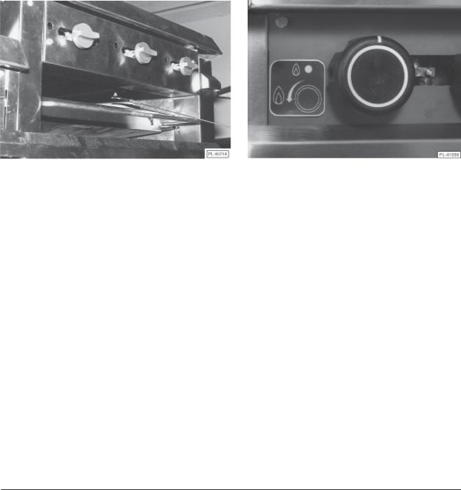
HOT TOP AND GRIDDLE TOP BURNERS
1.Turn main gas supply ON.
2.Wait 30 seconds and, using a taper, light the hot top or griddle top pilot (Fig. 16).
S hown with old s tyle burner knobs |
New s tyle burner knobs effective 1/98 |
Fig. 16
3.If pilot fails to light, turn main gas supply OFF. Wait 5 minutes and repeat the above procedures.
4.Turn one hot top or griddle top burner valve ON to remove air from the gas line. Turn burner valve OFF when gas begins to flow.
Nightly Shutdown
Turn burner valve OFF; pilot will remain lit.
Complete Shutdown
1.Turn burner valve OFF; pilot will remain lit.
2.Turn main gas supply OFF.
— 13 —
OPEN TOP BURNERS
1.Turn main gas supply ON.
2.Wait 30 seconds and, using a taper, light the open top pilot (Fig. 17).
Fig. 17
3.If pilot fails to light, turn main gas supply OFF. Wait 5 minutes and repeat the above procedures.
4.Turn one open top burner valve ON to remove air from the gas line. Turn burner OFF when gas begins to flow.
Nightly Shutdown
Turn burner valve OFF; pilot will remain lit.
Complete Shutdown
1.Turn burner valve OFF; pilot will remain lit.
2.Turn main gas supply OFF.
BROILER/GRIDDLE
1. Turn main gas supply ON.
2Wait 30 seconds and, using a taper, light broiler/griddle pilot (see Fig. 16).
3.If pilot fails to light, turn main gas supply OFF. Wait 5 minutes and repeat Steps 1 and 2.
4.Turn burner valve ON to purge air from the lines. Turn burner valve OFF when gas begins to flow.
Nightly Shutdown
Turn burner valve OFF; pilot will remain lit.
Complete Shutdown
1.Turn burner valve OFF; pilot will remain lit.
2.Turn main gas supply OFF.
— 14 —
STANDARD OVEN LIGHTING AND SHUTDOWN INSTRUCTIONS
NOTE: Light open top/griddle pilots before lighting oven pilot.
1.Turn thermostat to the “OFF” POSITION.
2.Wait 5 Minutes.
3.After pilot is lit, turn the thermostat to the desired setting.
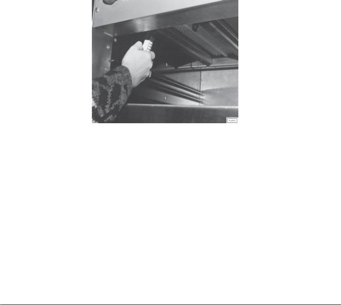
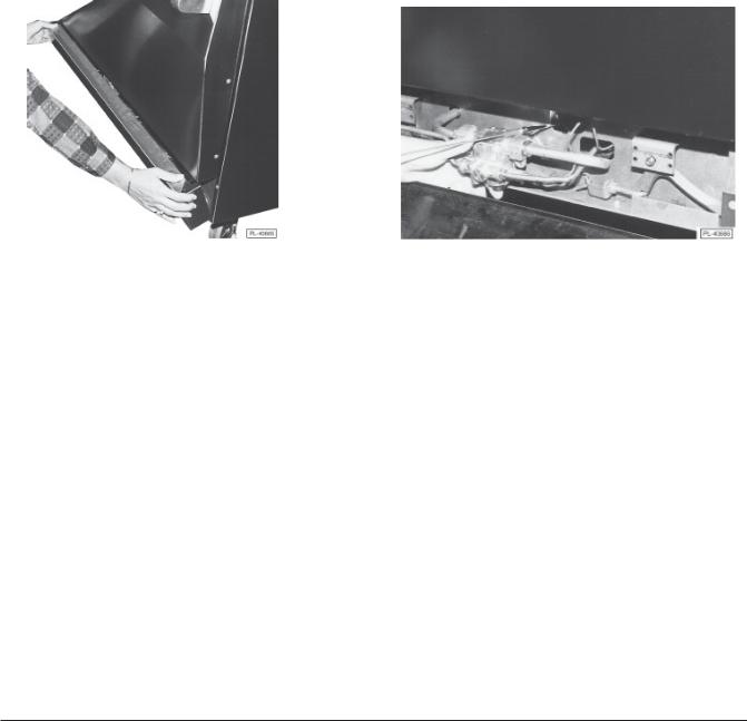
4.Remove the lover panel. (Fig. 18)
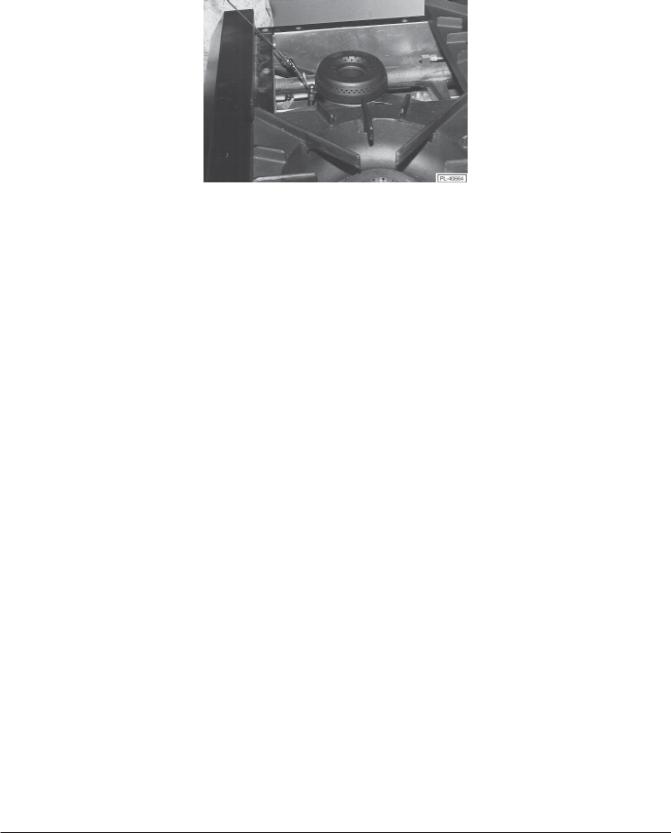
5.Depress the red button on the safety valve and light the pilot through the observation area. (Fig. 19)
6.Hold down the red button for atleast 30 seconds.
7.When button is released, pilot should remain lit.
8.Replace lower panel.
9.Turn thermostat to desired temperature.
10.If the pilot becomes extinguished repeat the above procedure.
F ig. 18 |
F ig. 19 |
Nightly Shutdown
Turn oven thermostat OFF.
Complete Shutdown
1.Turn oven thermostat OFF.
2.Turn main gas supply OFF.
RACK ARRANGEMENT - STANDARD OVEN
The standard oven has two rack positions and is supplied with one oven rack. Additional racks may be obtained through a Vulcan-Hart parts depot.
For best results when baking cakes and pastries, it is recommended that only a single rack position be utilized. However, proper rack usage and positioning is really determined by the individual cooking needs of the operator. If you are cooking a large roast, the entire oven cavity may be utilized. Remove the oven rack completely from the range and place the roasting pan directly on the oven bottom.
— 15 —
STANDARD OVEN
Light open top/griddle pilots before lighting oven pilot.
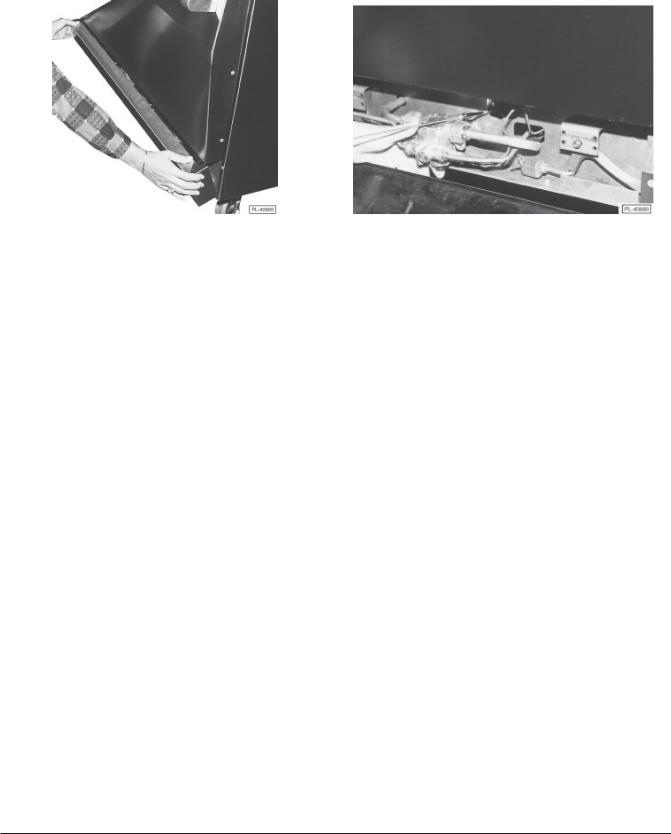
1. Open kick panel and lift up the pilot lighting hole cover (Fig. 18).
F ig. 18 |
F ig. 19 |
2.Light pilot by depressing the reset button located behind the kick panel (Fig. 19). Continue to hold reset button in for 1 minute. If pilot fails to light, turn main gas supply OFF and wait 5 minutes before repeating Step 2.
3.After pilot is lit, turn the thermostat to the desired setting.
Nightly Shutdown
Turn oven thermostat OFF.
Complete Shutdown
1.Turn oven thermostat OFF.
2.Turn main gas supply OFF.
RACK ARRANGEMENT - STANDARD OVEN
The standard oven has four rack positions and is supplied with one oven rack. Additional racks may be obtained through a Vulcan-Hart parts depot.
For best results when baking cakes and pastries, it is recommended that only a single rack position be utilized. However, proper rack usage and positioning is really determined by the individual cooking needs of the operator. If you are cooking a large roast, the entire oven cavity may be utilized. Remove the oven rack completely from the range and place the roasting pan directly on the oven bottom.
— 16 —

INSERTING AND REMOVING STANDARD
The oven rack has a stop to keep the rack from being pulled all the way out when unloading product. To install rack, place rack along side of top of side liner runners and slide rack completely to the rear of the oven compartment until rack drops into place (Fig’s. 24 & 25).
F ig. 24 |
F ig. 25 |
To remove rack, reverse the procedure above by raising rear of oven rack stop above runner and pulling rack forward (Fig. 26).
Fig. 26
— 17 —
 Loading...