


FK
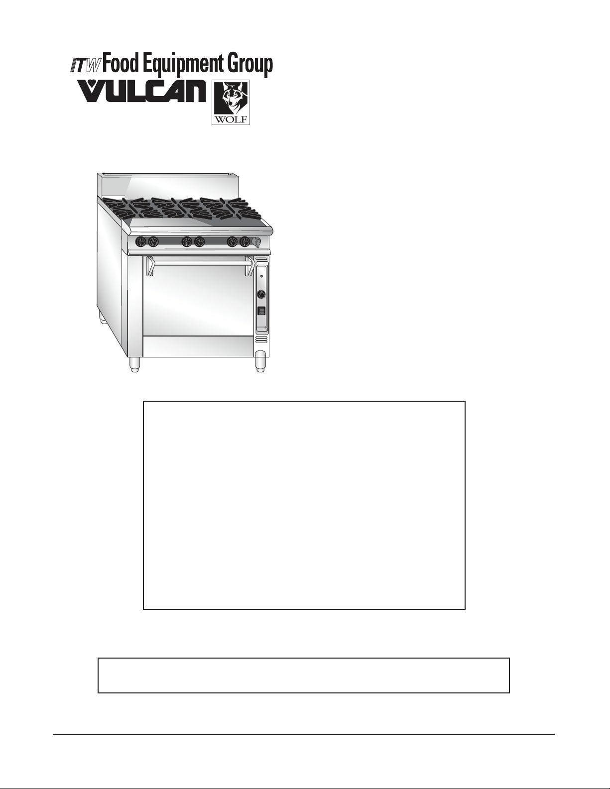
ONE POWERFUL PACKAGE
OPERATIONS MANUAL
COMMANDER SERIES
GAS RANGE
MODEL
FK Series Convection Oven
FV Series Standard Oven
FB Series Cabinet Base
FM Series Modular Unit
FK36_A Convection Oven
- NOTICE -
This manual is prepared for use by trained service technicians
and should not be used by those not properly qualied.
If you have attended a service school for this product, you may
still be qualied to perform the procedures described in this
manual.
This manual is not intended to be all encompassing. If you have
not attended a service school for this product, you should read,
in its entirety, the repair procedure you wish to perform to
determine if you have the necessary tools, instruments and skills
required to perform the procedure. Procedures for which you do
not have the necessary tools, instruments and skills should be
performed by a trained service technician.
DESCRIPTION
Reproduction or other use of this manual, without the express
written consent of Vulcan-Hart/Wolf, is prohibited.
For additional information on Vulcan-Hart/Wolf or to locate an authorized parts and service
provider in your area, visit our website at www.vulcanhart.com or www.wolfrange.com.
VULCAN-HART/WOLF
DIVISION OF ITW FOOD EQUIPMENT GROUP, LLC
WWW.VULCANHART.COM / WWW.WOLFRANGE.COM
3600 NORTH POINT BLVD.
BALTIMORE, MD 21222
F-35683 (02-2007)
IMPORTANT FOR YOUR SAFETY
THIS MANUAL HAS BEEN PREPARED FOR PERSONNEL QUALIFIED TO INSTALL GAS
EQUIPM ENT , WHO SH OULD PERFOR M THE IN ITIAL FIELD START-UP AND
ADJUSTMENTS OF THE EQUIPMENT COVERED BY THIS MANUAL.
POST IN A PROMINENT LOCATION THE INSTRUCTIONS TO BE FOLLOWED IN THE
EVENT THE SMELL OF GAS IS DETECTED. THIS INFORMATION CAN BE OBTAINED
FROM THE LOCAL GAS SUPPLIER.
IMPORTANT
IN THE EVENT A GAS ODOR IS DETECTED, SHUT
DOWN UNITS AT MAIN SHUTOFF VALVE AND
CONTACT THE LOCAL GAS COMPANY OR GAS
SUPPLIER FOR SERVICE.
FOR YOUR SAFETY
DO NOT STORE OR USE GASOLINE OR OTHER
FLAMMABLE VAPORS OR LIQUIDS IN THE
VICINITY OF THIS OR ANY OTHER APPLIANCE.
WARNING
IMP ROP ER IN STA LLA TION, A DJU STMENT,
ALTERATION OR MODIFICATION, SERVICE OR
MA INT ENA NCE CA N CA USE PROPE RTY
DAMAGE , INJ URY O R DEA TH. REA D THE
INSTALLATION, OPERATING AND MAINTENANCE
IN STR UCT ION S TH ORO UGH LY BEFO RE
INSTALLING OR SERVICING THIS EQUIPMENT.
IN THE EVENT OF A POWER FAILURE, DO NOT
ATTEMPT TO OPERATE THIS DEVICE.
— 2 —
— 3 —
Installation, Operation and Care Of
HEAVY DUTY SECTIONAL GAS RANGES
PLEASE KEEP THIS MANUAL FOR FUTURE REFERENCE
GENERAL
Heavy duty sectional ranges are produced with quality workmanship and material. Proper installation,
usage and maintenance of your range will result in many years of satisfactory performance.
The manufacturer suggests that you thoroughly read this entire manual and carefully follow all of the
instructions provided.
INSTALLATION
UNPACKING
This range was inspected before leaving the factory. The transportation company assumes full
responsibility for safe delivery upon acceptance of the shipment. Immediately after unpacking, check
for possible shipping damage. If the range is found to be damaged, save the packaging material and
contact the carrier within 15 days of delivery.
Carefully unpack range(s) and place in the approximate installation position, whether as a battery or
single stand-alone range.
Remove parts (packed in a cardboard box) from oven cavity, or cabinet body, or on top of modular
range(s).
Remove wire or nut from rear of each burner before installing the range.
Before installing, check the electrical service (Convection Oven Models only) and type of gas supply
(natural or propane) to make sure they agree with the specications on the rating plate located on the
inside of the burner box lower panel. The rating plate will show the voltage, phase, cycle, full load
ampere, BTU, as well as the type of gas. If the supply and equipment requirements do not agree, do
not proceed with the installation. Contact your dealer or manufacturer.
LOCATION
CAUTION: The equipment area must be kept free and clear of combustible substances.
The minimum installation clearances from combustible and noncombustible construction for ranges
using inputs of 30,000 BTU/Hr. per open top burner are:
Combustible Noncombustible
Sides 20" (508 mm) 0"
Rear 2" (51 mm) 0"
— 4 —
The minimum installation clearances from combustible and noncombustible construction for ranges
using inputs of 20,000 Btu/Hr per open top burner are:
Combustible Noncombustible
Sides 6" (152 mm) 0"
Rear 2" (51 mm) 0"
The ranges are suitable for installation on combustible oors when 6" (152 mm) adjustable legs are
used. When legs are removed, use only on noncombustible oors, curb, or platform, with front
appliance projecting 3" (76 mm) beyond curb or platform.
Ranges with convection ovens should be installed on 6" (152 mm) legs or casters, allowing 6" (152 mm)
clearance from the rear of the range. If ranges with convection ovens are installed directly on curbs,
without legs, or in back-to-back installations, provisions must be made for adequate air circulation, and
these provisions must be approved by the manufacturer's Service Department. Contact the Service
Department at the address or phone number shown on the front cover of this manual.
All modular ranges are to be installed only on non-combustible oors.
The installation location must allow adequate clearances for servicing and proper operation. A
minimum front clearance of 35" (889 mm) is required.
The range(s) must be installed so that the ow of combustion and ventilation air will not be obstructed.
Adequate clearance for air openings into the combustion chamber(s) must be provided. Make sure
there is an adequate supply of air in the room to allow for combustion of the gas at the burners.
INSTALLATION CODES AND STANDARDS
Your range(s) must be installed in accordance with:
In the United States:
1. State and local codes.
2. National Fuel Gas Code, ANSI/Z223.1/NFPA #54 (latest edition). Copies may be obtained
from The American Gas Association, Accredited Standards Committee Z223 @ 400 N.
Capital St. NW, Washington, DC 2001 or the Secretary Standards Council, NFPA,
1 Batterymarch Park, Quincy, MA 02169-7471.
NOTE: In the Commonwealth of Massachusetts, All gas appliances vented through a
ventilation hood or exhaust system equipped with a damper or with a power means of
exhaust shall comply with 248 CMR.
3. Vapor Removal From Cooking Equipment, NFPA #96 (latest edition). Copies may be
obtained from The National Fire Protection Association, Batterymarch Park, Quincy MA
02169-7471.
4. National Electrical Code, ANSI/NFPA-70 (latest edition). Copies may be obtained from
The National Fire Protection Association, Batterymarch Park, Quincy, MA 02169-7471.
In Canada:
1. Local codes.
2. CSA B149.1 Natural Gas and Propane Installation Code.
3. CSA C22.1 Canadian Electrical Code (latest edition).
The above are available from The Canadian Standard Association, 5060 Spectrum Way, Suite 100,
Mississauga, Ontario, Canada L4W 5N6.
— 5 —
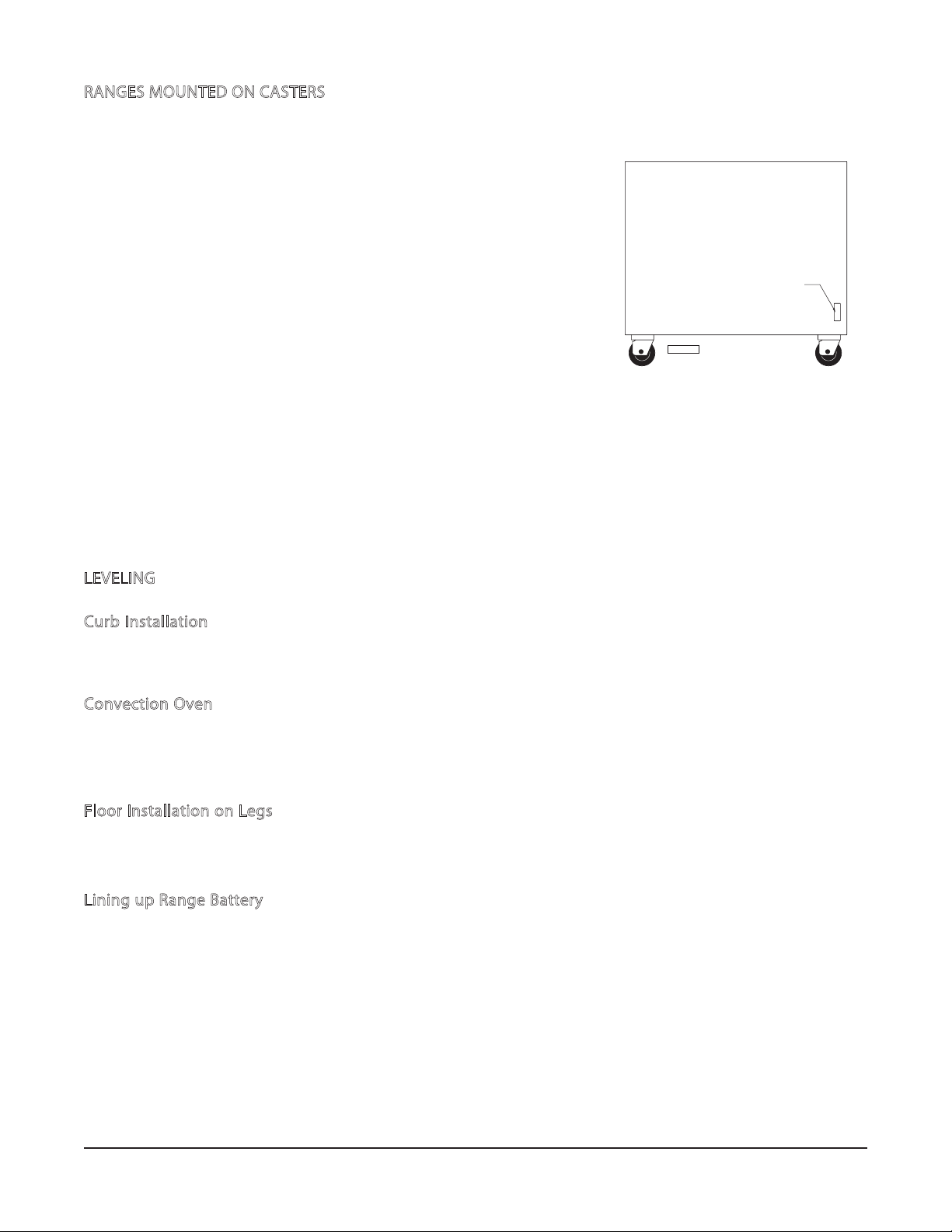
RANGES MOUNTED ON CASTERS
Ranges mounted on casters must use a exible connector
(not supplied by manufacturer) that complies with the
Standard for Connectors for Movable Gas Appliances,
ANSI Z21.69 • CSA 6.16 and a quick-disconnect device
that complies with the Standard for Quick-Disconnect
Devices for Use With Gas Fuel, ANSI-Z21.41 • CSA 6.9. In
add i tion, adequate means mus t be provided to limi t
movement of the appliance without depending on the
connector and the quick-disconnect device or its associated
piping to limit appliance movement. Attach the restraining
CONNEC T GAS LI NE
STRAIN
RELIEF H ERE
device at the rear of the range as shown in Fig. 1.
PL-5121 9
If disconnection of the restraint is necessary, turn o the gas
supply before disconnection. Reconnect this restraint prior to
Fig. 1
turning the gas supply on and returning the range to its
installation position.
Separate instructions for installing casters to the range are included with the casters.
Note: If the range is installed on casters and is moved for any reason, it is recommended that the range
be releveled front to back and side to side.
LEVELING
Curb Installation
Ranges must overhang curb 3" (76 mm) in front. To level each range, remove oven bottom. Adjust
four corner leveling bolts as required to level the appliance on all sides.
Convection Oven
Remove lower front kick plate. Remove two screws holding electric gas valve and move valve o to
the side. Pull oven burner out of compartment through opening. Adjust four corner bolts to level range.
Replace burner valve and kick plate.
Floor Installation on Legs
The 6" (152 mm) adjustable legs must be tightened securely. Level each range by turning the foot
portion of the adjustable legs.
Lining up Range Battery
In batteries of ranges, it is recommended that the center range be installed and leveled rst. Level each
range, one at a time, to line up high shelf and roll front with adjacent range. Bolt the high shelves and
roll fronts together.
— 6 —
CONNECTION OF MANIFOLDS IN BATTERY
Two or more ranges can be coupled together at the manifold by removing the front control panel to
make necessary connections. Be sure to cap open ends. To connect:
1. Adjust manifold by loosening U-bolts. In a large battery of eight or more ranges, gas should
be fed from both ends of the battery. "T" gas connections can be installed whenever necessary
for increased gas supply. For further details, consult your gas company. The top roll front may
also be removed for your convenience.
2. Bolt risers together at top rear.
3. If risers have high shelves, bolt the high shelf brackets together. Replace the high shelves.
4. Use clamp to pull ranges together at the rear. (There is a slotted hole in the top frame side at
5
the rear that can be used to bolt ranges together if necessary. Run a
/16" (8 mm) diameter drill
through the slotted hole, drilling from inside out on each range.) Use 1/4" (6 mm)-2 x 2" (51 mm)
bolt that is provided.
5. Replace all top sections. Make manifold union connections at the front. Do not allow manifold
pipe to turn.
1
6. Bolt the roll front ends together at the front. (Make sure roll fronts match.) Use
/4" (6 mm)-20
x 1" (25 mm) bolts provided.
7. Tighten the front roll front bolts after the roll front ends have been properly bolted together.
8. Before replacing manifold panels, check all gas connections for leaks. (See GAS
CONNECTIONS in this manual.)
If appliance has rear gas connection, carefully check for open gas lines.
The gas pressure regulator must have proper outlet pressure capacity for this battery application.
INSTALLING OVERLAPPING GRIDDLE TOP
1. Bolt ranges together and level per instructions in this manual.
2. Remove chrome bull noses from ranges receiving overlapping griddle tops. Bull noses are held
by bolts on the bottom side.
3. MANUAL CONTROLS ONLY — Set griddle tops in place and level with bolts located under the
griddle top in both rear corners. Should you desire griddle plate to slope forward, adjust
accordingly. Make sure hole in front gutter ts into drain in range. Reinstall bull noses.
4. THERMOSTAT CONTROL ONLY — Set griddle top in place and support front with 4" to 6" (102
to 152 mm) blocks. Insert thermostat probe into smaller of two angles on bottom of griddle top
(bend probe slightly while inserting to hold in place). Slide insulation sleeving around probe
lead up to angle on griddle top. Coil excess lead near thermostat, leaving as little as possible
in burner area. Make sure that thermostat probe lead is not over burner or pilot ame. Remove
supporting blocks and lower griddle top in place.
Level griddle top with bolts located under both rear corners. Should you desire griddle plate
to slope forward, adjust accordingly. Make sure hole in front gutter ts into drain in range.
Reinstall bull noses.
Leveling bolts are provided under each griddle plate at the rear, should you desire griddle plate to slope
forward. Top frame sealing channels are supplied to seal o any space between two or more ranges.
— 7 —
GAS CONNECTIONS
CAUTION: All gas supply connections and any pipe joint compound used must be resistant
to the action of propane gases.
This appliance must be connected with a gas supply line as large or larger ID (net inside diameter) than
the gas pipe inlet provided on the rear of the appliance. Connect gas supply to the range(s). Make sure
the pipes are clean and free of obstructions, dirt, and piping compound.
Codes require that a gas shuto valve be installed in the gas line ahead of the range(s).
Ranges manufactured for use with propane gas are equipped with xed orices.
A gas pressure regulator must be furnished by the installer or plumber at the time of installation. The
regulator must be listed by a nationally recognized testing agency. These appliances are rated at the
following pressure: Natural Gas - 5" W.C. (Water Column) (1.25 kPa); Propane Gas - 10" W.C.
(2.49 kPa).
WARNING: PRIOR TO LIGHTING, CHECK ALL JOINTS IN THE GAS SUPPLY LINE FOR LEAKS
USE SOAP AND WATER SOLUTION. DO NOT USE AN OPEN FLAME.
A. CHECK ALL JOINTS PRIOR TO THE GAS VALVE (SOLENOID) BEFORE LIGHTING UNIT.
B. CHECK ALL JOINTS BEYOND GAS VALVE (SOLENOID) AFTER UNIT IS LIT.
After piping has been checked for leaks, all piping receiving gas should be fully purged to remove air.
TESTING THE GAS SUPPLY SYSTEM
1
When test pressures exceed
/2 psig (3.45 kPa), the range and its individual shuto valve must be
disconnected from the gas supply piping system.
1
When test pressures are
/2 psig (3.45 kPa) or less, the range must be isolated from the gas supply
system by closing its individual manual shuto valve.
FLUE CONNECTIONS
DO NOT obstruct the ow of ue gases from the ue duct located on the rear of the range. It is
recommended that the ue gases be ventilated to the outside of the building through a ventilation
system installed by qualied personnel.
A minimum of 18" (457 mm) must be maintained between the ventilation system and the cooking
surface.
Information on the construction and installation of ventilating hoods may be obtained from the standard
for "
Vapor Removal from Cooking Equipment
," NFPA No. 96 (latest edition), available from the
National Fire Protection Association, Batterymarch Park, Quincy, MA 02169-7471.
— 8 —
ELECTRICAL CONNECTIONS
WARNING: ELECTRICAL AND GROUNDING CONNECTIONS MUST COMPLY WITH THE
APPLICABLE PORTIONS OF THE NATIONAL ELECTRICAL CODE AND/OR OTHER LOCAL
ELECTRICAL CODES.
WARNING: DISCONNECT THE ELECTRICAL POWER TO THE MACHINE AND FOLLOW
LOCKOUT / TAGOUT PROCEDURES.
WARNING: APPLIANCES EQUIPPED WITH A FLEXIBLE ELECTRIC SUPPLY CORD ARE
PROVIDED WITH A THREE-PRONG GROUNDING PLUG. IT IS IMPERATIVE THAT THIS
PLUG BE CONNECTED INTO A PROPERLY GROUNDED THREE-PRONG RECEPTACLE. IF
THE RECEPTACLE IS NOT THE PROPER GROUNDING TYPE, CONTACT AN ELECTRICIAN.
DO NOT REMOVE THE GROUNDING PRONG FROM THIS PLUG.
Do not connect the range to electrical supply until after gas connections have been made.
LIGHTING AND SHUTTING DOWN PILOTS
Open Top, Griddle Top, and Hot Top
1. Turn the main burner valve to the ON position.
2. Turn all burner valves to the OFF position. Wait 5 minutes.
3. If pilot fails to light, repeat steps 1-2 above.
4. For a complete shutdown, turn all burner valves to the OFF position.
Turn gas shut-o valve OFF.
— 9 —
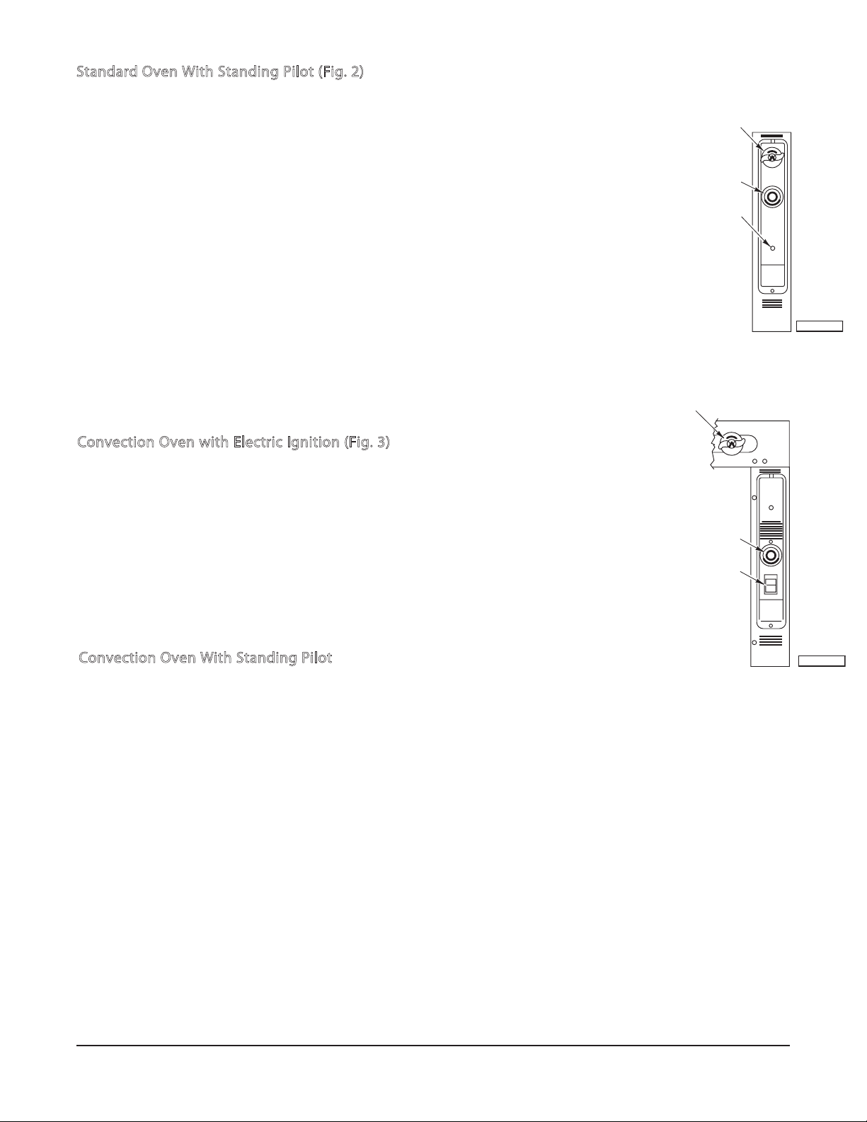
Standard Oven With Standing Pilot (Fig. 2)
1. Turn Thermostat and Shut-Off Valve to the OFF position.
2. Wait 5 minutes.
3. Remove lower panel.
4. Depress Red Button on Safety Valve and light Pilot through observation
hole.
5. Hold down Red Button for at least 30 seconds.
6. When Red Button is released, Pilot should remain lit. Pilot flame may be
adjusted with screw on Pilot Adjustment Valve on Pilot supply tubing located
behind Control Panel. There should be only a slight amount of yellow in the
properly adjusted pilot flame.
7. Replace lower panel.
8. Turn Shut-Off Valve to the ON position and turn the Thermostat to the desired
temperature.
9. If pilot flame becomes extinguished, repeat above procedure.
10. For a complete shutdown, turn the Thermostat, Shut-Off Valve, and gas
shut-off valve to the OFF position.
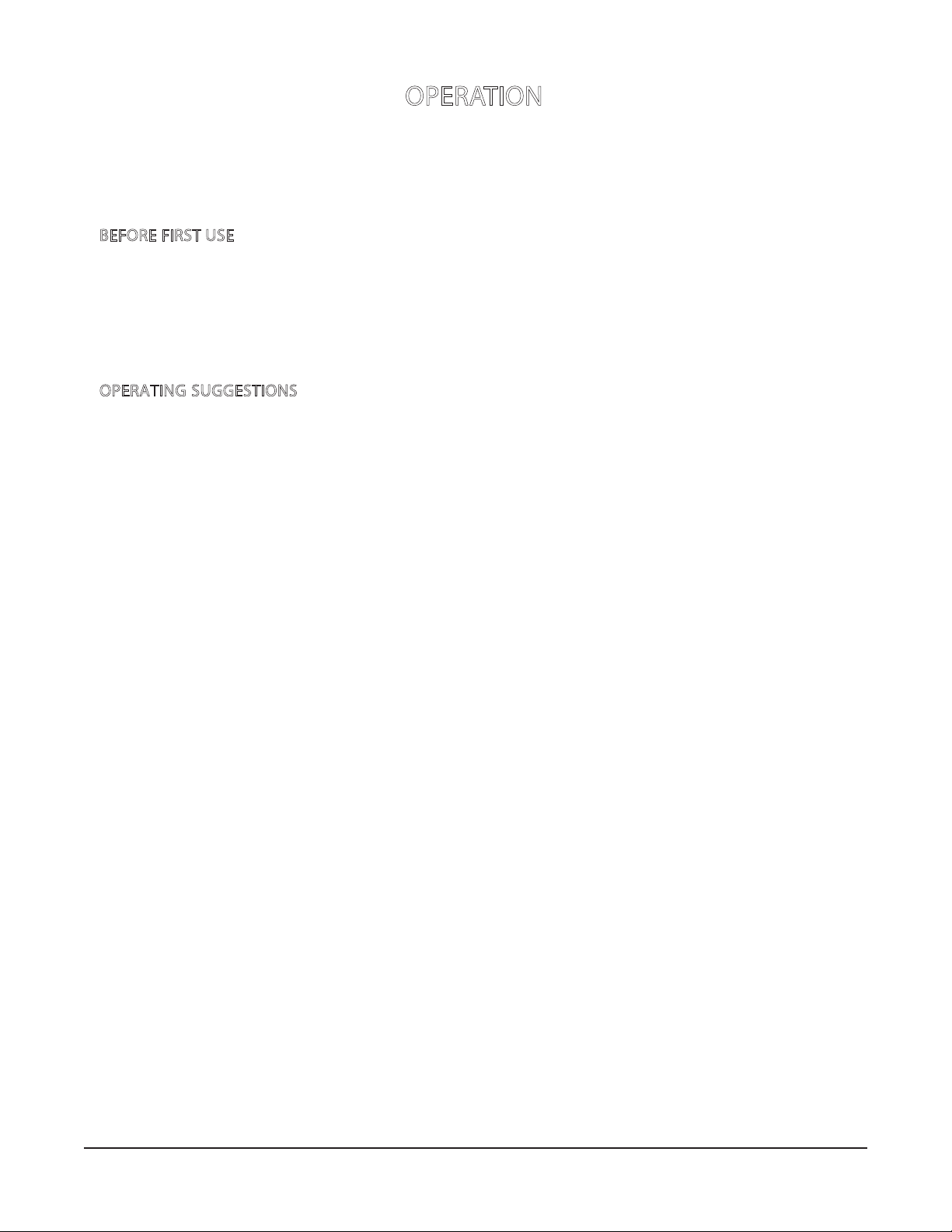
Convection Oven with Electric Ignition (Fig. 3)
1. Turn Thermostat and Shut-Off Valve to the OFF position.
2. Wait 5 minutes.
3. Turn Shut-Off Valve to ON position.
4. Turn Fan Switch to ON position.
5. Turn Thermostat to desired setting.
6. Oven burner lights automatically.
7. For a complete shutdown, turn Thermostat, Fan Switch, Shut-Off Valve,
and gas shut-off valve to the OFF position.
THERMOSTAT
RED BUTTON
SHUT-OFF
VALVE
THERMOSTAT
FAN SWITCH
SHUT-OFF
VALVE
(SAFETY)
PL-53 512
Fig. 2
FAN
Convection Oven With Standing Pilot
1. Turn Thermostat, Shut-O Valve, and Fan Switch to the OFF position.
2. Wait 5 minutes.
3. Remove lower panel.
4. Depress Red Button on Safety Valve and light Pilot through observation
hole.
5. Hold down Red Button for at least 30 seconds.
6. When Red Button is released, Pilot should remain lit. Pilot flame may be
adjusted with screw on Pilot Adjustment Valve on Pilot supply tubing located
behind Control Panel. There should be only a slight amount of yellow in the
properly adjusted pilot flame.
7. Replace lower panel.
8. Turn the Shut-Off Valve and Fan Switch to the ON position and turn the Thermostat
to the desired temperature.
9. If pilot flame becomes extinguished, repeat above procedure.
10. For a complete shutdown, turn the Thermostat, Shut-Off Valve, and gas shut-off
valve to the OFF position.
— 10 —
PL-53 515
Fig. 3
OPERATION
WARNING: THE APPLIANCE AND ITS PARTS ARE HOT. USE CARE WHEN OPERATING,
CLEANING OR SERVICING THE APPLIANCE.
BEFORE FIRST USE
Griddle Tops: Before using your griddle, the protective coating that was applied at the factory must
be completely removed with a commercial degreaser. After a thorough cleaning, apply a
high temperature, salt-free frying oil and you are ready to use the griddle.
The griddle requires no “breaking-in” or “seasoning”.
OPERATING SUGGESTIONS
Standard Oven: If you have a standard oven, use your normal recipe times and temperatures.
Convection Oven: The convection oven does everything a regular oven can do, but with less energy
consumption. The oven pre-heats faster, and baking time, temperature settings, and
shrinkage are reduced.
In general, reduce temperature 25°F (10°C) from conventional recipes.
• Bakery Products: Reduce temperature 25°F (10°C). Reduce time by 25%.
• Casserole Cookery: Reduce temperature about 25°F, and time by 25%.
• Meat Roasting: Reduce temperature to 275-300°F (135-149°C). Use meat thermometer.
Cooking time may be reduced up to 25%.
Use fan for preheating and baking.
Place open-face pies with thin lling mixture in preheated oven 2 to 3 minutes before turning on fan
switch.
Check product at half the time of the regular recipe.
Level pans bake more evenly; warped pans will give uneven baking results.
— 11 —
 Loading...