


Vulcan-Hart ML-136096, ML-136092, ML-136091, ML-136094, ML-136090 User Manual
...INSTALLATION &
OPERATION MANUAL
GAS 2/3 JACKETED
STATIONARY AND
TILTING KETTLES
MODELS |
|
K20GL |
ML-136090 |
K40GL |
ML-136091 |
K60GL |
ML-136092 |
K20GLT |
ML-136094 |
K40GLT |
ML-136095 |
K60GLT |
ML-136096 |
K40GL
For additional information on Vulcan-Hart or to locate an authorized parts and service provider in your area, visit our website at www.vulcanequipment.com
VULCAN-HART |
3600 NORTH POINT BLVD. |
DIVISION OF ITW FOOD EQUIPMENT GROUP, LLC |
BALTIMORE, MD 21222 |
|
|
WWW.VULCANEQUIPMENT.COM |
FORM 35461 (June 2012) |
|

GAS KETTLES
IMPORTANT FOR YOUR SAFETY
THIS MANUAL HAS BEEN PREPARED FOR PERSONNEL QUALIFIED TO INSTALL GAS EQUIPMENT, WHO SHOULD PERFORM THE INITIAL FIELD START-UP AND ADJUSTMENTS OF THE EQUIPMENT COVERED BY THIS MANUAL.
POST IN A PROMINENT LOCATION THE INSTRUCTIONS TO BE FOLLOWED IN THE EVENT THE SMELL OF GAS IS DETECTED. THIS INFORMATION CAN BE OBTAINED FROM THE LOCAL GAS SUPPLIER.
IMPORTANT
IN THE EVENT A GAS ODOR IS DETECTED, SHUT DOWN
UNITS AT MAIN SHUTOFF VALVE AND CONTACT THE LOCAL
GAS COMPANY OR GAS SUPPLIER FOR SERVICE.
FOR YOUR SAFETY
DO NOT STORE OR USE GASOLINE OR OTHER FLAMMABLE
VAPORS OR LIQUIDS IN THE VICINITY OF THIS OR ANY
OTHER APPLIANCE.
 IMPROPER INSTALLATION, ADJUSTMENT,
ALTERATION, SERVICE OR MAINTENANCE CAN CAUSE
PROPERTY DAMAGE, INJURY OR DEATH. READ
THE INSTALLATION, OPERATING AND MAINTENANCE
INSTRUCTIONS THOROUGHLY BEFORE INSTALLING OR
SERVICING THIS EQUIPMENT.
IN THE EVENT OF A POWER FAILURE, DO NOT ATTEMPT TO
OPERATE THIS DEVICE.
RETAIN THIS INSTRUCTION MANUAL FOR FUTURE
REFERENCE
— 2 —

|
GAS KETTLES |
CONTENTS |
|
GENERAL ........................................................................................................................................... |
4 |
INSTALLATION ................................................................................................................................... |
5 |
Unpacking...................................................................................................................................... |
5 |
Installation Codes and Standards.................................................................................................. |
5 |
Draw-Off Valves............................................................................................................................. |
5 |
Gas Connections ........................................................................................................................... |
6 |
Gas Connection Data .................................................................................................................... |
7 |
Testing the Gas Supply System..................................................................................................... |
7 |
Gas and Altitude Conversion ......................................................................................................... |
8 |
Flue................................................................................................................................................ |
9 |
Faucet Bracket .............................................................................................................................. |
9 |
Electrical Connection..................................................................................................................... |
9 |
Location ....................................................................................................................................... |
10 |
Leveling ....................................................................................................................................... |
11 |
Before First Use........................................................................................................................... |
11 |
OPERATION...................................................................................................................................... |
12 |
Controls and Indicators................................................................................................................ |
12 |
Before Operation ......................................................................................................................... |
13 |
Operation..................................................................................................................................... |
13 |
Daily Shut Down .......................................................................................................................... |
13 |
Extended Shut Down................................................................................................................... |
13 |
Venting......................................................................................................................................... |
14 |
Reservoir Jacket Water Level Check........................................................................................... |
14 |
Tilting Kettles ............................................................................................................................... |
14 |
Operating Data ............................................................................................................................ |
14 |
STAINLESS STEEL EQUIPMENT CARE AND CLEANING.............................................................. |
15 |
CLEANING ........................................................................................................................................ |
17 |
Compression Draw-Off Valve Cleaning Instructions.................................................................... |
17 |
Plug Valve Cleaning Instructions ................................................................................................. |
18 |
MAINTENANCE ................................................................................................................................ |
19 |
Venting......................................................................................................................................... |
19 |
Filling The Reservoir Jacket ........................................................................................................ |
19 |
Shutdown..................................................................................................................................... |
19 |
Service......................................................................................................................................... |
19 |
TROUBLESHOOTING ...................................................................................................................... |
20 |
— 3 — |
|

GAS KETTLES
INSTALLATION, OPERATION AND
MAINTENANCE OF KGL AND KGLT SERIES
GAS KETTLES
SAVE THESE INSTRUCTIONS FOR FUTURE USE
GENERAL
Vulcan gas 2/3 jacketed kettles are produced with quality workmanship and material. Proper installation, usage and maintenance will result in many years of satisfactory performance. It is suggested that you thoroughly read this entire manual and carefully follow all of the instructions provided.
Model K40GL |
|
|
|
Model K40GLT |
||
|
|
|
|
|
|
|
|
|
MODEL CHART |
|
|
||
|
Model |
|
Gallons |
Quarts |
Liters |
|
|
K20GL & K20GLT |
|
20 |
80 |
76 |
|
|
K40GL & K40GLT |
|
40 |
160 |
152 |
|
|
K60GL & K60GLT |
|
60 |
240 |
228 |
|
— 4 —
GAS KETTLES
INSTALLATION
UNPACKING
This kettle was inspected before leaving the factory. The transportation company assumes full responsibility for safe delivery upon acceptance of the shipment.
Immediately after unpacking, check for possible shipping damage. If kettle damage is found, save the packaging material and contact the carrier within 15 days of delivery. Freight damage is not covered under Vulcan Warranty.
INSTALLATION CODES AND STANDARDS
In the United States, Vulcan kettles must be installed in accordance with:
1.State and local codes.
2.National Fuel Gas Code,ANSI-Z223.1 (latest edition). Copies may be obtained from theAmerican Gas Association, Inc.; 1515 Wilson Blvd.; Arlington, VA 22209.
3.National Electrical Code, ANSI/NFPA-70 (latest edition).
4.NFPA Standard NFPA-96, Vapor Removal from Cooking Equipment, latest edition, available from the National Fire Protection Association, Batterymarch Park, Quincy, MA 02269.
In Canada, Vulcan kettles must be installed in accordance with:
1.Local codes.
2.CAN/CGA-B149.1 National Fuel Gas Code (latest edition), available from the Canadian Gas Association; 178 Rexdale Blvd.; Etobicoke, Ontario; Canada M9W 1R3.
3.CSAC22.2 No. 3 Canadian Electrical Code (latest edition), available from the Canadian Standards Association, 178 Rexdale Boulevard, Etobicoke, Ontario, Canada M9W1R3
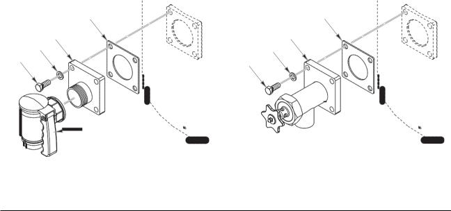
DRAW-OFF VALVES
Install the draw-off valve, if equipped. Install items 1 thru 5 for the plug style valve or items 1 thru 3 and item 6 for the compression style valve.
3 |
3 |
4 |
6 |
2 |
2 |
1 |
1 |
|
5 |
|
PLUG |
COMPRESSION |
DRAW -OFF VALVE |
DRAW -OFF VALVE |
— 5 —
GAS KETTLES
GAS CONNECTIONS
 Gas supply connections and any pipe joint compound must be resistant to the action of propane gases.
Codes require that a gas shutoff valve be installed in the gas line ahead of the kettle.
Connect the gas supply line to the gas valve on the kettle. Make sure the pipes are clean and free of obstructions, dirt and piping compound.
The gas line must be capable of delivering gas to the kettle without excessive pressure drop at the rate specified on the nameplate. Suggested gas supply line pressure is 7" Water Column (1.75 kPa) for natural gas and 11" Water Column (2.75 kPa) for propane. Burner manifold pressure is (-)1.4" Water Column (0.350kPa) for natural gas and (-)1.4" Water Column (0.350 kPa) for propane.
The proper sizing and installation of the gas connection is important for the machine to operate within its design specifications. In some installations, the gas supply may not be sufficient enough to allow all the gas equipment to operate properly at peak loads; or when other equipment with a high BTU/ hr. input requirement is operating. The connection to the machine becomes even more important in this type of location. Flexible gas connectors with quick disconnect or swivel fittings (when used) and gas connectors beyond the length necessary will reduce the BTU/hr. flow capacity to the machine.
NOTE: Do not use corrugated stainless steel tubing for commercial gas equipment supply connections.
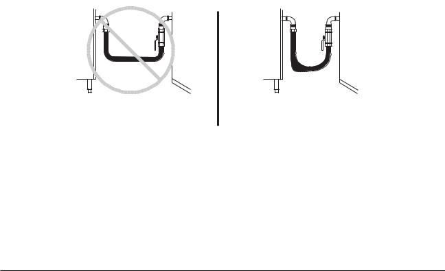
NOTE: A straight gas connection is the ideal condition for the rated BTU/hr. flow capacity of the connector. If a straight connection is not possible and a flexible gas connector is used, do not twist, kink or excessively flex the connector beyond a U shape. Flexing the gas connector as described will restrict gas flow or may damage the connector.
Changing a flexible gas connector may raise the BTU/hr. flow capacity enough to allow the machine to operate within its design specifications. (i.e. Removing the quick disconnect fitting, installing a shorter gas connector or installing a larger diameter gas connector.) An alternative may be to move the equipment to a different gas supply location in the kitchen. (i.e. Closer to the main supply into the kitchen or away from other equipment with high BTU/hr. input requirements.)
KETTLE |
WALL |
KETTLE |
WALL |
INCORRECT INSTALLATION |
CORRECT INSTALLATION |
 Prior to lighting, check all joints in the gas supply line for leaks. Use soap and water solution. Do not use an open flame.
After piping has been checked for leaks, all piping receiving gas should be fully purged to remove air.
— 6 —
 Loading...