


SERVICE MANUAL
Electric Stationary and Tilting
Kettles
K20EL ML-136073
K40EL ML-136074
K60EL ML-136075
K20ELT ML-136077
K40ELT ML-136078
K60ELT ML-136079
- NOTICE -
This Manual is prepared for the use of trained Vulcan Service Technicians and should not be used by those not properly qualified.
This manual is not intended to be all encompassing. If you have not attended a Vulcan Service School for this product, you should read, in its entirety, the repair procedure you wish to perform to determine if you have the necessary tools, instruments and skills required to perform the procedure. Procedures for which you do not have the necessary tools, instruments and skills should be performed by a trained Vulcan Service Technician.
The reproduction, transfer, sale or other use of this Manual, without the express written consent of Vulcan, is prohibited.
This manual has been provided to you by ITW Food Equipment Group LLC ("ITW FEG") without charge and remains the property of ITW FEG, and by accepting this manual you agree that you will return it to ITW FEG promptly upon its request for such return at any time in the future.
A product of Vulcan-Hart |
3600 North Point Blvd Baltimore, MD 21222 |
|
F45472 (1112) |

Electric Stationary and Tilting Kettles
TABLE OF CONTENTS
General . . . . . . . . . . . . . . . . . . . . . . . . . . . . . . . . . . . . . . . . . . . . . . . . . . . . . . . . . . . . . . . . . . . . . . . . . . . . . . . . . . . . . . . . . . . . . . . . . . . . 3 INTRODUCTION . . . . . . . . . . . . . . . . . . . . . . . . . . . . . . . . . . . . . . . . . . . . . . . . . . . . . . . . . . . . . . . . . . . . . . . . . . . . . . . . . . . . . . . 3 GENERAL . . . . . . . . . . . . . . . . . . . . . . . . . . . . . . . . . . . . . . . . . . . . . . . . . . . . . . . . . . . . . . . . . . . . . . . . . . . . . . . . . . . . . . . . . . 3 STATIONARY AND TILTING KETTLES . . . . . . . . . . . . . . . . . . . . . . . . . . . . . . . . . . . . . . . . . . . . . . . . . . . . . . . . . . . . . 3 MODELS COVERED . . . . . . . . . . . . . . . . . . . . . . . . . . . . . . . . . . . . . . . . . . . . . . . . . . . . . . . . . . . . . . . . . . . . . . . . . . . . . . . . . . . 3 CONTROL PANEL . . . . . . . . . . . . . . . . . . . . . . . . . . . . . . . . . . . . . . . . . . . . . . . . . . . . . . . . . . . . . . . . . . . . . . . . . . . . . . . . . . . . . 3 TOOLS . . . . . . . . . . . . . . . . . . . . . . . . . . . . . . . . . . . . . . . . . . . . . . . . . . . . . . . . . . . . . . . . . . . . . . . . . . . . . . . . . . . . . . . . . . . . . . . . . 3 SPECIFICATIONS . . . . . . . . . . . . . . . . . . . . . . . . . . . . . . . . . . . . . . . . . . . . . . . . . . . . . . . . . . . . . . . . . . . . . . . . . . . . . . . . . . . . . . 4 OPERATION, CLEANING AND MAINTAINENCE . . . . . . . . . . . . . . . . . . . . . . . . . . . . . . . . . . . . . . . . . . . . . . . . . . . . . . . . 4
REMOVAL AND REPLACEMENT OF PARTS . . . . . . . . . . . . . . . . . . . . . . . . . . . . . . . . . . . . . . . . . . . . . . . . . . . . . . . . . . . . . . . 5 CONTROL BOX COVER . . . . . . . . . . . . . . . . . . . . . . . . . . . . . . . . . . . . . . . . . . . . . . . . . . . . . . . . . . . . . . . . . . . . . . . . . . . . . . . 5 BOTTOM COVER . . . . . . . . . . . . . . . . . . . . . . . . . . . . . . . . . . . . . . . . . . . . . . . . . . . . . . . . . . . . . . . . . . . . . . . . . . . . . . . . . . . . . . 5 COMPONENT PANELS . . . . . . . . . . . . . . . . . . . . . . . . . . . . . . . . . . . . . . . . . . . . . . . . . . . . . . . . . . . . . . . . . . . . . . . . . . . . . . . . 5 HEATING CONTACTORS . . . . . . . . . . . . . . . . . . . . . . . . . . . . . . . . . . . . . . . . . . . . . . . . . . . . . . . . . . . . . . . . . . . . . . . . . . . . . . 6 TEMPERATURE CONTROLLER . . . . . . . . . . . . . . . . . . . . . . . . . . . . . . . . . . . . . . . . . . . . . . . . . . . . . . . . . . . . . . . . . . . . . . . . 6 WATER LEVEL CONTROL . . . . . . . . . . . . . . . . . . . . . . . . . . . . . . . . . . . . . . . . . . . . . . . . . . . . . . . . . . . . . . . . . . . . . . . . . . . . . 6 MAIN TRANSFORMER . . . . . . . . . . . . . . . . . . . . . . . . . . . . . . . . . . . . . . . . . . . . . . . . . . . . . . . . . . . . . . . . . . . . . . . . . . . . . . . . . 7 HEATING ELEMENT . . . . . . . . . . . . . . . . . . . . . . . . . . . . . . . . . . . . . . . . . . . . . . . . . . . . . . . . . . . . . . . . . . . . . . . . . . . . . . . . . . . 7 WATER LEVEL PROBE (LLCO) . . . . . . . . . . . . . . . . . . . . . . . . . . . . . . . . . . . . . . . . . . . . . . . . . . . . . . . . . . . . . . . . . . . . . . . . 9 TEMPERATURE SENSOR . . . . . . . . . . . . . . . . . . . . . . . . . . . . . . . . . . . . . . . . . . . . . . . . . . . . . . . . . . . . . . . . . . . . . . . . . . . . 10 PRESSURE SWITCH . . . . . . . . . . . . . . . . . . . . . . . . . . . . . . . . . . . . . . . . . . . . . . . . . . . . . . . . . . . . . . . . . . . . . . . . . . . . . . . . . 10 POTENTIOMETER . . . . . . . . . . . . . . . . . . . . . . . . . . . . . . . . . . . . . . . . . . . . . . . . . . . . . . . . . . . . . . . . . . . . . . . . . . . . . . . . . . . . 11 SWITCH ASSEMBLY . . . . . . . . . . . . . . . . . . . . . . . . . . . . . . . . . . . . . . . . . . . . . . . . . . . . . . . . . . . . . . . . . . . . . . . . . . . . . . . . . . 11 GEARBOX (TILT MODELS ONLY) . . . . . . . . . . . . . . . . . . . . . . . . . . . . . . . . . . . . . . . . . . . . . . . . . . . . . . . . . . . . . . . . . . . . . 12 TILT BEARING . . . . . . . . . . . . . . . . . . . . . . . . . . . . . . . . . . . . . . . . . . . . . . . . . . . . . . . . . . . . . . . . . . . . . . . . . . . . . . . . . . . . . . . . 12
SERVICE PROCEDURES AND ADJUSTMENTS . . . . . . . . . . . . . . . . . . . . . . . . . . . . . . . . . . . . . . . . . . . . . . . . . . . . . . . . . . . 14 TEMPERATURE CONTROLLER TEST . . . . . . . . . . . . . . . . . . . . . . . . . . . . . . . . . . . . . . . . . . . . . . . . . . . . . . . . . . . . . . . . 14 POTENTIOMETER TEST . . . . . . . . . . . . . . . . . . . . . . . . . . . . . . . . . . . . . . . . . . . . . . . . . . . . . . . . . . . . . . . . . . . . . . . . . . . . . . 15 THERMOCOUPLE TEST . . . . . . . . . . . . . . . . . . . . . . . . . . . . . . . . . . . . . . . . . . . . . . . . . . . . . . . . . . . . . . . . . . . . . . . . . . . . . . 15 VENTING . . . . . . . . . . . . . . . . . . . . . . . . . . . . . . . . . . . . . . . . . . . . . . . . . . . . . . . . . . . . . . . . . . . . . . . . . . . . . . . . . . . . . . . . . . . . . 15 FILLING THE RESERVOIR JACKET . . . . . . . . . . . . . . . . . . . . . . . . . . . . . . . . . . . . . . . . . . . . . . . . . . . . . . . . . . . . . . . . . . . 16
PARTIAL REFILL . . . . . . . . . . . . . . . . . . . . . . . . . . . . . . . . . . . . . . . . . . . . . . . . . . . . . . . . . . . . . . . . . . . . . . . . . . . . . . . . . . 16 COMPLETE DRAINING AND REFILL . . . . . . . . . . . . . . . . . . . . . . . . . . . . . . . . . . . . . . . . . . . . . . . . . . . . . . . . . . . . . . 17 HEATING ELEMENT . . . . . . . . . . . . . . . . . . . . . . . . . . . . . . . . . . . . . . . . . . . . . . . . . . . . . . . . . . . . . . . . . . . . . . . . . . . . . . . . . . 18 KETTLE TILT ADJUSTMENT (TILT MODELS ONLY) . . . . . . . . . . . . . . . . . . . . . . . . . . . . . . . . . . . . . . . . . . . . . . . . . . 18
ELECTRICAL OPERATION . . . . . . . . . . . . . . . . . . . . . . . . . . . . . . . . . . . . . . . . . . . . . . . . . . . . . . . . . . . . . . . . . . . . . . . . . . . . . . . . 20 COMPONENT FUNCTION . . . . . . . . . . . . . . . . . . . . . . . . . . . . . . . . . . . . . . . . . . . . . . . . . . . . . . . . . . . . . . . . . . . . . . . . . . . . 20 COMPONENT LOCATION . . . . . . . . . . . . . . . . . . . . . . . . . . . . . . . . . . . . . . . . . . . . . . . . . . . . . . . . . . . . . . . . . . . . . . . . . . . . . 21 WATER LEVEL CONTROL (WLC LLCO) . . . . . . . . . . . . . . . . . . . . . . . . . . . . . . . . . . . . . . . . . . . . . . . . . . . . . . . . . . . . . . 22 SEQUENCE OF OPERATION . . . . . . . . . . . . . . . . . . . . . . . . . . . . . . . . . . . . . . . . . . . . . . . . . . . . . . . . . . . . . . . . . . . . . . . . . 23 SCHEMATIC DIAGRAM . . . . . . . . . . . . . . . . . . . . . . . . . . . . . . . . . . . . . . . . . . . . . . . . . . . . . . . . . . . . . . . . . . . . . . . . . . . . . . . 25 WIRING DIAGRAMS . . . . . . . . . . . . . . . . . . . . . . . . . . . . . . . . . . . . . . . . . . . . . . . . . . . . . . . . . . . . . . . . . . . . . . . . . . . . . . . . . . 26
TROUBLESHOOTING . . . . . . . . . . . . . . . . . . . . . . . . . . . . . . . . . . . . . . . . . . . . . . . . . . . . . . . . . . . . . . . . . . . . . . . . . . . . . . . . . . . . . 29 TROUBLESHOOTING . . . . . . . . . . . . . . . . . . . . . . . . . . . . . . . . . . . . . . . . . . . . . . . . . . . . . . . . . . . . . . . . . . . . . . . . . . . . . . . . . 29
© VULCAN 2012 |
|
F45472 (1112) |
Page 2 of 29 |
Electric Stationary and Tilting Kettles - General
General
INTRODUCTION
General
The procedures in this manual apply to all models unless otherwise specified. The pictures and illustrations are of a model K40ELT kettle unless otherwise noted. All information and specifications contained in this manual are based on the latest product information available at the time of printing.
Stationary and Tilting Kettles
The electric stationary and tilting kettles are self contained two thirds jacketed kettles. The lower two thirds of the kettle bowl is a double wall stainless steel construction that provides a reservoir for a solution of heat transfer fluid and distilled water for improved heating of the kettle contents. The kettles are used to prepare a variety of liquid or semi-liquid food products such as soups, stews and sauces.
MODELS COVERED
Electric Stationary and Tilting Kettles
K20EL Stationary Kettle - 20 Gallon
K40EL Stationary Kettle - 40 Gallon
K60EL Stationary Kettle - 60 Gallon
K20ELT Tilting Kettle - 20 Gallon
K40ELT Tilting Kettle - 40 Gallon
K60ELT Tilting Kettle - 60 Gallon
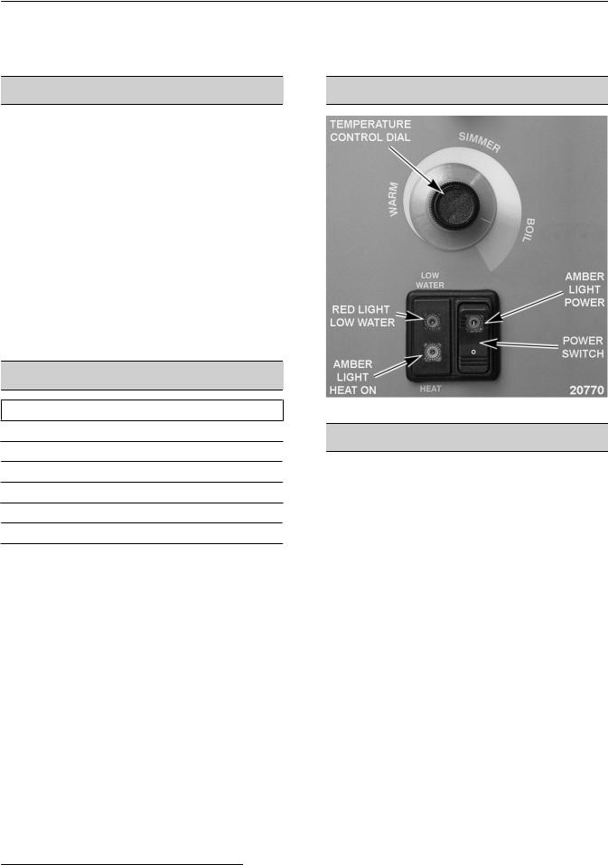
CONTROL PANEL
Fig. 1
TOOLS
Standard
•Standard set of hand tools.
•Pipe thread sealant.
•VOM with an AC current tester (meter sensitivity should be at least 20,000 ohms per volt).
•Temperature meter (thermocouple type). Use for checking kettle temperature.
•6 gallon container to hold drained reservoir jacket fluid.
Special
•Torque wrench (ft-lbs) for tightening heating element mounting bolts.
•Dowfrost heat transfer fluid Part No. 558038 (5 gallon). Refer to service procedures for volumes.
•Water - Use only distilled water only for re-filling of the jacket (purchase locally).
Page 3 of 29 |
|
F45472 (1112) |
|

Electric Stationary and Tilting Kettles - General
SPECIFICATIONS
Reservoir Jacket Fluid
•Water - Use only distilled water for partial re-filling of the jacket (purchase locally).
•Dowfrost heat transfer fluid Part No. 558038 (5 gallon). Use during a complete re-fill of the jacket with new fluid. Refer to service procedures for volumes.
ELECTRICAL SPECIFICATIONS
MODEL |
KW |
|
PHASE |
Amperage per Line |
Minimum Circuit Ampacity |
||||
|
208V |
240V |
480V |
208V |
240V |
480V |
|||
|
|
|
|
||||||
|
12 |
1 |
|
57.7 |
--- |
--- |
75 |
--- |
--- |
|
|
|
|
|
|
|
|
|
|
K20EL/ELT |
3 |
|
33.3 |
--- |
14.4 |
45 |
--- |
20 |
|
|
|
||||||||
|
|
|
|
|
|
|
|
|
|
16 |
1 |
|
--- |
66.7 |
--- |
--- |
85 |
--- |
|
|
|
||||||||
|
|
|
|
|
|
|
|
|
|
|
3 |
|
--- |
38.5 |
--- |
--- |
50 |
--- |
|
|
|
|
|||||||
|
|
|
|
|
|
|
|
|
|
K40EL/ELT |
18 |
3 |
|
50.0 |
43.3 |
21.7 |
65 |
55 |
30 |
K60EL/ELT |
|
||||||||
|
|
|
|
|
|
|
|
|
|
|
|
|
|
|
|
|
|
|
|
K40EL/ELT |
24 |
3 |
|
66.6 |
57.7 |
28.9 |
85 |
75 |
40 |
K60EL/ELT |
|
||||||||
|
|
|
|
|
|
|
|
|
|
|
|
|
|
|
|
|
|
|
|
The 208/240V electric kettles are wired from the factory for a 208V 3-phase supply. If connecting to 240V 3-phase supply, the primary voltage tap on the transformer must be changed to this voltage. For connecting to a single phase supply, the wiring between terminal block and contactors must be changed as shown in the WIRING DIAGRAMS.
OPERATION, CLEANING AND
MAINTAINENCE
Refer to F35457 Installation & Operation Manual for specific instructions. The manual includes:
•A page from the Stainless Steel Care and Cleaning Guide for proper care and cleaning of stainless steel.
•Draw-Off Valve and Plug Valve dissassembly & cleaning instructions.
F45472 (1112) |
|
Page 4 of 29 |
|

Electric Stationary and Tilting Kettles - REMOVAL AND REPLACEMENT OF PARTS
REMOVAL AND REPLACEMENT OF PARTS
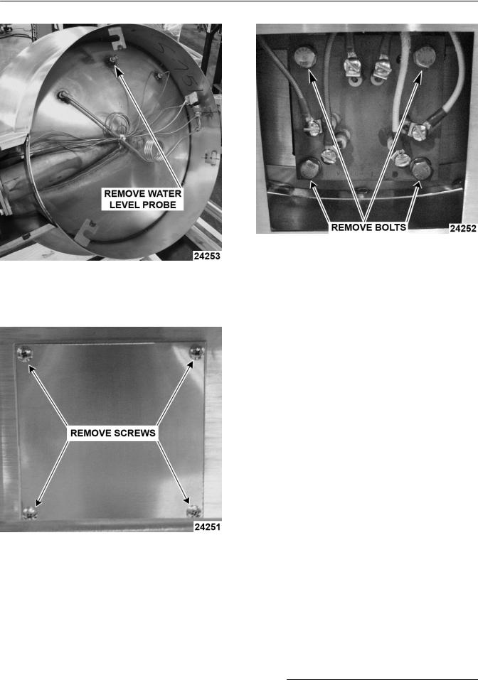
CONTROL BOX COVER
 Disconnect the
electrical power to the machine and follow lockout / tagout procedures.
Control Box Cover
BOTTOM COVER
 Disconnect the
electrical power to the machine and follow lockout / tagout procedures.
COMPONENT PANELS
 Disconnect the
electrical power to the machine and follow lockout / tagout procedures.
The following pictures show the Stationary Kettle, the Tilting Kettle and the Bottom component panels. Use these pictures to asist in removal and replacement of the components in these kettles.
Stationary Kettle
Tilting Kettle
Bottom Cover
Page 5 of 29 |
|
F45472 (1112) |
|
Electric Stationary and Tilting Kettles - REMOVAL AND REPLACEMENT OF PARTS
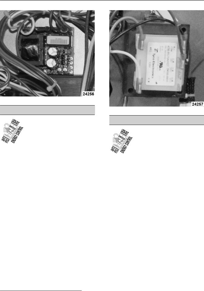
TEMPERATURE CONTROLLER
 Disconnect the
electrical power to the machine and follow lockout / tagout procedures.
1.Remove CONTROL BOX COVER.
2.Disconnect lead wires from temperature controller.
3.Remove screws securing the temperature controller to panel.
4.Reverse procedure to install and check for proper operation.
Bottom
HEATING CONTACTORS
 Disconnect the
electrical power to the machine and follow lockout / tagout procedures.
1.Remove CONTROL BOX COVER.
2.Note location of lead wires then disconnect the wires from contactor being replaced.
3.Remove screws securing the contactor to panel.
4.Reverse procedure to install and check for proper operation.
Fig. 7
Fig. 8
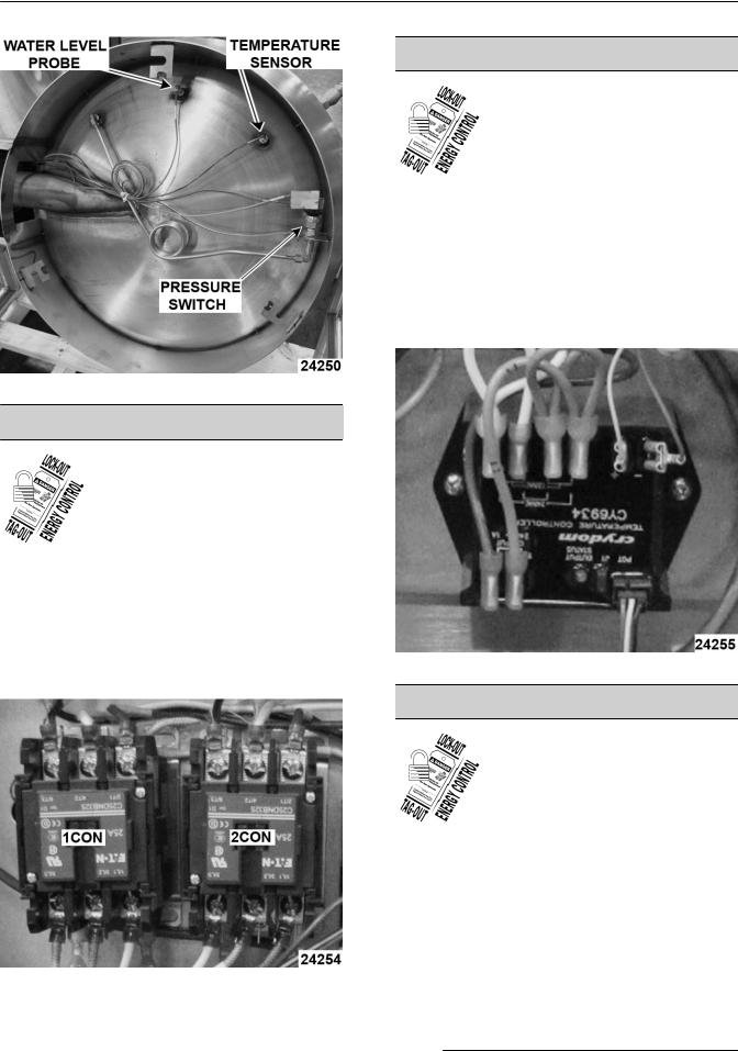
WATER LEVEL CONTROL
 Disconnect the
electrical power to the machine and follow lockout / tagout procedures.
1.Remove CONTROL BOX COVER.
2.Disconnect lead wires from the water level control.
3.Remove screws securing the water level control to panel.
4.Reverse procedure to install and check for proper operation.
F45472 (1112) |
|
Page 6 of 29 |
|
Electric Stationary and Tilting Kettles - REMOVAL AND REPLACEMENT OF PARTS
Fig. 9
MAIN TRANSFORMER
 Disconnect the
electrical power to the machine and follow lockout / tagout procedures.
1.Remove CONTROL BOX COVER.
2.Disconnect lead wires from the transformer.
3.Remove screws securing the transformer to panel.
4.Reverse procedure to install and check for proper operation.
Fig. 10
HEATING ELEMENT
 Disconnect the
electrical power to the machine and follow lockout / tagout procedures.
TILTING KETTLE
1.Open pressure relief valve until reservoir jacket is completely vented.
2.Remove BOTTOM COVER.
3.Remove wire from water level probe (LLCO).
4.Place a large container under the kettle. Remove water level probe (LLCO) and open the fill valve (40 & 60 gallon kettles) or remove pipe plug from fill elbow (20 gallon kettles) to vent the jacket and drain liquid from kettle.
Page 7 of 29 |
|
F45472 (1112) |
|
Electric Stationary and Tilting Kettles - REMOVAL AND REPLACEMENT OF PARTS
Fig. 11
NOTE: If liquid drained from kettle is still clean, save for reuse.
5.Remove heater access cover.
Fig. 12
6.Note lead wire locations and disconnect wires from heating element.
7.Remove mounting bolts securing heating element to kettle.
Fig. 13
8.Remove heating element from kettle.
9.Reverse procedure to install. Use a new heating element seal whenever installing heating element. Torque mounting nuts to 40 ft-lbs and tighten in an alternating pattern.
10.Refill jacket with fluid. See FILLING THE RESERVOIR JACKET.
11.Remove air from reservoir jacket as outlined under VENTING.
12.Check for proper operation and leaks around heating element.
STATIONARY KETTLE
1.Open pressure relief valve until reservoir jacket is completely vented.
2.Remove BOTTOM COVER.
3.Remove wire from Water Level Probe (LLCO).
4.Place a large container under the kettle. Remove water level probe (LLCO) and open the fill valve (40 & 60 gallon kettles) or remove pipe plug from fill elbow (20 gallon kettles) to vent the jacket and drain liquid from kettle.
F45472 (1112) |
|
Page 8 of 29 |
|
Electric Stationary and Tilting Kettles - REMOVAL AND REPLACEMENT OF PARTS
Fig. 14
NOTE: If liquid drained from kettle is still clean, save for reuse.
5.Remove CONTROL BOX COVER.
6.Note lead wire locations and disconnect wires from heating element.
7.Remove mounting nuts securing heating element to kettle.
Fig. 15
8.Remove heating element from kettle.
9.Reverse procedure to install. Use a new heating element seal whenever installing heating element. Torque mounting bolts to 40 ft-lbs and tighten in an alternating pattern.
10.Refill jacket with fluid. See FILLING THE RESERVOIR JACKET.
11.Remove air from reservoir jacket as outlined under VENTING.
12.Check for proper operation and leaks around heating element.
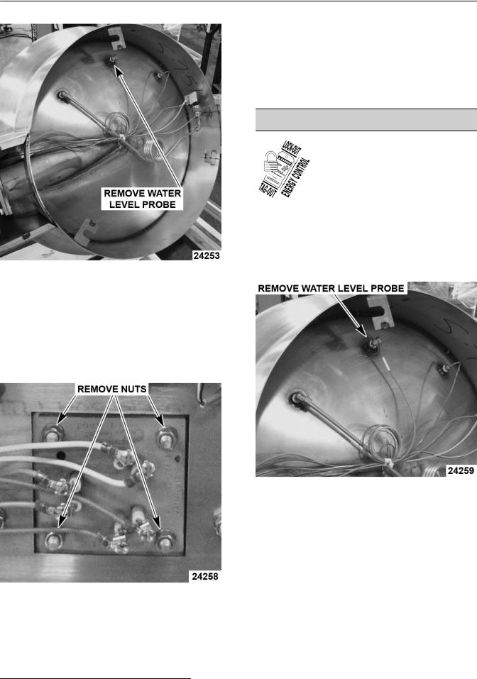
WATER LEVEL PROBE (LLCO)
 Disconnect the
electrical power to the machine and follow lockout / tagout procedures.
1.Open pressure relief valve until reservoir jacket is completely vented.
2.Remove BOTTOM COVER.
3.Disconnect lead wires from the water level probe .
Fig. 16
4.Place a large container under kettle to catch liquid that drains from kettle.
NOTE: If liquid drained from kettle is still clean, save for reuse.
5.Remove component from bottom of kettle.
6.Reverse procedure to install.
NOTE: Clean threads and apply pipe thread sealant when replacing water level probe.
7.Refill jacket with fluid. See FILLING THE RESERVOIR JACKET.
8.Remove air from reservoir jacket as outlined under VENTING.
Page 9 of 29 |
|
F45472 (1112) |
|
 Loading...