


SERVICE MANUAL
ELECTRIC
COMBI
OVENS
MODEL ML
VCE6H 126177
VCE10H 126178
VCE10F 126179
VCE20H 126172
VCE20F 126173
VCE10F SHOWN ON STAND
- NOTICE -
This Manual is prepared for the use of trained Vulcan Service Technicians and should not be used by those not properly qualified. If you have attended a Vulcan Service School for this product, you may be qualified to perform all the procedures described in this manual.
This manual is not intended to be all encompassing. If you have not attended a Vulcan Service School for this product, you should read, in its entirety, the repair procedure you wish to perform to determine if you have the necessary tools, instruments and skills required to perform the procedure. Procedures for which you do not have the necessary tools, instruments and skills should be performed by a trained Vulcan Service Technician.
Reproduction or other use of this Manual, without the express written consent of Vulcan-Hart, is prohibited.
A product of VULCAN-HART |
LOUISVILLE, KY 40201-0696 |
Form 24659 (September 1999) |
|

ELECTRIC COMBI OVENS |
|
TABLE OF CONTENTS |
|
GENERAL . . . . . . . . . . . . . . . . . . . . . . . . . . . . . . . . . . . . . . . . . . . . . . . . . . . . . . . . . . . . . . . . . . . . . . . . . . . . . |
4 |
Introduction . . . . . . . . . . . . . . . . . . . . . . . . . . . . . . . . . . . . . . . . . . . . . . . . . . . . . . . . . . . . . . . . . . . . . . . . |
4 |
Operation . . . . . . . . . . . . . . . . . . . . . . . . . . . . . . . . . . . . . . . . . . . . . . . . . . . . . . . . . . . . . . . . . . . . . . . . . . |
4 |
Cleaning . . . . . . . . . . . . . . . . . . . . . . . . . . . . . . . . . . . . . . . . . . . . . . . . . . . . . . . . . . . . . . . . . . . . . . . . . . |
4 |
Stacking Kit Instructions . . . . . . . . . . . . . . . . . . . . . . . . . . . . . . . . . . . . . . . . . . . . . . . . . . . . . . . . . . . . . . . |
4 |
Specifications . . . . . . . . . . . . . . . . . . . . . . . . . . . . . . . . . . . . . . . . . . . . . . . . . . . . . . . . . . . . . . . . . . . . . . |
4 |
Water Supply . . . . . . . . . . . . . . . . . . . . . . . . . . . . . . . . . . . . . . . . . . . . . . . . . . . . . . . . . . . . . . . . . . . |
4 |
Electrical . . . . . . . . . . . . . . . . . . . . . . . . . . . . . . . . . . . . . . . . . . . . . . . . . . . . . . . . . . . . . . . . . . . . . . |
5 |
Oven Controls . . . . . . . . . . . . . . . . . . . . . . . . . . . . . . . . . . . . . . . . . . . . . . . . . . . . . . . . . . . . . . . . . . . . . . |
6 |
Water Conditioning . . . . . . . . . . . . . . . . . . . . . . . . . . . . . . . . . . . . . . . . . . . . . . . . . . . . . . . . . . . . . . . . . . |
7 |
Lubrication . . . . . . . . . . . . . . . . . . . . . . . . . . . . . . . . . . . . . . . . . . . . . . . . . . . . . . . . . . . . . . . . . . . . . . . . . |
7 |
Tools . . . . . . . . . . . . . . . . . . . . . . . . . . . . . . . . . . . . . . . . . . . . . . . . . . . . . . . . . . . . . . . . . . . . . . . . . . . . . |
7 |
REMOVAL AND REPLACEMENT OF PARTS . . . . . . . . . . . . . . . . . . . . . . . . . . . . . . . . . . . . . . . . . . . . . . . . . |
8 |
Rack Guide/Filter/Exhaust Assembly . . . . . . . . . . . . . . . . . . . . . . . . . . . . . . . . . . . . . . . . . . . . . . . . . . . . . |
8 |
Covers and Panels . . . . . . . . . . . . . . . . . . . . . . . . . . . . . . . . . . . . . . . . . . . . . . . . . . . . . . . . . . . . . . . . . . . |
8 |
Oven Temperature Probe . . . . . . . . . . . . . . . . . . . . . . . . . . . . . . . . . . . . . . . . . . . . . . . . . . . . . . . . . . . . . |
9 |
Programable Oven Control . . . . . . . . . . . . . . . . . . . . . . . . . . . . . . . . . . . . . . . . . . . . . . . . . . . . . . . . . . . |
10 |
Manual Oven Controls . . . . . . . . . . . . . . . . . . . . . . . . . . . . . . . . . . . . . . . . . . . . . . . . . . . . . . . . . . . . . . . |
11 |
Relay Board . . . . . . . . . . . . . . . . . . . . . . . . . . . . . . . . . . . . . . . . . . . . . . . . . . . . . . . . . . . . . . . . . . . . . . . |
11 |
Blower and Motor . . . . . . . . . . . . . . . . . . . . . . . . . . . . . . . . . . . . . . . . . . . . . . . . . . . . . . . . . . . . . . . . . . . |
12 |
Blower Motor Shaft Seal . . . . . . . . . . . . . . . . . . . . . . . . . . . . . . . . . . . . . . . . . . . . . . . . . . . . . . . . . . . . . |
13 |
Heating Elements . . . . . . . . . . . . . . . . . . . . . . . . . . . . . . . . . . . . . . . . . . . . . . . . . . . . . . . . . . . . . . . . . . |
13 |
Thermal Fuse(s) . . . . . . . . . . . . . . . . . . . . . . . . . . . . . . . . . . . . . . . . . . . . . . . . . . . . . . . . . . . . . . . . . . . |
14 |
Steam Generator Drain Pump . . . . . . . . . . . . . . . . . . . . . . . . . . . . . . . . . . . . . . . . . . . . . . . . . . . . . . . . . |
15 |
Vent Damper Assembly . . . . . . . . . . . . . . . . . . . . . . . . . . . . . . . . . . . . . . . . . . . . . . . . . . . . . . . . . . . . . . |
15 |
Water Level Sensors and Water Equalization Tube . . . . . . . . . . . . . . . . . . . . . . . . . . . . . . . . . . . . . . . . . |
16 |
Steam Generator Tank . . . . . . . . . . . . . . . . . . . . . . . . . . . . . . . . . . . . . . . . . . . . . . . . . . . . . . . . . . . . . . |
17 |
Oven Door . . . . . . . . . . . . . . . . . . . . . . . . . . . . . . . . . . . . . . . . . . . . . . . . . . . . . . . . . . . . . . . . . . . . . . . . |
18 |
Door Lamp . . . . . . . . . . . . . . . . . . . . . . . . . . . . . . . . . . . . . . . . . . . . . . . . . . . . . . . . . . . . . . . . . . . . . . . . |
19 |
Oven Door Hinges . . . . . . . . . . . . . . . . . . . . . . . . . . . . . . . . . . . . . . . . . . . . . . . . . . . . . . . . . . . . . . . . . . |
19 |
Door Magnetic Reed Switch . . . . . . . . . . . . . . . . . . . . . . . . . . . . . . . . . . . . . . . . . . . . . . . . . . . . . . . . . . . |
20 |
Door Seal . . . . . . . . . . . . . . . . . . . . . . . . . . . . . . . . . . . . . . . . . . . . . . . . . . . . . . . . . . . . . . . . . . . . . . . . . |
20 |
Door Locking Mechanism . . . . . . . . . . . . . . . . . . . . . . . . . . . . . . . . . . . . . . . . . . . . . . . . . . . . . . . . . . . . . |
20 |
Oven Cavity Seal . . . . . . . . . . . . . . . . . . . . . . . . . . . . . . . . . . . . . . . . . . . . . . . . . . . . . . . . . . . . . . . . . . . |
21 |
Power Supply Board and Transformer . . . . . . . . . . . . . . . . . . . . . . . . . . . . . . . . . . . . . . . . . . . . . . . . . . . |
22 |
Contactors . . . . . . . . . . . . . . . . . . . . . . . . . . . . . . . . . . . . . . . . . . . . . . . . . . . . . . . . . . . . . . . . . . . . . . . . |
22 |
Oven Cavity Drain . . . . . . . . . . . . . . . . . . . . . . . . . . . . . . . . . . . . . . . . . . . . . . . . . . . . . . . . . . . . . . . . . . |
23 |
SERVICE PROCEDURES AND ADJUSTMENTS . . . . . . . . . . . . . . . . . . . . . . . . . . . . . . . . . . . . . . . . . . . . . . 24
Configuration Mode - Programable Control . . . . . . . . . . . . . . . . . . . . . . . . . . . . . . . . . . . . . . . . . . . . . . . 24
Diagnostic Test Mode - Programable Control . . . . . . . . . . . . . . . . . . . . . . . . . . . . . . . . . . . . . . . . . . . . . . 25
Configuration Mode - Manual Controls . . . . . . . . . . . . . . . . . . . . . . . . . . . . . . . . . . . . . . . . . . . . . . . . . . . 26
Diagnostic Test Mode - Manual Controls . . . . . . . . . . . . . . . . . . . . . . . . . . . . . . . . . . . . . . . . . . . . . . . . . 28
Service Error Lights . . . . . . . . . . . . . . . . . . . . . . . . . . . . . . . . . . . . . . . . . . . . . . . . . . . . . . . . . . . . . . . . . 29
Heating Elements . . . . . . . . . . . . . . . . . . . . . . . . . . . . . . . . . . . . . . . . . . . . . . . . . . . . . . . . . . . . . . . . . . 30
Oven Door Adjustment . . . . . . . . . . . . . . . . . . . . . . . . . . . . . . . . . . . . . . . . . . . . . . . . . . . . . . . . . . . . . . . 30
Buzzer Adjustment - Programable Control . . . . . . . . . . . . . . . . . . . . . . . . . . . . . . . . . . . . . . . . . . . . . . . . 32
Buzzer Adjustment - Manual Controls . . . . . . . . . . . . . . . . . . . . . . . . . . . . . . . . . . . . . . . . . . . . . . . . . . . 32
Clean Cycle Mode - Steam Generator Deliming . . . . . . . . . . . . . . . . . . . . . . . . . . . . . . . . . . . . . . . . . . . . 33
Battery Backup - Programable Control . . . . . . . . . . . . . . . . . . . . . . . . . . . . . . . . . . . . . . . . . . . . . . . . . . . 35
Page 2 of 68

ELECTRIC COMBI OVENS
ELECTRICAL OPERATION . . . . . . . . . . . . . . . . . . . . . . . . . . . . . . . . . . . . . . . . . . . . . . . . . . . . . . . . . . . . . . 37
Component Function . . . . . . . . . . . . . . . . . . . . . . . . . . . . . . . . . . . . . . . . . . . . . . . . . . . . . . . . . . . . . . . . 37
Component Location . . . . . . . . . . . . . . . . . . . . . . . . . . . . . . . . . . . . . . . . . . . . . . . . . . . . . . . . . . . . . . . . 40
Sequence of Operation . . . . . . . . . . . . . . . . . . . . . . . . . . . . . . . . . . . . . . . . . . . . . . . . . . . . . . . . . . . . . . 42
Heating Mode and Cavity Fan Speeds . . . . . . . . . . . . . . . . . . . . . . . . . . . . . . . . . . . . . . . . . . . . . . . 42
Heating Regulation . . . . . . . . . . . . . . . . . . . . . . . . . . . . . . . . . . . . . . . . . . . . . . . . . . . . . . . . . . . . . . 42
Steam Pre-Heat . . . . . . . . . . . . . . . . . . . . . . . . . . . . . . . . . . . . . . . . . . . . . . . . . . . . . . . . . . . . . . . . 43
Steam Regulation . . . . . . . . . . . . . . . . . . . . . . . . . . . . . . . . . . . . . . . . . . . . . . . . . . . . . . . . . . . . . . . 43
Water Injection (Humidifier) . . . . . . . . . . . . . . . . . . . . . . . . . . . . . . . . . . . . . . . . . . . . . . . . . . . . . . . 44
Cool Down Mode (Manual Controls) . . . . . . . . . . . . . . . . . . . . . . . . . . . . . . . . . . . . . . . . . . . . . . . . . 44
Programable Oven Control . . . . . . . . . . . . . . . . . . . . . . . . . . . . . . . . . . . . . . . . . . . . . . . . . . . . . . . . 45
Manual Oven Controls . . . . . . . . . . . . . . . . . . . . . . . . . . . . . . . . . . . . . . . . . . . . . . . . . . . . . . . . . . . 49
Wiring Diagrams . . . . . . . . . . . . . . . . . . . . . . . . . . . . . . . . . . . . . . . . . . . . . . . . . . . . . . . . . . . . . . . . . . . 54
6 Level . . . . . . . . . . . . . . . . . . . . . . . . . . . . . . . . . . . . . . . . . . . . . . . . . . . . . . . . . . . . . . . . . . . . . . . 54
10 Level . . . . . . . . . . . . . . . . . . . . . . . . . . . . . . . . . . . . . . . . . . . . . . . . . . . . . . . . . . . . . . . . . . . . . . 56
20 Level . . . . . . . . . . . . . . . . . . . . . . . . . . . . . . . . . . . . . . . . . . . . . . . . . . . . . . . . . . . . . . . . . . . . . . 58
Electric Heater Circuits . . . . . . . . . . . . . . . . . . . . . . . . . . . . . . . . . . . . . . . . . . . . . . . . . . . . . . . . . . . . . . 60
TROUBLESHOOTING . . . . . . . . . . . . . . . . . . . . . . . . . . . . . . . . . . . . . . . . . . . . . . . . . . . . . . . . . . . . . . . . . . |
63 |
© VULCAN 1999
Page 3 of 68
ELECTRIC COMBI OVENS - GENERAL
GENERAL
INTRODUCTION
General
The procedures in this manual apply to all models unless otherwise specified. All of the information, illustrations and specifications contained in this manual are based on the latest product information available at the time of printing.
Combi Ovens
The Electric Combi ovens provide convection heat, steam heat or a combination of both in a single compartment cooking chamber. Humidification is provided from the internal steam generator or by water injection into the oven cavity. When the water is injected by means of an internal spray nozzle, it vaporizes on contact with the hot interior surfaces.
The ovens are available in two depths, Half and Full (half on 6 level only) and in three sizes (6H, 10H/F and 20H/F).
OPERATION
Refer to the Installation & Operation Manual for specific operating instructions.
CLEANING
STACKING KIT INSTRUCTIONS
When servicing stacked ovens and disassembly is required, refer to the Stacking Kit Instructions for specific assembly procedures.
SPECIFICATIONS
Water Supply
The fact that a water supply is potable is no guarantee that it is suitable for steam generation. The supply connection to the steam generator should be “treated” water and must be within the guidelines listed below. For drain water cooling only, an “untreated“ water supply connection should be used.
Supply Pressure |
20-80 psig |
|
(treated and untreated water) |
||
|
||
|
|
|
Supply Connections |
cold |
|
(treated and untreated water) |
||
|
||
|
|
|
Water Hardness * |
2-4 grains per |
|
gallon (gpg) |
||
|
||
Chloride |
less than 30 ppm |
|
|
|
|
PH factor (range) |
7 to 8 |
|
|
|
(*17.1 ppm = 1 grain of hardness)
Refer to the Installation & Operation Manual for specific cleaning instructions.
Page 4 of 68
ELECTRIC COMBI OVENS - GENERAL
Electrical
|
|
MACHINE AMPERAGE (3 PHASE/ 60HZ) 1 |
|||||||
|
|
|
|
|
|
|
|
||
MODEL |
POWER |
PER LINE 2 |
RECOMMENDED |
||||||
|
CIRCUIT |
|
|||||||
(KW) |
|
|
|||||||
|
|
|
|
PROTECTION 3 |
|||||
|
|
|
|
|
|||||
|
|
|
|
|
|
|
|
|
|
|
|
208V |
240V |
480V |
208V |
|
240V |
|
480V |
|
|
|
|
|
|
|
|
|
|
VCE6H |
9 |
25 |
22 |
11 |
35 |
|
30 |
|
15 |
|
|
|
|
|
|
|
|
|
|
VCE10H |
18 |
50 |
43 |
22 |
70 |
|
60 |
|
30 |
|
|
|
|
|
|
|
|
|
|
VCE10F |
18 |
50 |
43 |
22 |
70 |
|
60 |
|
30 |
|
|
|
|
|
|
|
|
|
|
VCE20H |
24 |
67 |
58 |
29 |
90 |
|
80 |
|
40 |
|
|
|
|
|
|
|
|
|
|
VCE20F |
36 |
100 |
87 |
43 |
125 |
|
110 |
|
60 |
|
|
|
|
|
|
|
|
|
|
NOTES: 1. Amperage values in the table are nominal. Tolerance is +5/-10%.
2.Line currents must be measured in full power convection heat mode.
3.Complied in accordance with National Electric Code, ANSI/NFPA 70, latest edition.
|
|
|
INDIVIDUAL AMPERAGE (3 PHASE/ 60HZ) 1 |
|
|
|||||
|
|
|
|
|
|
|
|
|
|
|
MODEL |
|
CONVECTION HEAT 2 |
|
STEAM GENERATOR HEAT 3 |
||||||
|
|
|
|
|
|
|
|
|
|
|
|
ELEMENTS |
208V |
240V |
480V |
ELEMENTS |
208V |
240V |
480V |
||
|
|
|
|
|
||||||
|
KW |
NO. |
KW |
NO. |
||||||
|
|
|
|
|
|
|
||||
|
|
|
|
|
|
|
|
|
|
|
VCE6H |
9 |
1 |
25 |
22 |
11 |
8 |
1 |
22 |
19 |
10 |
|
|
|
|
|
|
|
|
|
|
|
VCE10H |
9 |
2 |
50 |
43 |
22 |
8 |
2 |
45 |
39 |
19 |
|
|
|
|
|
|
|
|
|
|
|
VCE10F |
9 |
2 |
50 |
43 |
22 |
8 |
2 |
45 |
39 |
19 |
|
|
|
|
|
|
|
|
|
|
|
VCE20H |
6 |
4 |
67 |
58 |
29 |
8 |
3 |
67 |
58 |
29 |
|
|
|
|
|
|
|
|
|
|
|
VCE20F |
9 |
4 |
100 |
87 |
43 |
8 |
4 |
89 |
77 |
39 |
|
|
|
|
|
|
|
|
|
|
|
NOTES: 1. Amperage values in the table are nominal. Tolerance is +5/-10%.
2.Convection heater currents must be measured in full power convection heat mode.
3.Steam generator heater currents must be measured in full power steam mode.
Page 5 of 68

ELECTRIC COMBI OVENS - GENERAL
OVEN CONTROLS
PROGRAMMABLE |
|
DELUXE MANUAL |
STANDARD MANUAL |
|
|
|
|
|
|
|
|
|
|
|
Page 6 of 68

ELECTRIC COMBI OVENS - GENERAL
WATER CONDITIONING
Furnishing the steam generator with treated water to reduce scale formation is important. Scale formation will reduce steam output, cause premature component failure, and shorten equipment life. Most water supplies contain scale producing minerals such as Calcium and Magnesium. As steam is generated, the minerals remain and dissolve into the water. As the concentration of these minerals increases past a certain point, they precipitate from the water and coat the inside of the steam generator, heating elements, and water level sensors. Because of the high temperature of these surfaces, the precipitated minerals bake onto them and become very difficult to remove.
This may cause several problems:
1.Reduced heat transfer efficiency.
2.Premature heating element failures.
3.False readings from water level sensors.
These problems are common to any manufacturer's steamer regardless of design, but they can all be minimized by furnishing the steam generator with treated water.
Other factors affecting steam generation are iron content, amount of chloridation and dissolved gases.
The desired water properties can best be achieved by using a properly maintained water treatment system.
The water level probes in the steam generator use ions in the water to detect the water level. Do not use fully demineralized or de-ionized water since it is "non conductive" and the water level can not be detected.
The use of strainers, or filters will not remove minerals from the water.
Water supplies vary from state to state and from locations within a state. Therefore, Vulcan recommends that a local water treatment specialist be consulted before the installation of any steam generating equipment.
Steamers that operate over a long period of time without the benefit of a water treatment system, which have developed a heavy scale build up, should be cleaned before using the system.
LUBRICATION
Cavity fan motor has sealed bearings and requires no additional lubrication.
Cavity fan motor shaft seal requires lubrication at replacement (White silicone grease 544268).
TOOLS
Standard
Standard set of hand tools.
Metric set of hand tools.
VOM with AC current tester (any quality VOM with a sensitivity of at least 20,000 ohms can be used).
Gear puller to remove cavity fan.
Temperature meter with thermocouple.
Special
Red High Temperature RTV for door seal and probes (P/N 544313 or 542949).
Grounding kit to protect control board(s) if handled (P/N TL-84919).
Motor Shaft Centering Tool (P/N 359450).
28 pin EPROM extraction tool and 28 pin EPROM insertion tool (purchase locally).
Scalekleen deliming chemical or the recommended chemical for the water treatment system in use for deliming of the steam generator. (Scalekleen is available through the Service Parts Distribution Center or locally through an Everpure dealer)
Page 7 of 68
ELECTRIC COMBI OVEN - REMOVAL AND REPLACEMENT OF PARTS
REMOVAL AND REPLACEMENT OF PARTS
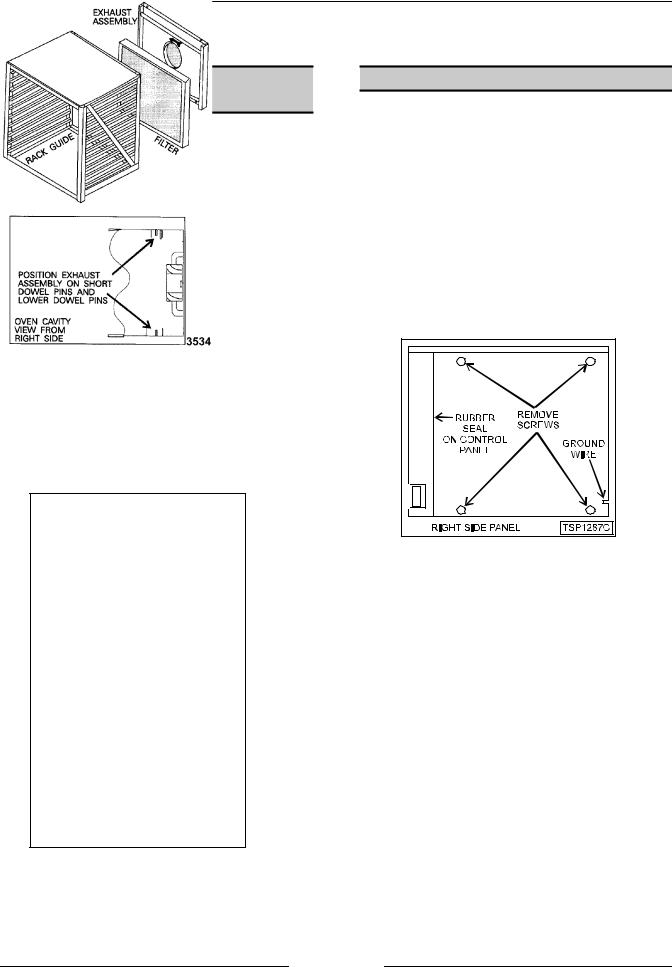
RACK GUIDE/FILTER/EXHAUST
ASSEMBLY
1.Turn the oven off.
2.Remove the racks (if equipped).
3.Push the rack guide to rear of oven to remove the rack guide tabs from slots in the exhaust assembly (10 level).
4.Lift the rear of the rack guide up and pull the guide out of the oven cavity.
5.Lift the filter up, then pull forward to remove the filter (2 filters on 20 level).
WARNING: DISCONNECT THE ELECTRICAL POWER TO THE MACHINE AT THE MAIN CIRCUIT BOX. PLACE A TAG ON THE CIRCUIT BOX INDICATING THE CIRCUIT IS BEING SERVICED.
6.Lift up on exhaust assembly then pull forward at bottom to clear the dowel pins.
7.After lower dowel pins have been cleared, remove assembly from top pins and remove from oven.
COVERS AND PANELS
WARNING: DISCONNECT THE ELECTRICAL POWER TO THE MACHINE AT THE MAIN CIRCUIT BOX. PLACE A TAG ON THE CIRCUIT BOX INDICATING THE CIRCUIT IS BEING SERVICED.
Side Panels
1.Remove the screws from the side panel for the side in need of access. Hold the panel in place before removing the last screw.
2.Access the inside edge of the panel at the bottom rear corner and disconnect the ground wire (if present).
3.Remove the panel.
NOTE: When re-installing the right side panel, ensure the gasket at the rear of the control panel seals properly against the front edge of the right side panel.
4.Reverse procedure to install.
8.Reverse procedure to install.
NOTE: Be sure the bottom of the exhaust assembly is seated on the dowel pins and fan direction arrow is pointing to left (facing oven).
Page 8 of 68
ELECTRIC COMBI OVEN - REMOVAL AND REPLACEMENT OF PARTS
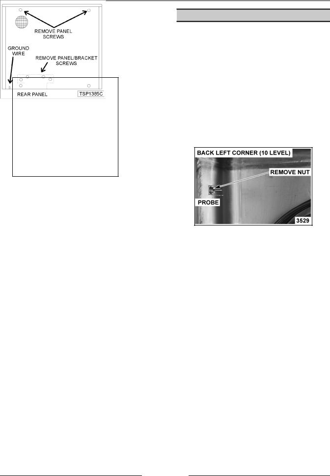
Rear Panel
OVEN TEMPERATURE PROBE
1.Remove the screws from the rear oven panel. Hold the panel in place before removing the last panel screw.
2.Access the inside edge of the panel at the bottom left and disconnect the ground wire (if present).
3.Lower the panel to remove from oven.
4.Reverse procedure to install.
Control Panel
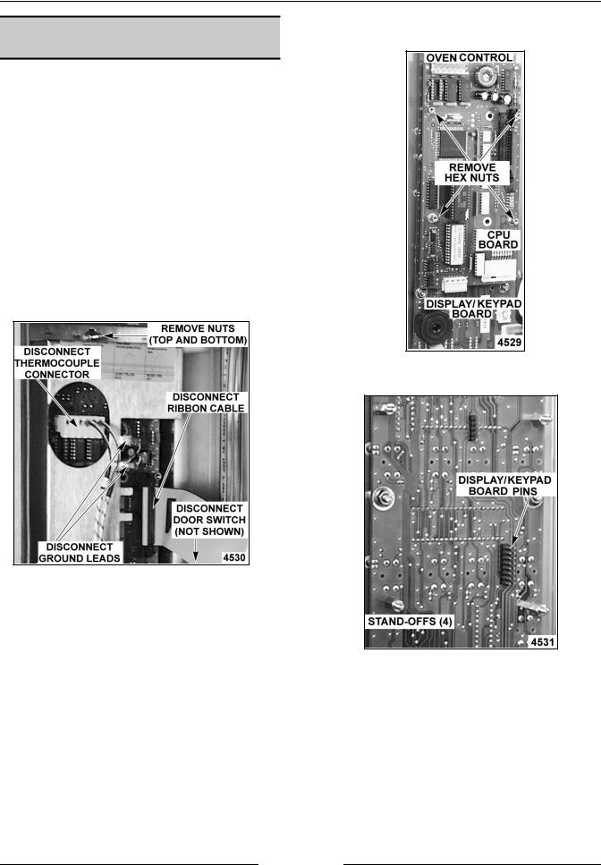
1.Remove the right side panel as outlined.
2.Disconnect the ribbon cable, thermocouple connector, ground leads and door switch connector from the oven control board.
3.Remove the nuts at the top and bottom of control panel that secure it to the frame.
CAUTION: Hold control panel during removal or damage may result to the oven control if dropped.
4.Reverse procedure to install.
WARNING: DISCONNECT THE ELECTRICAL POWER TO THE MACHINE AT THE MAIN CIRCUIT BOX. PLACE A TAG ON THE CIRCUIT BOX INDICATING THE CIRCUIT IS BEING SERVICED.
1.Remove the rack guide, filter and exhaust assembly as outlined under “RACK GUIDE/ FILTER/EXHAUST ASSEMBLY”.
2.Remove both side panels as outlined under “COVERS AND PANELS”.
3.Remove the retaining nut from the probe inside the oven (2 probes on 20 level) and lift bracket off.
4.Remove probe(s) through the left side of the oven cavity.
NOTE: When replacing, use high temperature silicone between the probe and the hole in the oven cavity wall.
NOTE: Be sure to replace bracket around probe and position as shown.
5.Disconnect the probe leads from the control board connector.
6.Reverse procedure to install.
NOTE: When tightening retaining nut, probe will rotate unless secured. Do not clamp down on probe or damage may result.
Page 9 of 68
ELECTRIC COMBI OVEN - REMOVAL AND REPLACEMENT OF PARTS
PROGRAMABLE OVEN
CONTROL
WARNING: DISCONNECT THE ELECTRICAL POWER TO THE MACHINE AT THE MAIN CIRCUIT BOX. PLACE A TAG ON THE CIRCUIT BOX INDICATING THE CIRCUIT IS BEING SERVICED.
CAUTION: Certain components in this system are subject to damage by electrostatic discharge during field repairs. A field service ground kit is available to prevent damage. The field service grounding kit must be used anytime the control board is handled.
1.Remove the right side panel as outlined under “COVERS AND PANELS”.
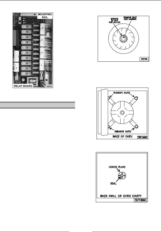
2.Disconnect the ribbon cable, connectors and ground leads from the oven control board.
3.Remove the cover from the oven control by removing the mounting nuts at the top and bottom.
4.Remove the hex nuts securing the CPU board to the display/keypad board.
5.Pull outwards on the CPU board and lift it off from the display/keypad board pin connections.
NOTE: When installing the control board onto the keypad board, make sure that the pins on the keypad board are aligned with the plug on the control board.
Page 10 of 68
ELECTRIC COMBI OVEN - REMOVAL AND REPLACEMENT OF PARTS
6.Remove the display/keypad board from the control panel by removing the mounting nuts.
4.Remove the oven control board from the control panel by removing the mounting nuts.
7.Reverse procedure to install.
5. Reverse procedure to install.
MANUAL OVEN CONTROLS
WARNING: DISCONNECT THE ELECTRICAL POWER TO THE MACHINE AT THE MAIN CIRCUIT BOX. PLACE A TAG ON THE CIRCUIT BOX INDICATING THE CIRCUIT IS BEING SERVICED.
CAUTION: Certain components in this system are subject to damage by electrostatic discharge during field repairs. A field service ground kit is available to prevent damage. The field service grounding kit must be used anytime the control board is handled.
1.Remove the right side panel as outlined under “COVERS AND PANELS”.
2.Disconnect the ribbon cable, thermocouple connector, ground leads and door switch connector from the oven control board.
3.Remove the cover from the oven control board by removing the mounting nuts at the top and bottom.
RELAY BOARD
WARNING: DISCONNECT THE ELECTRICAL POWER TO THE MACHINE AT THE MAIN CIRCUIT BOX. PLACE A TAG ON THE CIRCUIT BOX INDICATING THE CIRCUIT IS BEING SERVICED.
CAUTION: Certain components in this system are subject to damage by electrostatic discharge during field repairs. A field service ground kit is available to prevent damage. The field service grounding kit must be used anytime the control board is handled.
1.Remove the right side panel as outlined under “COVERS AND PANELS”.
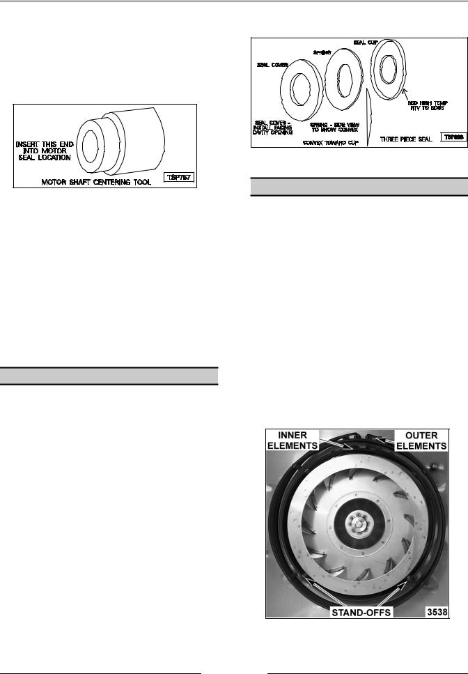
2.Disconnect lead wires from the relay board.
Page 11 of 68
ELECTRIC COMBI OVEN - REMOVAL AND REPLACEMENT OF PARTS
3.Release the clips on the back of the mounting rail.
4.Reverse procedure to install.
BLOWER AND MOTOR
WARNING: DISCONNECT THE ELECTRICAL POWER TO THE MACHINE AT THE MAIN CIRCUIT BOX. PLACE A TAG ON THE CIRCUIT BOX INDICATING THE CIRCUIT IS BEING SERVICED.
Removal
1.Remove the rack guide, filter and exhaust assembly as outlined under “RACK GUIDE/ FILTER/EXHAUST ASSEMBLY”.
2.Loosen bolt (one turn) that secures the blower and install puller.
3.Tighten the puller, then tap the puller with a hammer to loosen the blower from the motor shaft.
4.Remove the puller, bolt, washer and blower from the motor shaft.
NOTE: If only the blower is being removed, reverse the procedure at this point to install.
5.Remove the rear panel as outlined under “COVERS AND PANELS”.
6.Disconnect the lead wires from the motor.
7.Remove the motor from the back of the oven by removing the mounting nuts.
8.Remove the cover plate and seal from inside the oven cavity.
NOTE: You may have to drive the seal out from the back of the oven.
Page 12 of 68
ELECTRIC COMBI OVEN - REMOVAL AND REPLACEMENT OF PARTS
Installation
1.Mount the motor to the back of the oven. Tighten the bolts enough to hold the motor in place, but allow some movement.
2.Ensure that the motor shaft is centered (use shaft centering tool) in the motor shaft hole and tighten mounting bolts.
NOTE: Remove all traces of motor seal grease from the motor shaft.
7.Install the seal cover plate and then the blower.
3.Remove the shaft centering tool.
4.Connect the lead wires to the motor.
5.Install seal and cover as outlined under “BLOWER MOTOR SHAFT SEAL”.
NOTE: Remove all traces of motor seal grease from the motor shaft.
6.Install the blower wheel.
7.Install exhaust assembly, filter, and rack guide as outlined under “RACK GUIDE/FILTER/EXHAUST ASSEMBLY”.
8.Install rear panel as outlined under “COVERS AND PANELS”.
BLOWER MOTOR SHAFT SEAL
WARNING: DISCONNECT THE ELECTRICAL POWER TO THE MACHINE AT THE MAIN CIRCUIT BOX. PLACE A TAG ON THE CIRCUIT BOX INDICATING THE CIRCUIT IS BEING SERVICED.
1.Remove blower as outlined under “BLOWER AND MOTOR”.
2.Remove motor seal cover plate.
3.Remove the seal from the recess in the rear oven wall.
NOTE: You may have to drive the seal out from the back of the oven.
4.Fill replacement seal cover with white silicone grease.
5.Assemble the motor seal with the convex part of the spring toward the motor.
6.Apply red high temperature RTV to the outer edge of the seal to help hold it in the recess and install the seal with the seal cover toward the front of the oven cavity.
HEATING ELEMENTS
WARNING: DISCONNECT THE ELECTRICAL POWER TO THE MACHINE AT THE MAIN CIRCUIT BOX. PLACE A TAG ON THE CIRCUIT BOX INDICATING THE CIRCUIT IS BEING SERVICED.
Oven Cavity
1.Remove the rack guide, filter and exhaust assembly as outlined under “RACK GUIDE/ FILTER/EXHAUST ASSEMBLY”.
2.From inside the oven cavity, remove the nuts from the heating element stand-offs for the element being replaced.
3.Remove the rear panel as outlined under “COVERS AND PANELS”.
4.Disconnect the lead wires from the elements at the rear of the oven.
5.Remove the nuts and washers from the element being replaced then remove the element.
6.Reverse procedure to install.
Page 13 of 68
ELECTRIC COMBI OVEN - REMOVAL AND REPLACEMENT OF PARTS
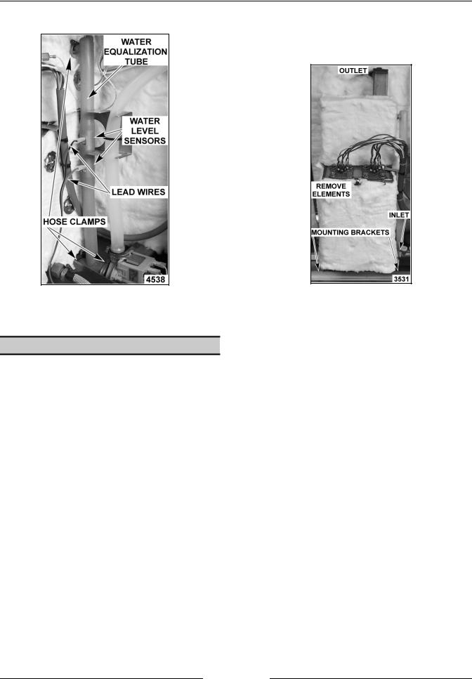
Steam Generator
1.Turn off the water supply to the steam generator.
2.Remove the right side panel as outlined under “COVERS AND PANELS”.
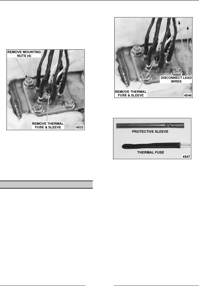
3.Remove the thermal fuse and protective sleeve from the heater thermowell.
4.Disconnect the heating element lead wire connections.
5.Remove the heating element from the steam generator by removing the mounting nuts.
NOTE: When installing a new heater, use the supplied gasket and ensure the mating surfaces are clean.
6.Reverse procedure to install.
THERMAL FUSE(S)
2.Disconnect the thermal fuse(s) lead wire connections.
3.Remove the thermal fuse and protective sleeve from the heater thermowell.
4.Reverse procedure to install.
NOTE: When replacing thermal fuse, be sure to insert the protective sleeve and thermal fuse together. The protective sleeve must be inserted into the heater thermowell with the fuse to avoid chafing of the fuse leads.
WARNING: DISCONNECT THE ELECTRICAL POWER TO THE MACHINE AT THE MAIN CIRCUIT BOX. PLACE A TAG ON THE CIRCUIT BOX INDICATING THE CIRCUIT IS BEING SERVICED.
1.Remove the right side panel as outlined under “COVERS AND PANELS”.
NOTE: When replacing thermal fuse do not pull the lead wires apart. This may break the contact junction or damage the connections.
Page 14 of 68
ELECTRIC COMBI OVEN - REMOVAL AND REPLACEMENT OF PARTS
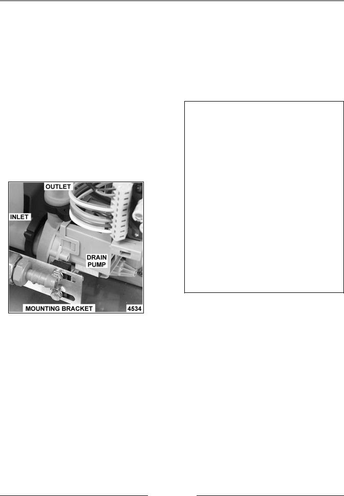
STEAM GENERATOR DRAIN |
|
VENT DAMPER ASSEMBLY |
PUMP |
|
|
1.Turn off the oven and allow the steam generator to drain.
WARNING: DISCONNECT THE ELECTRICAL POWER TO THE MACHINE AT THE MAIN CIRCUIT BOX. PLACE A TAG ON THE CIRCUIT BOX INDICATING THE CIRCUIT IS BEING SERVICED.
2.Turn off the water supply.
3.Remove the right side panel as outlined under “COVERS AND PANELS”.
4.Disconnect lead wires and hoses connected to the drain pump.
5.Remove the bolts from the mounting bracket that secure the pump.
6.Reverse procedure to install.
WARNING: DISCONNECT THE ELECTRICAL POWER TO THE MACHINE AT THE MAIN CIRCUIT BOX. PLACE A TAG ON THE CIRCUIT BOX INDICATING THE CIRCUIT IS BEING SERVICED.
VENT DAMPER ASSEMBLY DIAGRAM
Vent Motor
1.Remove the right side panel as outlined under “COVERS AND PANELS”.
2.Disconnect the lead wires from the switch and motor.
3.Remove the screw and nut behind the motor assembly that connects motor to shaft extension rod.
4.Remove the motor and switch assembly from the oven by sliding the mounting bracket out from the oven frame.
5.Reverse procedure to install.
Page 15 of 68

ELECTRIC COMBI OVEN - REMOVAL AND REPLACEMENT OF PARTS
Sealing Washer
1.Remove the right side panel as outlined under “COVERS AND PANELS”.
2.Open the oven door and remove the rack guide, filter and exhaust assembly as outlined under “RACK GUIDE/FILTER/EXHAUST ASSEMBLY”.
WARNING: THE FOLLOWING STEPS REQUIRE POWER TO BE APPLIED TO THE UNIT DURING THE ADJUSTMENT. USE EXTREME CAUTION AT ALL TIMES.
3.Reconnect the electrical power to the machine at the main circuit box.
4.Close the door, turn the oven ON and press the Start/Stop button.
5.Observe the rotation of the vent motor cam. When the cam stops turning then the vent should be closed.
NOTE: When the oven is turned OFF or the door is opened, the vent should open automatically.
6.Disconnect the electrical power to the machine at the main circuit box. Place a tag on the circuit box indicating the circuit is being serviced.
NOTE: Power to the oven must be removed in this manner. If the oven is turned OFF or the door is opened, the vent will re-open automatically.
7.Open the oven door and examine the vent from inside the cavity.
A.If the mounting nut is visible, proceed to step 8.
B.If the mounting nut is not visible, then the vent needs to rotate 180 degrees. Reconnect power to the machine and repeat steps 3 through 7A.
8.Remove the nut securing both shutters and the sealing washer to the shaft extension rod then remove the shutters and sealing washer.
9.Install new sealing washer and re-assemble.
Shaft Extension
1.Remove the left, right and rear panels as outlined under “COVERS AND PANELS”.
2.Open the oven door and remove the rack guide, filter and exhaust assembly as outlined under “RACK GUIDE/FILTER/EXHAUST ASSEMBLY”.
3.Remove the screw and nut behind the motor assembly that connects motor to shaft extension rod.
4.Rotate the extension rod approximately 90 degrees by hand.
5.Examine the vent from inside the cavity.
A.If the mounting nut is visible, proceed to step 6.
B.If the mounting nut is not visible, then the extension rod needs to rotate approximately 90 degrees more.
6.Remove the nut securing both shutters and the sealing washer to the extension rod then remove the shutters and sealing washer.
7.Remove the shutter screw from the extension rod.
8.Release the snap ring on the left end of the shaft (if facing oven) and pull shaft extension out.
NOTE: If the washers on the exterior of the vent housing come loose, red silicone must be re-applied to prevent steam leakage above the oven cavity.
9.Reverse procedure to install.
WATER LEVEL SENSORS AND WATER EQUALIZATION TUBE
1.Turn the oven off and allow steam generator tank to drain.
WARNING: DISCONNECT THE ELECTRICAL POWER TO THE MACHINE AT THE MAIN CIRCUIT BOX. PLACE A TAG ON THE CIRCUIT BOX INDICATING THE CIRCUIT IS BEING SERVICED.
2.Turn off the water supply.
3.Remove the right side panel as outlined under ”COVERS AND PANELS”.
4.Disconnect lead wires and hose clamps from the water equalization tube.
NOTE: Some water will continue to drain out.
Page 16 of 68
ELECTRIC COMBI OVEN - REMOVAL AND REPLACEMENT OF PARTS
5.Remove the water equalization tube.
6.Reverse procedure to install.
STEAM GENERATOR TANK
1.Turn the oven off and allow the steam generator tank to drain.
WARNING: DISCONNECT THE ELECTRICAL POWER TO THE MACHINE AT THE MAIN CIRCUIT BOX. PLACE A TAG ON THE CIRCUIT BOX INDICATING THE CIRCUIT IS BEING SERVICED.
2.Turn off the water supply to the steam generator
3.Remove the right side and rear panels as outlined under “COVERS AND PANELS”.
4.Disconnect water and steam equalization tube from the steam generator. If necessary, loosen or remove drain pump mounting nuts to remove tube.
10 LEVEL SHOWN
A.Remove heating elements from steam generator tank and place to the side.
NOTE: Unless replacing the heating element(s), it not necessary to remove the heating element lead wires.
B.On 6 and 10 levels, remove clamp from the steam exhaust hose at the top of steam generator and disconnect hose. On 20 levels, remove the nuts securing the steam exhaust pipe to the outside of the cavity.
NOTE: When replacing tank on 20 levels, be sure to seal the mating surface between the exhaust pipe and cavity wall with RTV.
5.Remove the nuts from the tank mounting studs and bracket (at bottom) then remove the steam generator from the oven.
6.Remove insulation from the old steam generator and use on the replacement steam generator.
7.Reverse procedure to install.
Page 17 of 68
ELECTRIC COMBI OVEN - REMOVAL AND REPLACEMENT OF PARTS
OVEN DOOR
WARNING: DISCONNECT THE ELECTRICAL POWER TO THE MACHINE AT THE MAIN CIRCUIT BOX. PLACE A TAG ON THE CIRCUIT BOX INDICATING THE CIRCUIT IS BEING SERVICED.
Removal
1.Remove the left and right side panels as outlined under “COVERS AND PANELS”.
2.Disconnect the lead wires to the lamp on the power supply board terminal block and route them so they can be pulled through the hole in the frame when the door is removed.
3.Support the door, remove the screws from each hinge block on the oven and remove door.
4.Reverse procedure to install.
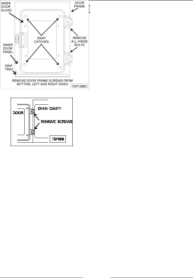
Disassembly
1.Remove the door from the oven as outlined above in “REMOVAL”.
2.Lay the door on a flat surface with the inside of the door facing up.
3.Lift up along the inner door glass edge near the door latch and unsnap the glass from the “snap catches” in the oven door.
4.Open the inner door glass and remove the c- ring clamps from the rear snap catches, unsnap at the rear then lift off.
CAUTION: When replacing the inner door glass, it must be installed with the conductive side toward the front of the oven. Use an ohmmeter to verify the conductive side. Set the meter to read ohms and touch glass with the meter leads. A resistance will be measured but will vary depending on the distance between the meter leads, grease and/or other substances on the glass.
5.Remove the bolts securing the top and bottom hinges to the door.
6.Remove the drip tray, remaining screws from the inner door panel, the screws at the left, right and bottom of the door and remove the door handle.
7.Lift the inner door panel from the outer door frame.
8.Remove the outer door glass.
9.Reverse procedure to install.
10.Adjust the door as outlined under “OVEN DOOR ADJUSTMENT” in “SERVICE PROCEDURES AND ADJUSTMENTS”.
Page 18 of 68
ELECTRIC COMBI OVEN - REMOVAL AND REPLACEMENT OF PARTS
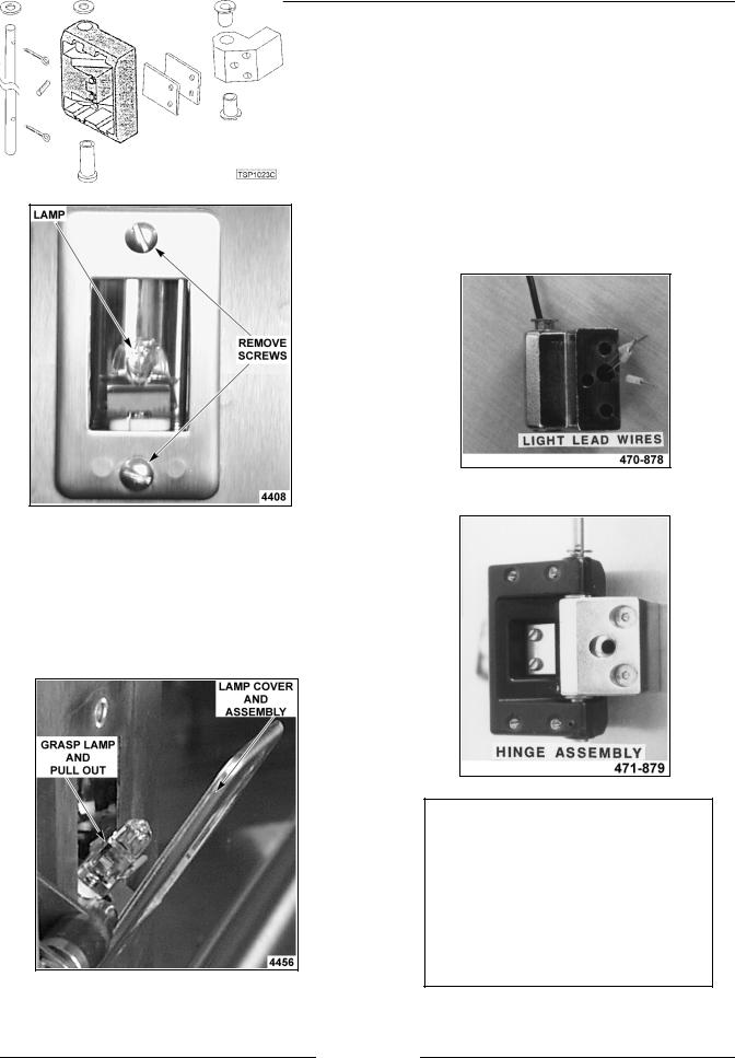
DOOR LAMP |
|
OVEN DOOR HINGES |
WARNING: DISCONNECT THE ELECTRICAL POWER TO THE MACHINE AT THE MAIN CIRCUIT BOX. PLACE A TAG ON THE CIRCUIT BOX INDICATING THE CIRCUIT IS BEING SERVICED.
1.Remove the screws holding the cover and gasket.
2.Pull the lamp and socket assembly out from the door.
3.Hold the lamp assembly and grasp the bulb using a cloth.
NOTE: Do not touch the Halogen lamp with bare hands. If lamp is exposed to oil from the skin, the life will be reduced. Ensure lamp is free from oil and dirt before replacing.
WARNING: DISCONNECT THE ELECTRICAL POWER TO THE MACHINE AT THE MAIN CIRCUIT BOX. PLACE A TAG ON THE CIRCUIT BOX INDICATING THE CIRCUIT IS BEING SERVICED.
1.Remove and disassemble the door as outlined under “OVEN DOOR”.
2.Remove the light lead wire from the hinge.
NOTE: Strip 3 inches of the shielding away from the wires at the terminal end to allow the terminals to be fed through the hinge one at a time.
3.Remove the cotter pins from the shaft and remove the shaft from the hinges.
4.Pull up on light bulb to remove it from socket.
5.Reverse procedure to install.
4.Reverse procedure to install.
Page 19 of 68
ELECTRIC COMBI OVEN - REMOVAL AND REPLACEMENT OF PARTS
DOOR MAGNETIC REED SWITCH
WARNING: DISCONNECT THE ELECTRICAL POWER TO THE MACHINE AT THE MAIN CIRCUIT BOX. PLACE A TAG ON THE CIRCUIT BOX INDICATING THE CIRCUIT IS BEING SERVICED.
1.Remove the right side panel as outlined under “COVERS AND PANELS”.
2.Remove the nuts that secure the door switch mounting bracket to the bottom of the control panel. On 20 levels, the switch is mounted to the underside of the channel for the door handle (no bracket required).
3.Disconnect the switch lead wires.
4.Remove the switch from the oven.
6 AND 10 LEVELS
5.Reverse procedure to install and check for proper operation.
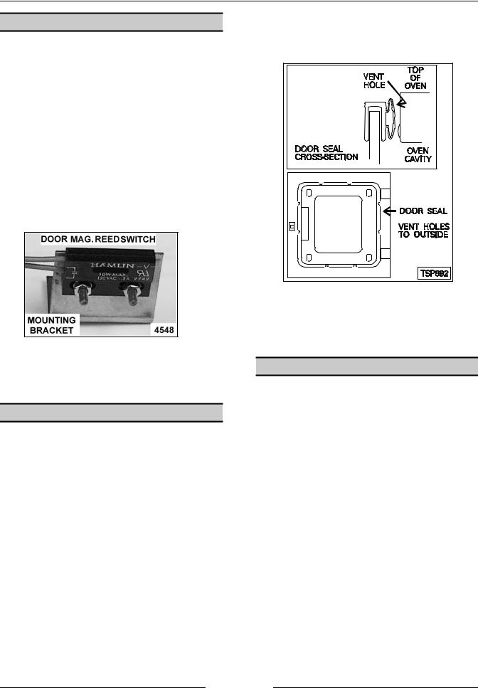
DOOR SEAL
1.Turn the oven off.
2.Open the oven door.
3.Remove seal from the edge of the inside glass.
4.Clean the edge of the glass, remove the old adhesive.
5.Apply red silicone to the replacement seal and install the seal to the glass edge. The vent holes must be installed to the outside to allow the seal to contract when the door is closed.
6.Adjust door closure, if necessary, as outlined under “OVEN DOOR AND DOOR LOCK ADJUSTMENT” in “SERVICE PROCEDURES AND ADJUSTMENTS”.
DOOR LOCKING MECHANISM
WARNING: DISCONNECT THE ELECTRICAL POWER TO THE MACHINE AT THE MAIN CIRCUIT BOX. PLACE A TAG ON THE CIRCUIT BOX INDICATING THE CIRCUIT IS BEING SERVICED.
Replacement
1.Remove the right side panel as outlined under “COVERS AND PANELS”.
2.Disconnect the lead wires to the motor and switches.
3.Remove the nuts from the mounting studs and remove the assembly from the oven.
Page 20 of 68
ELECTRIC COMBI OVEN - REMOVAL AND REPLACEMENT OF PARTS
4.Remove the spring and positioning plate from the locking arm.
5.Reverse procedure to install and adjust as outlined under “OVEN DOOR ADJUSTMENT” in “SERVICE PROCEDURES AND ADJUSTMENTS”.
Disassembly
1.Remove the three screws that secure the motor and switch assembly.
2.Remove the motor, gear box and switch assembly from the locking mechanism. Remove the two bolts from the locking mechanism. The springs, locking arm and bushings can be removed.
4.The springs, locking arm and bushings can be removed.
5.Reverse procedure to install.
OVEN CAVITY SEAL
1.Open the door.
2.Pull the seal from the groove around the oven cavity.
3.Push the arrow head tip of the gasket into the groove. Install the four corners first.
4.Start at the corners and work to the middle of each side, being careful not to stretch the replacement gasket.
5. Check the door for proper operation and adjust if necessary, as outlined under “OVEN DOOR AND DOOR LOCK ADJUSTMENT” in “SERVICE PROCEDURES AND ADJUSTMENTS”.
3.Remove the two bolts from the locking mechanism.
Page 21 of 68
 Loading...