


Vulcan-Hart VC6ED, VC4ES, VC4ED, VC6EC, VCIEC User Manual
...SERVICE MANUAL
|
VC4E & VC6E |
|
|
SERIES |
|
|
FULL SIZE |
|
|
ELECTRIC CONVECTION |
|
|
OVENS |
|
|
MODEL |
ML |
|
VC4ES |
126743 |
|
VC4ED |
126744 |
|
VC4EC |
126745 |
|
VC6ES |
126746 |
VC4ED SHOWN |
VC6ED |
126747 |
|
VC6EC |
126748 |
- NOTICE -
This Manual is prepared for the use of trained Vulcan Service Technicians and should not be used by those not properly qualified. If you have attended a Vulcan Service School for this product, you may be qualified to perform all the procedures described in this manual.
This manual is not intended to be all encompassing. If you have not attended a Vulcan Service School for this product, you should read, in its entirety, the repair procedure you wish to perform to determine if you have the necessary tools, instruments and skills required to perform the procedure. Procedures for which you do not have the necessary tools, instruments and skills should be performed by a trained Vulcan Service Technician.
Reproduction or other use of this Manual, without the express written consent of Vulcan, is prohibited.
A product of VULCAN-HART |
LOUISVILLE, KY 40201-0696 |
|
F25105 (December 2001) |

FULL SIZE ELECTRIC CONVECTION OVENS |
|
TABLE OF CONTENTS |
|
GENERAL . . . . . . . . . . . . . . . . . . . . . . . . . . . . . . . . . . . . . . . . . . . . . . . . . . . . . . . . . . . . . . . . . . . . . . . . . . . . . |
4 |
Introduction . . . . . . . . . . . . . . . . . . . . . . . . . . . . . . . . . . . . . . . . . . . . . . . . . . . . . . . . . . . . . . . . . . . . . . . . |
4 |
Installation . . . . . . . . . . . . . . . . . . . . . . . . . . . . . . . . . . . . . . . . . . . . . . . . . . . . . . . . . . . . . . . . . . . . . . . . . |
4 |
Operation . . . . . . . . . . . . . . . . . . . . . . . . . . . . . . . . . . . . . . . . . . . . . . . . . . . . . . . . . . . . . . . . . . . . . . . . . . |
4 |
Cleaning . . . . . . . . . . . . . . . . . . . . . . . . . . . . . . . . . . . . . . . . . . . . . . . . . . . . . . . . . . . . . . . . . . . . . . . . . . |
4 |
Lubrication . . . . . . . . . . . . . . . . . . . . . . . . . . . . . . . . . . . . . . . . . . . . . . . . . . . . . . . . . . . . . . . . . . . . . . . . . |
4 |
Tools . . . . . . . . . . . . . . . . . . . . . . . . . . . . . . . . . . . . . . . . . . . . . . . . . . . . . . . . . . . . . . . . . . . . . . . . . . . . . |
4 |
Specifications . . . . . . . . . . . . . . . . . . . . . . . . . . . . . . . . . . . . . . . . . . . . . . . . . . . . . . . . . . . . . . . . . . . . . . |
5 |
REMOVAL AND REPLACEMENT OF PARTS . . . . . . . . . . . . . . . . . . . . . . . . . . . . . . . . . . . . . . . . . . . . . . . . . |
6 |
Covers And Panels . . . . . . . . . . . . . . . . . . . . . . . . . . . . . . . . . . . . . . . . . . . . . . . . . . . . . . . . . . . . . . . . . . |
6 |
Control Panel Components . . . . . . . . . . . . . . . . . . . . . . . . . . . . . . . . . . . . . . . . . . . . . . . . . . . . . . . . . . . . |
7 |
Component Panel Components . . . . . . . . . . . . . . . . . . . . . . . . . . . . . . . . . . . . . . . . . . . . . . . . . . . . . . . . . |
8 |
Temperature Probe (Solid State Control) . . . . . . . . . . . . . . . . . . . . . . . . . . . . . . . . . . . . . . . . . . . . . . . . . . |
8 |
Heating Elements . . . . . . . . . . . . . . . . . . . . . . . . . . . . . . . . . . . . . . . . . . . . . . . . . . . . . . . . . . . . . . . . . . . |
9 |
Blower And Motor . . . . . . . . . . . . . . . . . . . . . . . . . . . . . . . . . . . . . . . . . . . . . . . . . . . . . . . . . . . . . . . . . . |
10 |
Door Switch . . . . . . . . . . . . . . . . . . . . . . . . . . . . . . . . . . . . . . . . . . . . . . . . . . . . . . . . . . . . . . . . . . . . . . . |
11 |
Door Window . . . . . . . . . . . . . . . . . . . . . . . . . . . . . . . . . . . . . . . . . . . . . . . . . . . . . . . . . . . . . . . . . . . . . . |
12 |
Oven Doors and Bearings (Independent Doors) . . . . . . . . . . . . . . . . . . . . . . . . . . . . . . . . . . . . . . . . . . . . |
12 |
Oven Doors (Simultaneous Doors) . . . . . . . . . . . . . . . . . . . . . . . . . . . . . . . . . . . . . . . . . . . . . . . . . . . . . . |
13 |
Door Catch Roller Assembly (Independent Doors) . . . . . . . . . . . . . . . . . . . . . . . . . . . . . . . . . . . . . . . . . . |
14 |
Mechanical (KX) Thermostat . . . . . . . . . . . . . . . . . . . . . . . . . . . . . . . . . . . . . . . . . . . . . . . . . . . . . . . . . . |
14 |
High Limit Thermostat . . . . . . . . . . . . . . . . . . . . . . . . . . . . . . . . . . . . . . . . . . . . . . . . . . . . . . . . . . . . . . . |
15 |
Interior Lights . . . . . . . . . . . . . . . . . . . . . . . . . . . . . . . . . . . . . . . . . . . . . . . . . . . . . . . . . . . . . . . . . . . . . . |
15 |
Cooling Fan . . . . . . . . . . . . . . . . . . . . . . . . . . . . . . . . . . . . . . . . . . . . . . . . . . . . . . . . . . . . . . . . . . . . . . . |
16 |
SERVICE PROCEDURES AND ADJUSTMENTS . . . . . . . . . . . . . . . . . . . . . . . . . . . . . . . . . . . . . . . . . . . . . . 17 Solid State Temperature Control Calibration . . . . . . . . . . . . . . . . . . . . . . . . . . . . . . . . . . . . . . . . . . . . . . 17 Mechanical (KX) Thermostat Calibration . . . . . . . . . . . . . . . . . . . . . . . . . . . . . . . . . . . . . . . . . . . . . . . . . 18 Solid State Temperature Control Test . . . . . . . . . . . . . . . . . . . . . . . . . . . . . . . . . . . . . . . . . . . . . . . . . . . 19 Temperature Probe Test (Solid State Control) . . . . . . . . . . . . . . . . . . . . . . . . . . . . . . . . . . . . . . . . . . . . . 20 Heating Element Test . . . . . . . . . . . . . . . . . . . . . . . . . . . . . . . . . . . . . . . . . . . . . . . . . . . . . . . . . . . . . . . 20 Blower Adjustment . . . . . . . . . . . . . . . . . . . . . . . . . . . . . . . . . . . . . . . . . . . . . . . . . . . . . . . . . . . . . . . . . . 21 Door Adjustment . . . . . . . . . . . . . . . . . . . . . . . . . . . . . . . . . . . . . . . . . . . . . . . . . . . . . . . . . . . . . . . . . . . 22 Door Catch Roller Adjustment (Independent Doors) . . . . . . . . . . . . . . . . . . . . . . . . . . . . . . . . . . . . . . . . . 22 Door Switch Adjustment . . . . . . . . . . . . . . . . . . . . . . . . . . . . . . . . . . . . . . . . . . . . . . . . . . . . . . . . . . . . . . 23 Door Chain Adjustment (Simultaneous Doors) . . . . . . . . . . . . . . . . . . . . . . . . . . . . . . . . . . . . . . . . . . . . . 23 Computer Control . . . . . . . . . . . . . . . . . . . . . . . . . . . . . . . . . . . . . . . . . . . . . . . . . . . . . . . . . . . . . . . . . . 24 Computer Control Temperature Calibration . . . . . . . . . . . . . . . . . . . . . . . . . . . . . . . . . . . . . . . . . . . . . . . 26 Computer Control Operational Test . . . . . . . . . . . . . . . . . . . . . . . . . . . . . . . . . . . . . . . . . . . . . . . . . . . . . 26
ELECTRICAL OPERATION . . . . . . . . . . . . . . . . |
. . . . . . . . . . . . . . . . . . . . . . . . . . . . . . . . . . . . . . . . . . . . . . |
29 |
Component Function . . . . . . . . . . . . . . . . . . |
. . . . . . . . . . . . . . . . . . . . . . . . . . . . . . . . . . . . . . . . . . . . . . |
29 |
Component Location . . . . . . . . . . . . . . . . . . |
. . . . . . . . . . . . . . . . . . . . . . . . . . . . . . . . . . . . . . . . . . . . . . |
30 |
Sequence of Operation . . . . . . . . . . . . . . . . |
. . . . . . . . . . . . . . . . . . . . . . . . . . . . . . . . . . . . . . . . . . . . . . |
34 |
VC4ES, VC6ES with Mechanical KX Thermostat . . . . . . . . . . . . . . . . . . . . . . . . . . . . . . . . . . . . . . . |
34 |
|
VC4ED, VC6ED with Solid State Temperature Control . . . . . . . . . . . . . . . . . . . . . . . . . . . . . . . . . . . |
34 |
|
Timer Cycle, Cooking (KX Thermostat or Solid State Control) . . . . . . . . . . . . . . . . . . . . . . . . . . . . . |
35 |
|
Cool Down Cycle (KX Thermostat or Solid State Control) . . . . . . . . . . . . . . . . . . . . . . . . . . . . . . . . . |
35 |
|
VC4EC, VC6EC (Computer Control) . . |
. . . . . . . . . . . . . . . . . . . . . . . . . . . . . . . . . . . . . . . . . . . . . . |
35 |
Temperature and Time Cycle (Cooking) . . . . . . . . . . . . . . . . . . . . . . . . . . . . . . . . . . . . . . . . . . |
36 |
|
Cook and Hold Cycle . . . . . . . . . . |
. . . . . . . . . . . . . . . . . . . . . . . . . . . . . . . . . . . . . . . . . . . . . . |
36 |
Cool Down Cycle . . . . . . . . . . . . . |
. . . . . . . . . . . . . . . . . . . . . . . . . . . . . . . . . . . . . . . . . . . . . . |
36 |
Schematics . . . . . . . . . . . . . . . . . . . . . . . . . |
. . . . . . . . . . . . . . . . . . . . . . . . . . . . . . . . . . . . . . . . . . . . . . |
37 |
VC4ES, VC6ES with Mechanical (KX) Controls, 208-240V . . . . . . . . . . . . . . . . . . . . . . . . . . . . . . . . |
37 |
|
VC4ES, VC6ES with Mechanical (KX) Controls, 480V . . . . . . . . . . . . . . . . . . . . . . . . . . . . . . . . . . . |
38 |
|
VC4ED, VC6ED with Solid State Temperature Control, 208-240V . . . . . . . . . . . . . . . . . . . . . . . . . . |
39 |
|
VC4ED, VC6ED with Solid State Temperature Control, 480V . . . . . . . . . . . . . . . . . . . . . . . . . . . . . . |
40 |
|
F25105 (December 2001) |
Page 2 of 60 |
|

FULL SIZE ELECTRIC CONVECTION OVENS
VC4EC, VC6EC Computer Control, 208-240V (Roast & Hold Standard) . . . . . . . . . . . . . . . . . . . . . . 41 VC4EC, VC6EC Computer Control, 480V (Roast & Hold Standard) . . . . . . . . . . . . . . . . . . . . . . . . . 42 Wiring Diagrams . . . . . . . . . . . . . . . . . . . . . . . . . . . . . . . . . . . . . . . . . . . . . . . . . . . . . . . . . . . . . . . . . . . 44 VC4ES, VC6ES with Mechanical (KX) Control, 208-240V . . . . . . . . . . . . . . . . . . . . . . . . . . . . . . . . . 44 VC4ES, VC6ES with Mechanical (KX) Control, 480V . . . . . . . . . . . . . . . . . . . . . . . . . . . . . . . . . . . . 46 VC4ED, VC6ED with Solid State Temperature Control, 208-240V . . . . . . . . . . . . . . . . . . . . . . . . . . 48 VC4ED, VC6ED with Solid State Temperature Control, 480V . . . . . . . . . . . . . . . . . . . . . . . . . . . . . . 50 VC4EC, VC6EC Computer Control, 208-240V (Roast & Hold Standard) . . . . . . . . . . . . . . . . . . . . . . 52 VC4EC, VC6EC Computer Control, 480V (Roast & Hold Standard) . . . . . . . . . . . . . . . . . . . . . . . . . 54
TROUBLESHOOTING . . . . . . . . . . . . . . . . . . . . . . . . . . . . . . . . . . . . . . . . . . . . . . . . . . . . . . . . . . . . . . . . . . 56
All Models . . . . . . . . . . . . . . . . . . . . . . . . . . . . . . . . . . . . . . . . . . . . . . . . . . . . . . . . . . . . . . . . . . . . . . . . 56
Computer Control Models Only . . . . . . . . . . . . . . . . . . . . . . . . . . . . . . . . . . . . . . . . . . . . . . . . . . . . . . . . 57
CONDENSED SPARE PARTS LIST . . . . . . . . . . . . . . . . . . . . . . . . . . . . . . . . . . . . . . . . . . . . . . . . . . . . . . . . 60
© Vulcan 2001
Page 3 of 60 |
|
F25105 (December 2001) |
|
FULL SIZE ELECTRIC CONVECTION OVEN - GENERAL
GENERAL
INTRODUCTION
Procedures in this manual will apply to all models unless specified. Pictures and illustrations can be of any model unless the picture or illustration needs to be model specific.
Models
|
|
|
FEATURES |
|
OPTIONS |
|||
MODEL |
|
|
|
|
|
|
|
|
|
CAVITY |
TEMPERATURE |
DOORS |
|
COOK |
COOK |
COOK & |
|
|
|
DEPTH |
CONTROL |
(50/50) |
|
TIMER |
TIMER |
HOLD |
|
|
|
|
|
|
|
|
|
VC4ES 4 |
|
26.5" |
Mechanical (KX) |
Independent 1, 2 |
|
1-Hour Dial |
5-Hour Dial |
N/A |
VC4ED |
|
26.5" |
Solid State |
Independent 1, 3 |
|
1-Hour Dial |
5-Hour Dial |
N/A |
VC4EC |
|
26.5" |
Computer |
Independent 1, 3 |
|
24-Hour Digital |
Built in |
Built in |
VC6ES 4 |
|
30.5" |
Mechanical (KX) |
Independent 1, 2 |
|
1-Hour Dial |
5-Hour Dial |
N/A |
VC6ED |
|
30.5" |
Solid State |
Independent 1, 3 |
|
1-Hour Dial |
5-Hour Dial |
N/A |
VC6EC |
|
30.5" |
Computer |
Independent 1, 3 |
|
24-Hour Digital |
Built in |
Built in |
NOTES: |
1. |
Simultaneous doors are optional (with or w/o window). |
|
|
||||
|
2. |
Stainless steel doors w/o window (standard). |
|
|
|
|||
|
3. |
Stainless steel doors with window (standard) |
|
|
|
|||
|
4. |
In February 2001, this model was discontinued. |
|
|
|
|||
|
|
|
|
|
|
|
|
|
INSTALLATION
Refer to the Instructions Manual for detailed installation instructions on single or stacked ovens.
OPERATION
Refer to the Instructions Manual for specific operating instructions.
CLEANING
Refer to the Instructions Manual for specific cleaning instructions.
LUBRICATION
Cavity blower motor has sealed bearings and requires no additional lubrication.
Huskey’s TF1000 grease or equivalent high temperature Teflon grease.
TOOLS
Standard
Standard set of hand tools
VOM with A.C. current tester (Any quality VOM with a sensitivity of at least 20,000 ohms per volt can be used)
Gear Puller to remove blower
Temperature tester (thermocouple type)
Special
Manometer
Clamp on amp meter
Spring force gauge, pull type with a minimum 30 pound full scale range (purchase locally)
RTV sealant, 736 DOW silicone high temp (P/N 542133) or equivalent
F25105 (December 2001) |
|
Page 4 of 60 |
|

FULL SIZE ELECTRIC CONVECTION OVEN - GENERAL
SPECIFICATIONS
Electrical
|
|
|
AMPERAGE - 3 PHASE/ 60HZ |
|
|||||
|
TOTAL |
|
|
|
|
|
|
||
|
PER LINE 1 |
RECOMMENDED |
|||||||
MODEL |
POWER |
|
CIRCUIT |
|
|||||
|
(KW) |
|
|
|
PROTECTION 2 |
||||
|
|
|
|
|
|
|
|
|
|
|
|
208V |
240V |
480V |
208V |
|
240V |
|
480V |
|
|
|
|
|
|
|
|
|
|
VC4ES |
|
|
|
|
|
|
|
|
|
VC4ED |
|
|
|
|
|
|
|
|
|
VC4EC |
12.5 |
35 |
33 |
15 |
45 |
|
40 |
|
20 |
VC6ES |
|
|
|||||||
|
|
|
|
|
|
|
|
|
|
VC6ED |
|
|
|
|
|
|
|
|
|
VC6EC |
|
|
|
|
|
|
|
|
|
|
|
|
|
|
|
|
|
|
|
NOTES: |
1. Amperage values in the table are nominal. |
|
|||||||
|
Tolerance is +5/-10%. |
|
|
|
|
|
|
||
|
2. Complied in accordance with National Electric Code, |
||||||||
|
ANSI/NFPA 70, latest edition. |
|
|
|
|
|
|||
|
|
|
|
|
|
|
|
|
|
|
|
|
|
|
|||||
|
|
|
AMPERAGE - 1 PHASE/ 60HZ |
|
|||||
|
|
|
|
|
|
||||
|
TOTAL |
PER LINE 1 |
RECOMMENDED |
||||||
MODEL |
POWER |
|
CIRCUIT |
|
|||||
|
(KW) |
|
|
|
PROTECTION 2 |
||||
|
|
|
|
|
|
|
|
|
|
|
|
208V |
240V |
480V |
208V |
|
240V |
|
480V |
|
|
|
|
|
|
|
|
|
|
VC4ES |
|
|
|
|
|
|
|
|
|
VC4ED |
|
|
|
|
|
|
|
|
|
VC4EC |
12.5 |
60 |
52 |
26 |
80 |
|
70 |
|
35 |
VC6ES |
|
|
|||||||
|
|
|
|
|
|
|
|
|
|
VC6ED |
|
|
|
|
|
|
|
|
|
VC6EC |
|
|
|
|
|
|
|
|
|
|
|
|
|
|
|
|
|
|
|
NOTES: |
1. Amperage values in the table are nominal. |
|
|||||||
|
Tolerance is +5/-10%. |
|
|
|
|
|
|
||
|
2. Complied in accordance with National Electric Code, |
||||||||
|
ANSI/NFPA 70, latest edition. |
|
|
|
|
|
|||
|
|
|
|
|
|
|
|
|
|
Page 5 of 60 |
|
F25105 (December 2001) |
|
FULL SIZE ELECTRIC CONVECTION OVEN - REMOVAL AND REPLACEMENT OF PARTS
REMOVAL AND REPLACEMENT OF PARTS
COVERS AND PANELS
WARNING: DISCONNECT THE ELECTRICAL POWER TO THE MACHINE AT THE MAIN CIRCUIT BOX. PLACE A TAG ON THE CIRCUIT BOX INDICATING THE CIRCUIT IS BEING SERVICED.
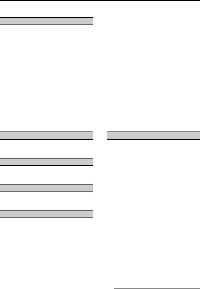
Top Front Cover
1.The top front cover is secured with four (4) screws, two on each side of cover. Remove these screws then remove the cover from the oven.
2.Reverse the procedure to install.
Bottom Front Cover
1.The bottom front cover is secured with four (4) screws, two on each side of cover. Remove these screws then remove the cover from the oven.
2.Reverse the procedure to install.
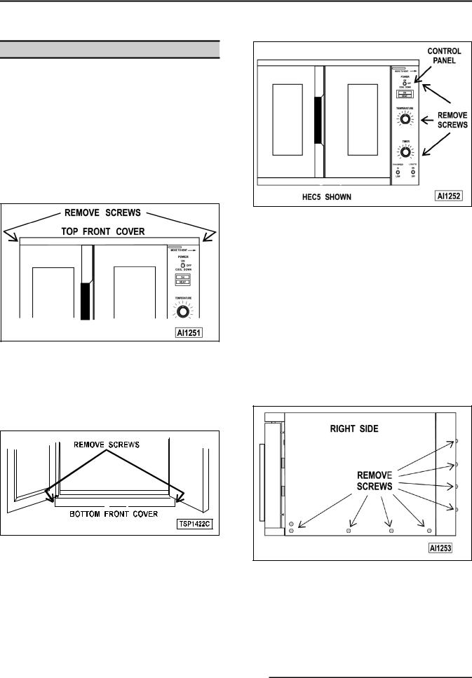
Control Panel
1.Remove three (3) screws on the right side which secure the control panel then pull the panel away from the oven.
NOTE: If the oven has a mechanical (KX type) thermostat, it must be removed from the control panel first, before removing the control panel.
2.Disconnect the temperature probe leads from the solid state temperature control.
3.Unplug the wire harness connector to the control panel components.
4.Reverse the procedure to install.
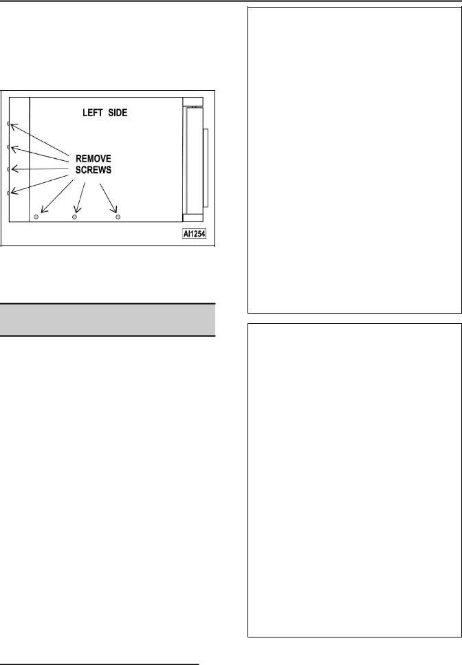
Right Side Panel
1.Remove the two screws near front of oven, which secure the bottom front cover and control panel.
2.Remove the remaining seven screws securing the right side panel.
3.Pull the right side panel out at the bottom then down to remove.
4.Reverse the procedure to install.
F25105 (December 2001) |
|
Page 6 of 60 |
|
FULL SIZE ELECTRIC CONVECTION OVEN - REMOVAL AND REPLACEMENT OF PARTS
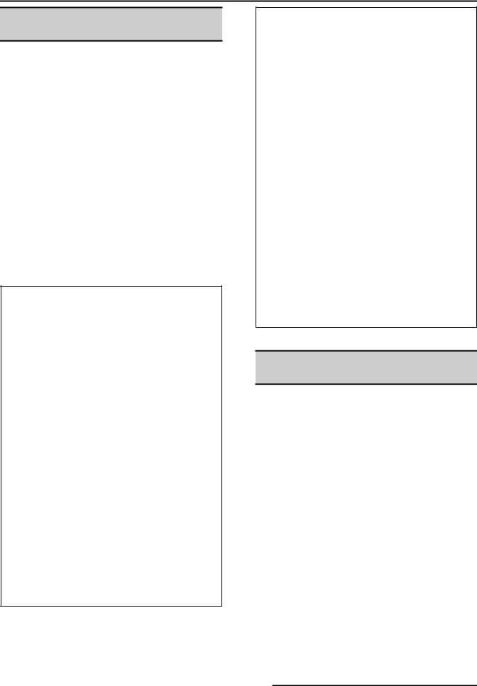
Left Side Panel
1.Remove the screws which secure the left side of the top front cover, bottom front cover and control panel.
2.Remove the seven screws securing the left side panel.
3.Pull the left side panel out at the bottom then down to remove.
4.Reverse the procedure to install.
CONTROL PANEL
COMPONENTS
WARNING: DISCONNECT THE ELECTRICAL
POWER TO THE MACHINE AT THE MAIN
CIRCUIT BOX. PLACE A TAG ON THE CIRCUIT
BOX INDICATING THE CIRCUIT IS BEING
SERVICED.
Removable Components
1.Remove the control panel as outlined under "COVERS AND PANELS".
2.Remove the component being replaced.
3.Reverse the procedure to install the replacement component, then check oven for proper operation.
Page 7 of 60 |
|
F25105 (December 2001) |
|
FULL SIZE ELECTRIC CONVECTION OVEN - REMOVAL AND REPLACEMENT OF PARTS
COMPONENT PANEL
COMPONENTS
WARNING: DISCONNECT THE ELECTRICAL
POWER TO THE MACHINE AT THE MAIN
CIRCUIT BOX. PLACE A TAG ON THE CIRCUIT
BOX INDICATING THE CIRCUIT IS BEING
SERVICED.
Removable Components
1.Remove the right side panel as outlined under "COVERS AND PANELS".
NOTE: If right side panel is not accessible, this component can be serviced by removing the control panel as outlined under "COVERS AND PANELS".
2.Disconnect the wire leads to the component being replaced.
3.Remove the component.
4.Reverse the procedure to install the replacement component and check oven for proper operation.
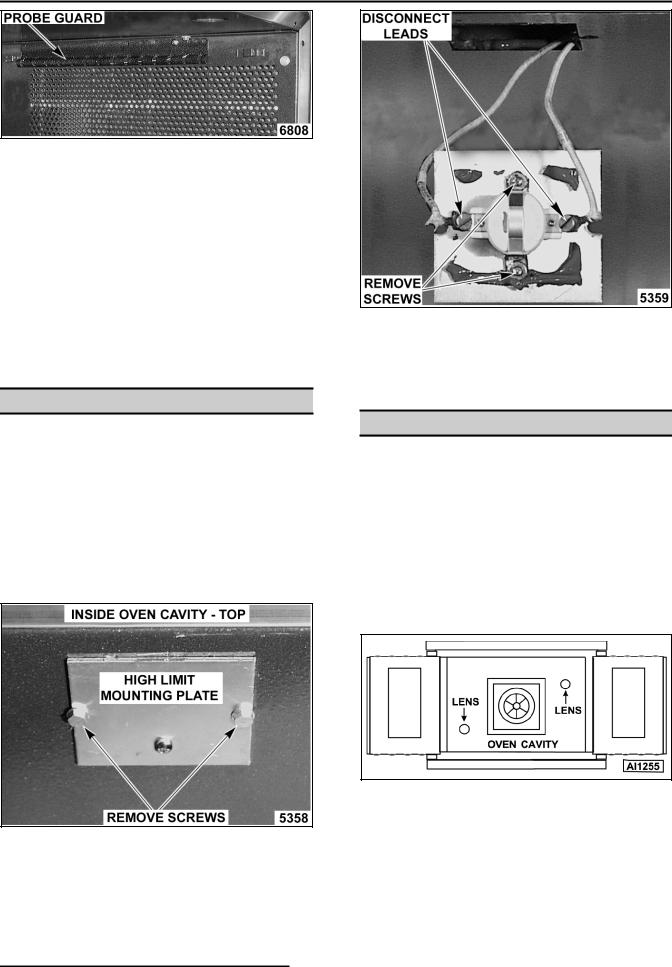
TEMPERATURE PROBE (SOLID STATE CONTROL)
WARNING: DISCONNECT THE ELECTRICAL
POWER TO THE MACHINE AT THE MAIN
CIRCUIT BOX. PLACE A TAG ON THE CIRCUIT
BOX INDICATING THE CIRCUIT IS BEING
SERVICED.
1. Remove the right side panel as outlined under "COVERS AND PANELS".
NOTE: If right side panel is not accessible, this component can be serviced by removing the control panel as outlined under "COVERS AND PANELS".
2. Disconnect the probe leads from the solid state temperature control.
3. Remove the racks and right rack support.
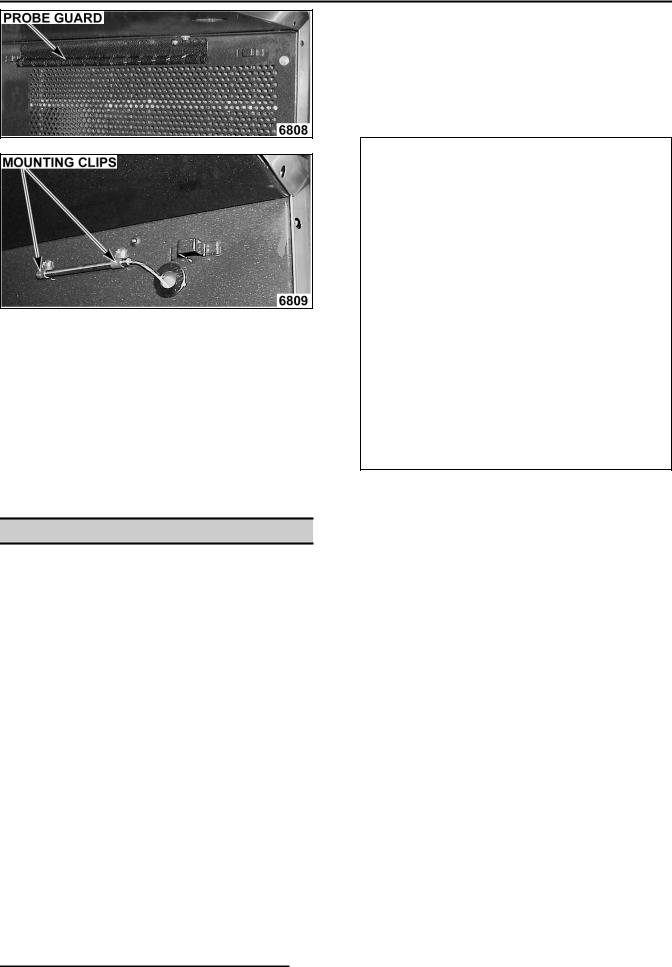
4. Remove the probe guard or mounting clips.
F25105 (December 2001) |
|
Page 8 of 60 |
|
FULL SIZE ELECTRIC CONVECTION OVEN - REMOVAL AND REPLACEMENT OF PARTS
5.Remove probe by pushing it through the oven wall and into the control panel area.
NOTE: The hole in the oven cavity wall does not line up straight with the oven cavity outer shell, therefore the probe must be removed at an angle.
6.Reverse the procedure to install the replacement probe.
7.Adjust the temperature control as outlined under "SOLID STATE TEMPERATURE CONTROL CALIBRATION" in "SERVICE PROCEDURES AND ADJUSTMENTS".
HEATING ELEMENTS
WARNING: DISCONNECT THE ELECTRICAL POWER TO THE MACHINE AT THE MAIN CIRCUIT BOX. PLACE A TAG ON THE CIRCUIT BOX INDICATING THE CIRCUIT IS BEING SERVICED.
NOTE: Starting with production in October, 2001, the top cavity panel will have 3/4" square holes for easier element removal. Ovens manufactured prior to this date have 1/2" round holes that sometimes make it difficult to remove elements thru the cavity. A serial number cut off will not be available. Follow the procedures for element removal as outlined below.
Front Access
1.Remove the oven racks and rack supports.
2.Remove the "top" door seal from the oven.
3.Determine if the heating element to replace is on the left or right side in the oven cavity. The element locations from front to back are: Right side - R1, R2 & R3; Left side - R4, R5 & R6.
A.Measure the current draw of the heating elements as outlined under "HEATING ELEMENT TEST" in "SERVICE PROCEDURES AND ADJUSTMENTS".
4.From inside the oven cavity, remove the perforated panel from the same side of the element being replaced.
A.If removing the right side panel, also remove the probe guard or mounting clips.
B.Run the probe wire thru the panel opening before lifting panel out.
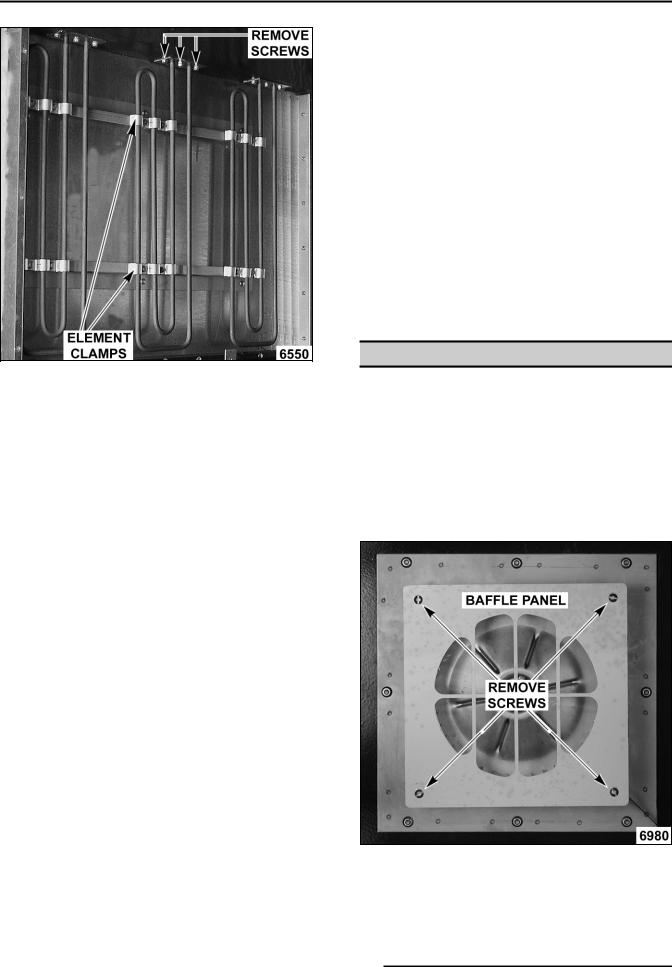
5.From the element being replaced, remove the hold down clamps, the mounting bracket screws at the top, then remove the element.
Page 9 of 60 |
|
F25105 (December 2001) |
|
FULL SIZE ELECTRIC CONVECTION OVEN - REMOVAL AND REPLACEMENT OF PARTS
LEFT SIDE ELEMENTS SHOWN |
3. If the element is on the right side: |
A. Remove the top panel and pull back the insulation to expose the element terminals.
B. Remove the lead wires from the element being replaced.
4. From the same element, remove the two clamps holding the element vertical, the screw’s securing mounting bracket at the top, and then remove the element.
NOTE: The mounting bracket is sealed with RTV which may still hold the element after the screws are removed.
5. Clean RTV residue from the mating surface inside the oven, apply new high temperature RTV to the heating element mounting bracket and reverse procedure to install.
6. Check for proper operation.
BLOWER AND MOTOR
NOTE: The mounting bracket is sealed with RTV which may still hold the element after the screws are removed. Also, in some cases, the ring terminal connected to the element may interfere with easy removal. If access to the left side panel and/or the top panel is available, see "ALTERNATE ACCESS".
6.Disconnect the lead wires from the element.
7.Clean RTV residue from the mating surface inside the oven, apply new high temperature RTV to the heating element mounting bracket and reverse procedure to install.
8.Check for proper operation.
Alternate Access
If the heating element is not removing easily from inside the oven cavity, and access to the left side panel and/or the top panel is available, this alternate removal method may be used.
NOTE: On stacked ovens, if the bottom oven is being serviced and the heating element to replace is on the right side, the ovens must be unstacked to access the heating element terminals through the top. Once unstacked, follow the removal procedure below.
1.Perform steps 1 thru 4 under "FRONT ACCESS".
2.If the element is on the left side:
A.Remove the left side panel and pull back the insulation at the top to expose the element terminals.
B.Remove the lead wires from the element being replaced. Proceed to step 4.
WARNING: DISCONNECT THE ELECTRICAL POWER TO THE MACHINE AT THE MAIN CIRCUIT BOX. PLACE A TAG ON THE CIRCUIT BOX INDICATING THE CIRCUIT IS BEING SERVICED.
1.Take out the racks and rack supports.
2.Remove screws securing baffle panel and remove the panel.
3.If replacing:
A.Blower Only - Loosen set screws on blower hub and using a bearing puller, remove blower from motor shaft.
F25105 (December 2001) |
|
Page 10 of 60 |
|
FULL SIZE ELECTRIC CONVECTION OVEN - REMOVAL AND REPLACEMENT OF PARTS
1)Reverse procedure to install and adjust blower position as outlined under "BLOWER ADJUSTMENT" in "SERVICE PROCEDURES AND ADJUSTMENTS".
B.Motor - perform step 3A and continue procedure.
4.Remove the nuts that secure the motor mounting plate to the rear wall.
10.Reconnect lead wires at the motor, replace conduit and junction box cover.
NOTE: Check data plate on motor for wiring schematic. The motor must rotate clockwise when viewed from the shaft end.
5.Place a piece of cardboard on the bottom of the oven cavity to protect its surface from any damage during motor assembly removal.
6.Pull the motor assembly into the oven cavity and place it on the cardboard.
7.Remove the junction box cover from the motor, disconnect lead wires and remove the conduit.
8.Remove motor mounting bolts and flat washers then lift the motor from the mounting plate.
9.Position the replacement motor on the motor mounting plate and install mounting bolts and washers. Hand tighten mounting bolts only.
11.Slide blower onto motor shaft until hub is flush with end of shaft then tighten set screws.
12.Adjust motor position until blower is parallel to motor mounting plate as outlined under "BLOWER ADJUSTMENT" in "SERVICE PROCEDURES AND ADJUSTMENTS".
13.Position motor mounting plate on the rear wall and secure with nuts and washers.
14.Replace the baffle panel.
15.Remove cardboard from the bottom of the oven cavity.
16.Check oven for proper operation then replace rack guides and racks.
DOOR SWITCH
WARNING: DISCONNECT THE ELECTRICAL POWER TO THE MACHINE AT THE MAIN CIRCUIT BOX. PLACE A TAG ON THE CIRCUIT BOX INDICATING THE CIRCUIT IS BEING SERVICED.
1.Remove the top front cover as outlined under "COVERS AND PANELS".
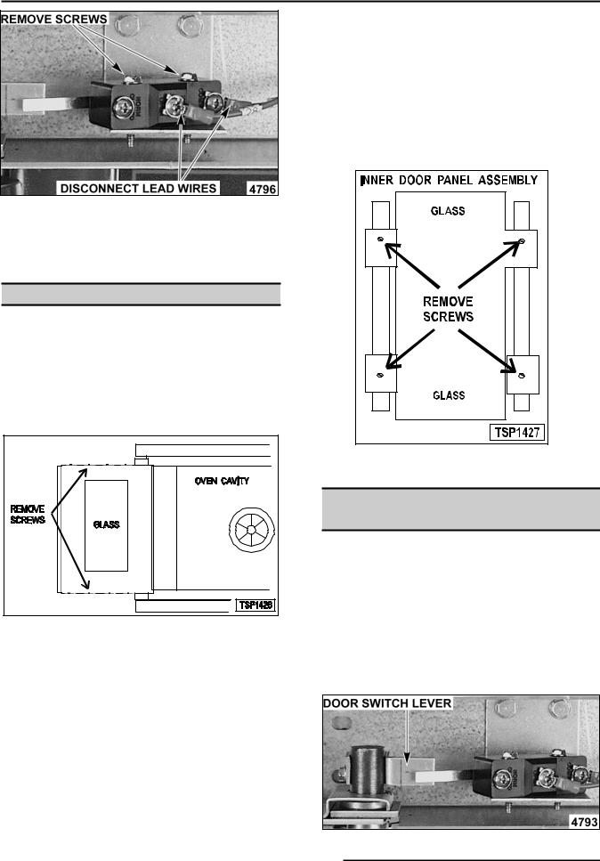
2.Disconnect the lead wires to the door switch.
3.Remove the switch.
Page 11 of 60 |
|
F25105 (December 2001) |
|
FULL SIZE ELECTRIC CONVECTION OVEN - REMOVAL AND REPLACEMENT OF PARTS
4.Reverse procedure to install the replacement switch and check for proper adjustment as outlined under "DOOR SWITCH ADJUSTMENT" in "SERVICE PROCEDURES AND ADJUSTMENTS".
DOOR WINDOW
WARNING: DISCONNECT THE ELECTRICAL POWER TO THE MACHINE AT THE MAIN CIRCUIT BOX. PLACE A TAG ON THE CIRCUIT BOX INDICATING THE CIRCUIT IS BEING SERVICED.
1.Remove the screws at the top and bottom of door.
2.Independent doors:
A.Remove the door handle then remove the outer door panel.
B.Lift out the inner door panel and window assembly.
NOTE: Left door only - remove door seal from the inside edge of the door.
3.Simultaneous doors:
A.If replacing window on the left door, remove the handle from the front of the door then remove door seal from the inside edge of the door.
1)Lift out the inner door panel and window assembly.
2)If replacing window on the right door, remove the screws along the inside edge (if applicable) of the door then remove the inner door panel and window assembly.
4.Remove the screws securing the window “tabs” to the door bracket and lift the window assembly out from the door frame.
5.Reverse procedure to install the replacement window.
OVEN DOORS AND BEARINGS (INDEPENDENT DOORS)
WARNING: DISCONNECT THE ELECTRICAL POWER TO THE MACHINE AT THE MAIN CIRCUIT BOX. PLACE A TAG ON THE CIRCUIT BOX INDICATING THE CIRCUIT IS BEING SERVICED.
1.Remove the top front cover and bottom front cover as outlined under "COVERS AND PANELS".
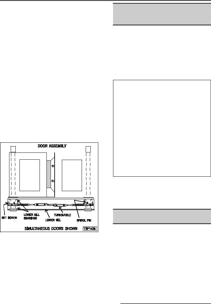
2.Remove the door switch lever.
F25105 (December 2001) |
|
Page 12 of 60 |
|

FULL SIZE ELECTRIC CONVECTION OVEN - REMOVAL AND REPLACEMENT OF PARTS
3.Remove the lower door seal strip to expose the mounting screws of the door assembly.
4.Remove the two (2) lower sill bolts by the lower door shaft and the four (4) counter-sunk screws from the lower sill.
NOTE: The door assembly is heavy and will drop down once the last screw is removed. If removing door assembly with-out assistance, use caution.
5.Tilt the top of the door slightly forward and lift the door up until the bottom of the door shaft clears the opening in the sill.
6.Lay the door flat to prevent damage.
7.The top and bottom bearings are now accessible for inspection and/or replacement if needed.
A.If bearings are ok, proceed to step 8.
B.If replacing the top bearing, remove the top bearing retainer and top bearing.
C.If replacing the bottom bearing, remove it from the door shaft or the lower sill opening.
8.Reverse procedure to install door assembly and check for proper adjustment as outlined under "DOOR ADJUSTMENT" and "DOOR SWITCH ADJUSTMENT" in "SERVICE PROCEDURES AND ADJUSTMENTS".
OVEN DOORS
(SIMULTANEOUS DOORS)
WARNING: DISCONNECT THE ELECTRICAL POWER TO THE MACHINE AT THE MAIN CIRCUIT BOX. PLACE A TAG ON THE CIRCUIT BOX INDICATING THE CIRCUIT IS BEING SERVICED.
Assembly Removal
1.Remove the top front cover and bottom front cover as outlined under "COVERS AND PANELS".
2.Remove the door switch lever.
3.Remove the top bearing retainers and top bearings.
4.Remove the lower door seal strip to expose the mounting screws of the door assembly.
A.Remove the two (2) lower sill bolts by the lower door shaft and the four (4) counter-sunk screws from the lower sill.
NOTE: The door assembly is heavy and will drop down once the last screw is removed. If removing door assembly with-out assistance, use caution.
Page 13 of 60 |
|
F25105 (December 2001) |
|
FULL SIZE ELECTRIC CONVECTION OVEN - REMOVAL AND REPLACEMENT OF PARTS
5.Lift up on the door assembly and swing the right side out then move the assembly to the left to clear the slots in the upper door sill.
6.Lay the door assembly on a flat cushioned surface for disassembly.
7.Reverse procedure to install door assembly and check for proper adjustment as outlined under "DOOR ADJUSTMENT", "DOOR CHAIN ADJUSTMENT (SIMULTANEOUS DOORS)" and "DOOR SWITCH ADJUSTMENT" in "SERVICE PROCEDURES AND ADJUSTMENTS".
Disassembly
1.Remove the door assembly as outlined in "OVEN DOORS (SIMULTANEOUS)" under "ASSEMBLY REMOVAL".
2.Remove the door chain by loosening one of the turnbuckles.
3.Loosen the set screw on the sprocket of door being replaced.
4.Drive out the spirol pin from the sprocket of door being replaced.
5.Remove the door from lower sill bearings and sprocket.
DOOR CATCH ROLLER
ASSEMBLY
(INDEPENDENT DOORS)
WARNING: DISCONNECT THE ELECTRICAL POWER TO THE MACHINE AT THE MAIN CIRCUIT BOX. PLACE A TAG ON THE CIRCUIT BOX INDICATING THE CIRCUIT IS BEING SERVICED.
1.Remove the top front cover as outlined under “COVERS AND PANELS”.
2.Remove the catch roller assembly.
3.Reverse procedure to install.
4.Adjust the catch roller as outlined under “DOOR CATCH (ROLLER) ADJUSTMENT (INDEPENDENT DOORS)” in “SERVICE PROCEDURES AND ADJUSTMENTS”.
MECHANICAL (KX)
THERMOSTAT
A.Door assembly parts are now accessible for inspection and/or replacement if necessary.
6.Reverse procedure to re-assemble the door assembly parts and check for proper adjustment as outlined under "DOOR CHAIN ADJUSTMENT (SIMULTANEOUS DOORS)" in "SERVICE PROCEDURES AND ADJUSTMENTS".
WARNING: DISCONNECT THE ELECTRICAL POWER TO THE MACHINE AT THE MAIN CIRCUIT BOX. PLACE A TAG ON THE CIRCUIT BOX INDICATING THE CIRCUIT IS BEING SERVICED.
1.Remove the racks and right rack support.
2.Remove the thermostat knob and mounting screws from the control panel and then remove the control panel.
3.Remove the probe guard from the oven cavity wall.
F25105 (December 2001) |
|
Page 14 of 60 |
|
FULL SIZE ELECTRIC CONVECTION OVEN - REMOVAL AND REPLACEMENT OF PARTS
NOTE: When installing probe guard, the probe should not extend beyond the guard.
4.Remove the thermostat bulb from the oven cavity by pushing it through the oven wall and into the control panel area.
NOTE: The hole in the oven cavity wall does not line up straight with the oven cavity outer shell, therefore the probe must be removed at an angle.
5.Reverse the procedure to install.
6.Adjust the thermostat as outlined under "MECHANICAL (KX) THERMOSTAT CALIBRATION " in "SERVICE PROCEDURES AND ADJUSTMENTS".
HIGH LIMIT THERMOSTAT
WARNING: DISCONNECT THE ELECTRICAL POWER TO THE MACHINE AT THE MAIN CIRCUIT BOX. PLACE A TAG ON THE CIRCUIT BOX INDICATING THE CIRCUIT IS BEING SERVICED.
1.Take out racks from the oven.
2.Remove the high limit thermostat cover/mounting plate from inside the oven cavity at the top.
3.Disconnect lead wires from high limit thermostat then remove high limit thermostat from cover/mounting plate.
NOTE: Remove the old RTV sealer from the cover and mating surfaces inside the oven cavity and apply new high temperature RTV sealer before installing.
4.Reverse procedure to install.
INTERIOR LIGHTS
WARNING: DISCONNECT THE ELECTRICAL POWER TO THE MACHINE AT THE MAIN CIRCUIT BOX. PLACE A TAG ON THE CIRCUIT BOX INDICATING THE CIRCUIT IS BEING SERVICED.
Lamp
1.Remove the racks.
2.Unscrew the glass lens for the light being replaced then unscrew the bulb.
3.Replace bulb then reverse the procedure to install.
Lamp Assembly
1.Remove the lens and bulb.
2.Remove the springs from the retaining tabs (2 places) on the socket.
Page 15 of 60 |
|
F25105 (December 2001) |
|

FULL SIZE ELECTRIC CONVECTION OVEN - REMOVAL AND REPLACEMENT OF PARTS
3.Depress the retaining tabs and pull the socket out from the oven, far enough to disconnect the lead wires.
4.Remove the socket from the oven.
5.Attach the lead wires to the replacement socket.
6.Insert the socket into the hole in the oven and push until the socket is held in place by the retaining tabs.
7.Install the light bulb and lens.
8.Check for proper operation.
COOLING FAN
WARNING: DISCONNECT THE ELECTRICAL POWER TO THE MACHINE AT THE MAIN CIRCUIT BOX. PLACE A TAG ON THE CIRCUIT BOX INDICATING THE CIRCUIT IS BEING SERVICED.
1.Remove the right side panel as outlined under "COVERS AND PANELS".
NOTE: If right side panel is not accessible, this component can be serviced by removing the control panel as outlined under "COVERS AND PANELS".
2.Disconnect the lead wires to the fan motor by removing wire nuts.
3.Remove the screws securing the air deflector to the fan then loosen the tab screw holding the fan to the component panel. Rotate the tab so that the fan will clear and remove the fan.
4.Reverse the procedure to install the replacement fan and check for proper operation.
NOTE: The fan must be installed so air is pulled from outside the rear of the oven and blown into the control area. The arrow on the fan body indicates “air flow” direction and should be pointing toward the controls.
NOTE: Ensure fan is seated “squarely” against the air tube and the oven bottom.
NOTE: The air deflector should be angled upwards at approximately 30 degrees to properly direct the air flow.
F25105 (December 2001) |
|
Page 16 of 60 |
|
FULL SIZE ELECTRIC CONVECTION OVENS - SERVICE PROCEDURES AND ADJUSTMENTS
SERVICE PROCEDURES AND ADJUSTMENTS
WARNING: CERTAIN PROCEDURES IN THIS SECTION REQUIRE ELECTRICAL TEST OR MEASUREMENTS WHILE POWER IS APPLIED TO THE MACHINE. EXERCISE EXTREME CAUTION AT ALL TIMES. IF TEST POINTS ARE NOT EASILY ACCESSIBLE, DISCONNECT POWER, ATTACH TEST EQUIPMENT AND REAPPLY POWER TO TEST.
SOLID STATE TEMPERATURE CONTROL CALIBRATION
1.Place a thermocouple in the geometric center of the oven cavity.
2.Set the power switch to ON.
3.Set the temperature control dial to 350 °F.
4.Allow the oven temperature to stabilize (normally 3 cycles).
5.Record the temperature at which the Heat lamp goes OFF and comes ON for at least two complete heating cycles.
6.Calculate the differential by subtracting the temperature indicated when the lamp goes out from the temperature indicated when the lamp comes on.
Differential Heat lamp OFF Heat lamp ON Example: 360 (lamp off) 340 (lamp on) 20
A.The differential calculated should be less than 20 °F.
1)If the differential is 20 °F or less, the temperature control circuit is functioning properly.
a.Proceed to step 7.
2)If the differential is more than 20 °F:
a.Check the temperature probe as outlined under "TEMPERATURE PROBE TEST (SOLID STATE CONTROL)".
b.If the probe is functioning properly then temperature control is malfunctioning.
a)Install a replacement temperature control and check calibration.
7.Calculate the average temperature by adding the temperature indicated when the lamp goes out to the temperature indicated when the lamp comes on and dividing this answer by 2.
[Temp. (lamp off) Temp. (lamp on)] ÷ 2 Average Temp.
Example: 360 340 ÷ 2 350
A.If the average temperature is 10 °F or less, from the dial setting, the thermostat is properly calibrated.
B.If the average temperature is more than 10 °F from the dial setting, the thermostat calibration must be adjusted.
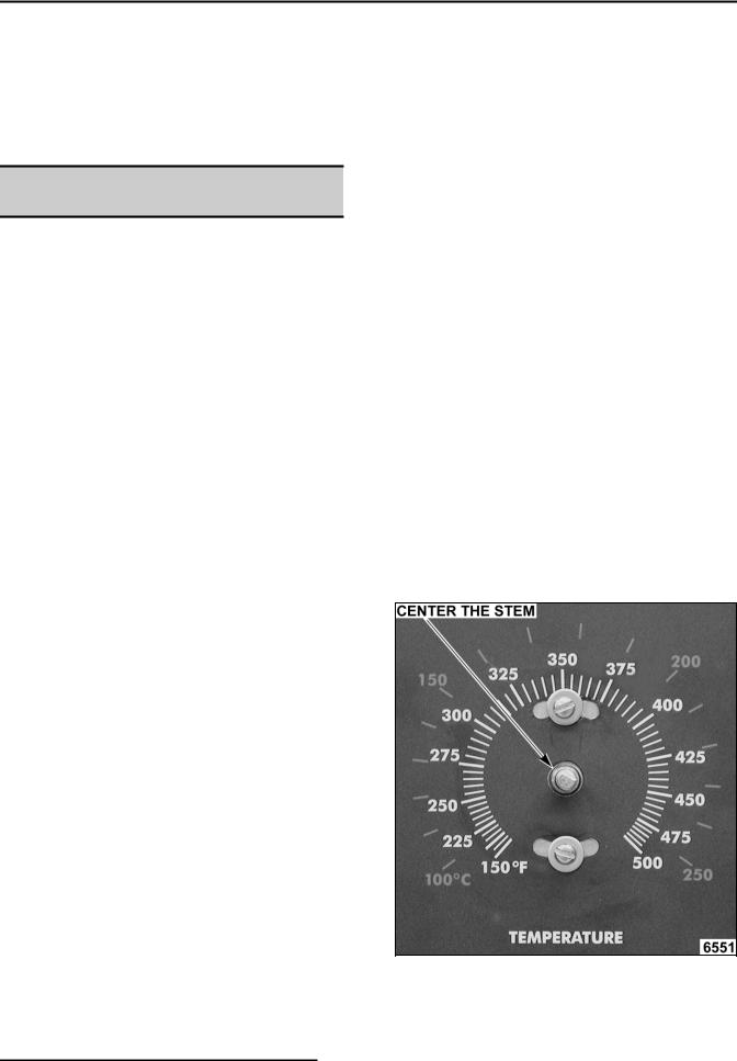
1)Loosen the temperature control knob set screw and remove the knob from the stem.
2)Loosen temperature control mounting screws only enough to rotate the control.
a.Place thumb and forefinger on the head of the mounting screws, apply pressure and slightly rotate the screw heads (body of control) in the slot. Rotate clockwise to increase temperature and counterclockwise to decrease.
b.Center the stem in the opening and re-tighten the temperature control mounting screws.
c.Replace knob and re-tighten set screw .
Page 17 of 60 |
|
F25105 (December 2001) |
|
FULL SIZE ELECTRIC CONVECTION OVENS - SERVICE PROCEDURES AND ADJUSTMENTS
d.Rotate the knob to the lowest temperature setting then back to 350°F.
e.Repeat the average temperature calculation in step 7.
NOTE: Allow the oven to cycle at least two times between adjustments before performing the calculation.
a)If the average temperature still differs more than 10 °F from the dial setting, adjust the thermostat calibration until the average temperature is within tolerance.
C.If the above adjustment cannot be obtained:
1)Turn the power switch OFF.
WARNING: DISCONNECT THE ELECTRICAL POWER TO THE MACHINE AT THE MAIN CIRCUIT BOX. PLACE A TAG ON THE CIRCUIT BOX INDICATING THE CIRCUIT IS BEING SERVICED.
2)Replace the temperature control and check calibration.
MECHANICAL (KX)
THERMOSTAT CALIBRATION
1.Place a thermocouple in the geometric center of the oven cavity.
2.Set the power switch to ON.
3.Set the thermostat dial to 350 °F.
4.Allow the oven temperature to stabilize (normally 3 cycles).
5.Record the temperature when the thermostat cycles OFF and ON for at least three complete cycles.
6.Calculate the differential by subtracting the temperature indicated when heat lamp goes out from temperature indicated when heat lamp comes on.
Differential Heat lamp OFF Heat lamp ON Example: 360 (lamp off) 340 (lamp on) 20
A.The differential calculated should be less than 30 F.
1)If the differential is 30 °F or less, the thermostat is functioning properly.
a. Proceed to step 7.
2)If the differential is more than 30 F, the thermostat is malfunctioning.
a.Install a replacement thermostat and check calibration.
7.Calculate the average temperature by adding the temperature indicated when the heat lamp goes out to the temperature indicated when the heat lamp comes on and dividing this answer by 2.
[Temp. (lamp off) Temp. (lamp on)] ÷ 2 Average Temp.
Example: 360 340 ÷ 2 350
A.If the average temperature is 15 F or less from the dial setting, the thermostat is properly calibrated.
B.If the average temperature is more than 15 F of the dial setting, the thermostat calibration must be adjusted.
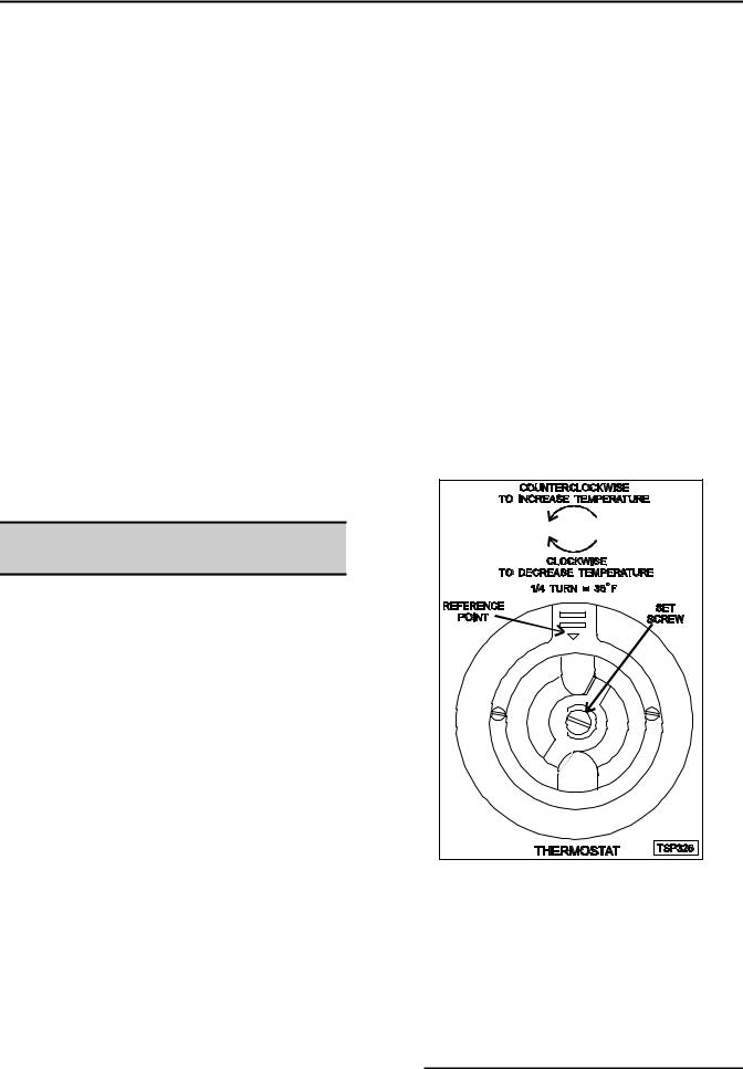
1)Remove the thermostat knob.
2)Hold the thermostat shaft and turn the inner set screw clockwise to decrease temperature or counterclockwise to increase temperature (¼ turn = 35 F).
8.Replace the knob and verify the setting is still at 350°F.
9.Repeat step 7 until the average temperature is within tolerance.
NOTE: Allow the oven to cycle at least two times between adjustments before performing the calculation.
F25105 (December 2001) |
|
Page 18 of 60 |
|
 Loading...