


VC6GC
Vulcan-Hart VC6GC, VC4GC, VC6GD, ML-126611, ML-136495 User Manual
...
INSTALLATION &
OPERATION MANUAL
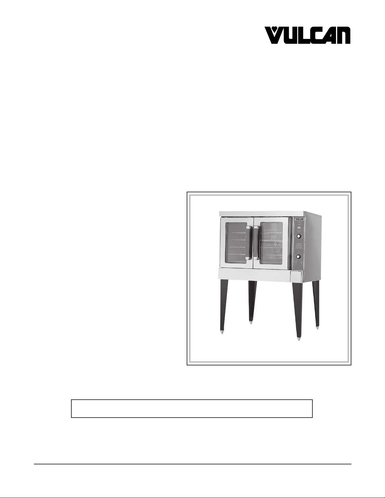
VC SERIES
GAS CONVECTION OVENS
MODELS
VC4GD ML-126611
VC4GC ML-136494
VC6GD ML-126613
VC6GC ML-136495
STACKED MODELS
VC44GD ML-126611
VC44GC ML-136494
VC66GD ML-126613
VC66GC ML-136495
MODEL VC4GD
VULCAN-HART
DIVISION OF ITW FOOD EQUIPMENT GROUP, LLC
WWW.VULCANHART.COM
P.O. BOX 696
LOUISVILLE, KY 40201-0696
FORM 31123 Rev. G (10-06)
For additional information on Vulcan-Hart or to locate an authorized parts
and service provider in your area, visit our website at www.vulcanhart.com
– 2 –
IMPORTANT FOR YOUR SAFETY
THIS MANUAL HAS BEEN PREPARED FOR PERSONNEL QUALIFIED TO INSTALL GAS
EQUIPMENT, WHO SHOULD PERFORM THE INITIAL FIELD START-UP AND
ADJUSTMENTS OF THE EQUIPMENT COVERED BY THIS MANUAL.
POST IN A PROMINENT LOCATION THE INSTRUCTIONS TO BE FOLLOWED IN THE
EVENT THE SMELL OF GAS IS DETECTED. THIS INFORMATION CAN BE OBTAINED
FROM THE LOCAL GAS SUPPLIER.
IMPORTANT
IN THE EVENT A GAS ODOR IS DETECTED, SHUT DOWN
UNITS AT MAIN SHUTOFF VALVE AND CONTACT THE
LOCAL GAS COMPANY OR GAS SUPPLIER FOR
SERVICE.
FOR YOUR SAFETY
DO NOT STORE OR USE GASOLINE OR OTHER
FLAMMABLE VAPORS OR LIQUIDS IN THE VICINITY OF
THIS OR ANY OTHER APPLIANCE.
WARNING: IMPROPER INSTALLATION, ADJUSTMENT,
ALTERATION, SERVICE OR MAINTENANCE CAN CAUSE
PROPERTY DAMAGE, INJURY OR DEATH. READ THE
INSTALLATION, OPERATING AND MAINTENANCE
INSTRUCTIONS THOROUGHLY BEFORE INSTALLING
OR SERVICING THIS EQUIPMENT.
IN THE EVENT OF A POWER FAILURE, DO NOT ATTEMPT
TO OPERATE THIS DEVICE.
© VULCAN-HART, 2005, 2006
– 3 –
Installation, Operation and Care of
VC SERIES
GAS CONVECTION OVENS
KEEP THIS MANUAL FOR FUTURE REFERENCE
GENERAL
Models VC4GD and VC6GD feature a solid state temperature control. Models VC4GC and VC6GC
feature a programmable oven controller. One hour dial timer is standard; five hour timer is optional.
Two-speed
1
/2 HP (0.37 kw) electric motor is standard equipment. Each oven is furnished with 5 racks;
additional oven racks are available. The burner input rating for each oven is 44,000 BTU/hr.
Porcelain interior is standard on all models.
Model VC6GD and VC6GC has a 4 inches (102 mm) deeper oven cavity.
Standard ovens are 120 V, 60 Hz, 1 PH and include cord and plug. Optional electrical specifications
of 208/240 V are available and require hard wire connection.
Independently opening doors are standard; simultaneous door opening is optional.
Other options include: an open stand with lower storage rack, roast and hold, and a stacking kit for
mounting one oven on top of another.
Vulcan VC Series Gas Convection Ovens are produced with quality workmanship and material. Proper
installation, usage and maintenance of your oven will result in many years of satisfactory performance.
It is suggested that you thoroughly read this entire manual and carefully follow all of the instructions
provided.
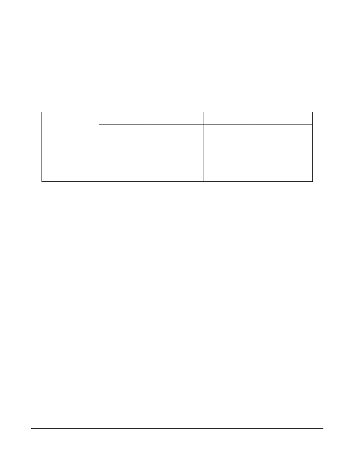
Model Thermostat Timer
Oven Roast &
Legs
Stand with
Voltage
Lights Hold Storage Rack
VC4GD
Solid State
1 Hr. 5 Hr.
Std. Opt.
25
3
/4
Opt.
120/60/1 Std.
VC6GD Std. Opt. (654 mm)
208/60/1 Opt.
VC4GC
Programmable N/A N/A Std. Std.
25
3
/4
Opt.
240/60/1 Opt.
VC6GC (654 mm)
240/50/1 Opt.
220/380 (3W)/50/3 Opt.
Stacked 8"
220/380 (4W)/50/3 Opt.
Ovens (203 mm)
240/415 (4W)/50/3 Opt.
FEATURES AND OPTIONS

– 4 –
INSTALLATION
Before installing, verify that the electrical service and type of gas supply (natural or L.P.) agree with
the specifications on the rating plate, located behind the top trim panel on the front of the oven. If the
supply and equipment requirements do not agree, do not proceed with the installation. Contact your
dealer or Vulcan-Hart Company immediately.
UNPACKING
This oven was inspected before leaving the factory. The transportation company assumes full
responsibility for safe delivery upon acceptance of the shipment. Immediately after unpacking, check
for possible shipping damage. If the oven is found to be damaged, save the packaging material and
contact the carrier within 15 days of delivery.
Carefully unpack the oven and place it in a work-accessible area near to its final installed position.
Do not use the doors or their handles to lift the oven.
LOCATION
The equipment area must be kept free and clear of combustible substances.
When installed, minimum clearance from combustible construction must be 1 inch (25 mm) at the left
side, 4 inches (102 mm) at the right side and 6 inches (152 mm) at the rear. Minimum clearance from
noncombustible construction must be 0 inch (0 mm) at the left side, 4 inches (102 mm) at the right side
and 6 inches (152 mm) at the rear. The oven may be installed on combustible floors.
The installation location must allow adequate clearances for servicing and proper operation. For solid
state and digital control models, there must be 18 inches (457 mm) of clearance on the right side of
the oven from any open flame.
The oven must be installed so that the flow of combustion and ventilation air will not be obstructed.
Adequate clearance for air openings into the combustion chamber must be provided. Make sure there
is an adequate supply of air in the room to allow for combustion of gas at the oven burners.
Do not permit fans to blow directly at the oven. Wherever possible, avoid open windows next to the oven.
Avoid wall-type fans which create air cross currents within the room.
INSTALLATION CODES AND STANDARDS
In the United States of America:
1. State and local codes.
2. National Fuel Gas Code, ANSI/Z223.1/NFPA #54 (latest edition). Copies may be obtained from The
American Gas Association, Inc., Accredited Standards Committee Z223 @ 400 N. Capital St. NW,
Washington, DC 20001 or the Secretary Standards Council, NFPA, 1 Batterymarch Park, Quincy,
MA 02169-7471.
NOTE: In the Commonwealth of Massachusetts,
All gas appliances vented through a ventilation hood or exhaust system equipped with a damper or
with a power means of exhaust shall comply with 248 CMR.
– 5 –
3. Vapor Removal From Cooking Equipment
, NFPA-96 (latest edition). Copies may be obtained from
The National Fire Protection Association, Batterymarch Park, Quincy, MA 02169-7471.
4.
National Electrical Code, ANSI/NFPA-70 (latest edition). Copies may be obtained from The
National Fire Protection Association, Batterymarch Park, Quincy, MA 02169-7471.
In Canada:
1. Local codes.
2. CSA B149.1 Natural Gas and Propane Installation Code.
3. CSA C22.1 Canadian Electric Code (latest edition).
The above are available from the Canadian Standard Association, 5060 Spectrum Way, Suite 100,
Mississauga, Ontario, Canada L4W 5N6.
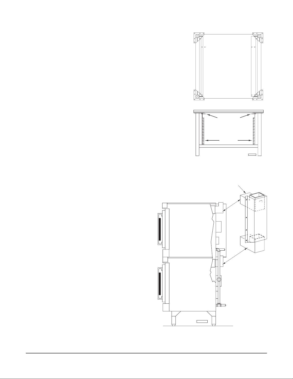
INSTALLING BASIC OVEN
The basic oven must be installed on legs or be mounted on a
modular stand. Installations on concrete bases or other supports
restricting air circulation underneath the oven is not advisable
and may void the warranty.
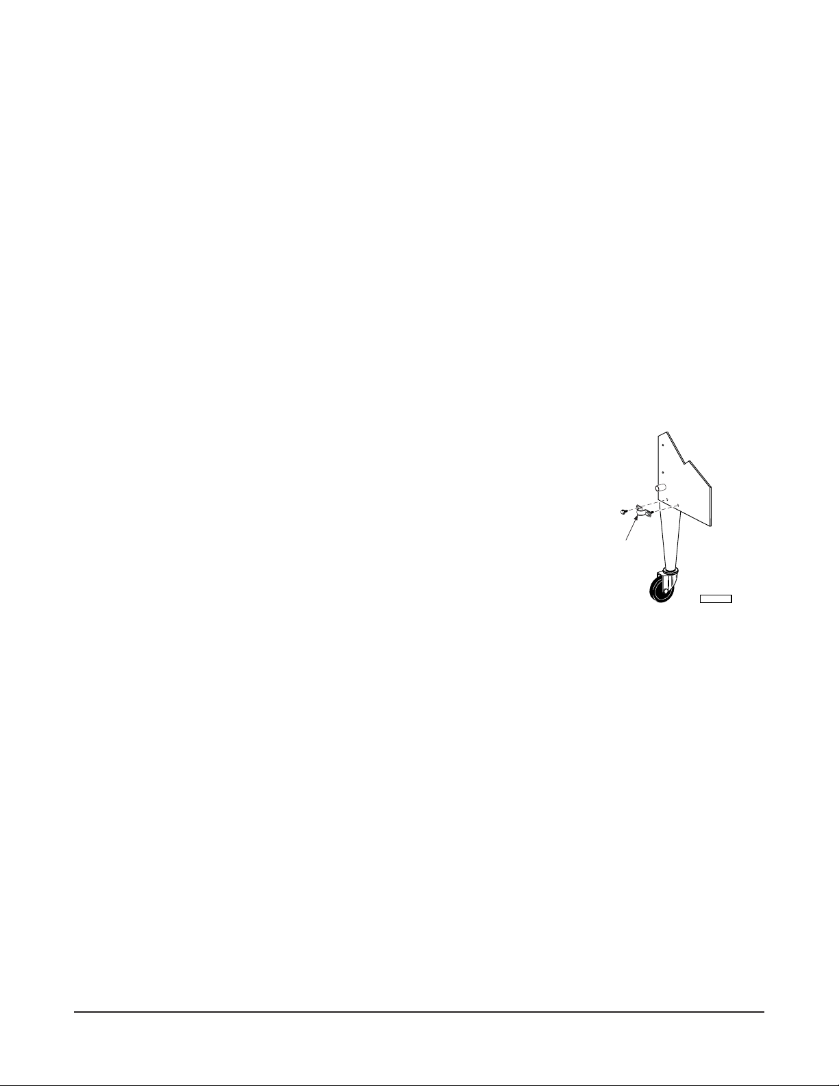
Ovens Mounted on Casters
Ovens mounted on casters must use a flexible connector (not
supplied by Vulcan) that complies with the Standard for
Connectors for Movable Gas Appliances, ANSI Z21.69 • CSA
6.16 and a quick-disconnect device that complies with the
Standard for Quick-Disconnect Devices for Use With Gas
Fuel, ANSI-Z21.41 • CSA 6.9. In addition, adequate means
must be provided to limit movement of the appliance without
depending on the connector and the quick-disconnect device
or its associated piping to limit appliance movement. Attach the
restraining device at the rear of the oven as shown in Fig. 1.
Remove two screws from the rear of the oven and install the tie-down strap shipped with the casters
using these screws (Fig. 1). Attach the gas line strain relief to the tie-down strap at the rear of the oven
(Fig. 1).
If disconnection of the restraint is necessary, turn off the gas supply before disconnection. Reconnect
this restraint prior to turning the gas supply on and returning the oven to its installation position.
Separate instructions for installing casters to the oven are included with the casters.
Note: If the oven is installed on casters and is moved for any reason, it is recommended that the oven
be releveled front to back and side to side.
Fig. 1
CONNECT
GAS LINE
STRAIN RELIEF
HERE
PL-53563
– 6 –
ASSEMBLING STACKED OVENS
Unpack the ovens and stack kit. Position the
oven to be used as the bottom oven on its back
for access to the oven bottom, taking care not to
scratch or damage it. The gas pipe protrudes
beyond the back; provide for this when the oven
is tipped back by resting it on suitable spacers
(2 x 4" [51 x 102 mm], etc.). Attach the four leg
assemblies with the 24 bolts and lockwashers
(six per leg).
Place the lower oven (with legs) on the floor and
remove two
7
/16 inch (11 mm) diameter knockouts
on each side of the top cover. Remove vent
guard and discard it.
Move the oven with legs to the installed position
and place upper oven on top of lower oven using
the locating studs.
Install the stacking flue (Fig. 3) with the four
screws provided.
Connect the piping between the top oven and
bottom oven. For all gas supply connections,
pipe joint compound must be resistant to the
action of propane gases.
Assembling the Legs to the Oven
The legs must be installed on the bottom of the oven. Gently
position the oven on its side, taking care not to scratch or damage
it.
Attach each of the four leg assemblies to the bottom of the oven
with the 24 bolts and lockwashers (six per leg). Carefully raise the
oven to its normal position.
ASSEMBLING THE STAND TO THE OVEN
Attach each of the four leg assemblies to the bottom of the oven
with the 24 bolts and lockwashers (six per leg). Carefully raise the
oven to its normal position.
Attach the undershelf to the legs with eight bolts and lockwashers
(two per leg).
Install the rack guides into the undershelf at desired locations (for
pan or flat rack), then attach the rack supports to the top end of the
rack guides. Attach rack supports to the leg assembly by removing
one middle bolt and reattaching back through the end holes in the
rack support (Fig. 2).
Fig. 2
Fig. 3
STACKING FLUE
PL-53564
BACK
FRONT
RACK SUPPORT
RACK GUIDE
PL-56178
– 7 –
LEVELING
Make sure that the oven racks are level in the final installed position. If the oven is installed on legs,
turn the adjustable feet in or out to level the oven front-to-back and side-to-side. If the oven is installed
on casters, loosen set screws and turn casters in or out to level the oven front-to-back and side-to-side.
Retighten set screws after leveling.
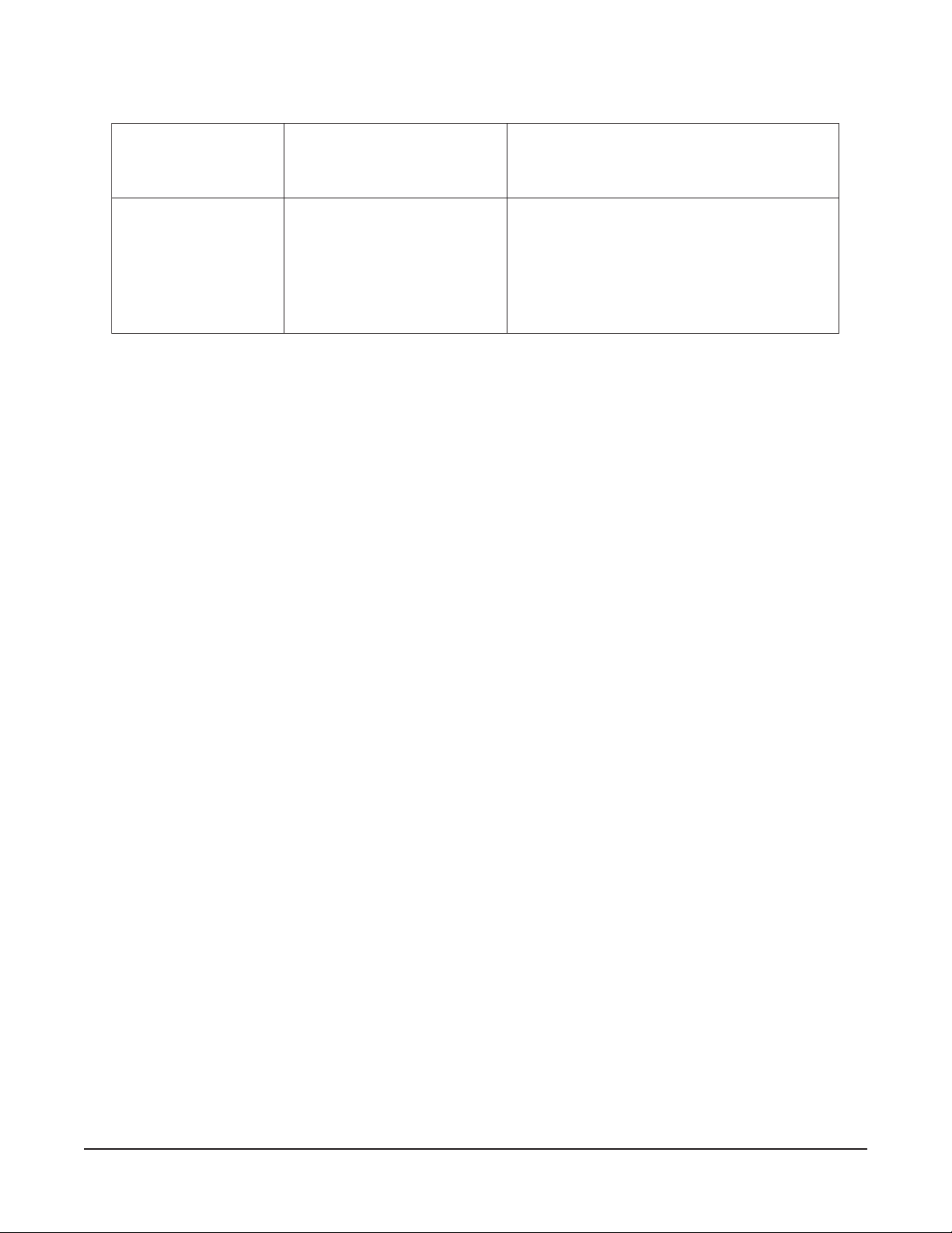
GAS CONNECTION
SAGATAD
LEDOM
GNITARTUPNIERUSSERPDLOFINAM
larutaN
sesaG.P.L
)enaporP(
larutaN
sesaG.P.L
)enaporP(
DG4CV
DG6CV
rh/UTB000,44rh/UTB000,44
.C.W"5.3
)aPk9.0(
.C.W"01
)aPk5.2(
Gas supply connections and any pipe joint compound must be resistant to the action of propane gases.
Location of the gas inlet is at the rear of the oven. Codes require that a gas shutoff valve must be
installed in the gas line ahead of the oven.
Connect gas supply after leveling the oven. The gas supply line must be at least the equivalent of
3
/4 inch (19 mm) iron pipe. Make sure the pipes are clean and free of obstructions, dirt or pipe joint
compound.
The ovens are equipped with fixed burner orifices which coincide with installation elevation.
The oven is provided with a regulator integral to the gas solenoid valve and requires no external
regulator.
CAUTION: The gas pressure regulator provided with this appliance must be used. This regulator is set
for an outlet pressure of 3.5” W.C. (0.9 kPa) natural gas and 10” W.C. (2.5 kPa) propane gas.
WARNING: PRIOR TO LIGHTING, CHECK ALL JOINTS IN THE GAS SUPPLY LINE FOR LEAKS.
USE SOAP AND WATER SOLUTION. DO NOT USE AN OPEN FLAME.
A. CHECK ALL JOINTS PRIOR TO THE GAS VALVE (SOLENOID) BEFORE LIGHTING UNIT.
B. CHECK ALL JOINTS BEYOND GAS VALVE (SOLENOID) AFTER UNIT IS LIT.
After piping has been checked for leaks, all piping receiving gas should be fully purged to remove air.
TESTING THE GAS SUPPLY SYSTEM
When gas supply pressure exceeds
1
/2 psig (3.45 kPa), the oven and its individual shutoff valve must
be disconnected from the gas supply piping system.
When gas supply pressure is
1
/2 psig (3.45 kPa) or less, the oven should be isolated from the gas supply
system by closing its individual manual shutoff valve.
VC4GD
VC6GD
VC4GC
VC6GC

– 8 –
VENT SYSTEM
DO NOT obstruct the flow of flue gases from the flue located on the rear of the oven. It is recommended
that the flue gases be ventilated to the outside of the building through a ventilation system installed by
qualified personnel.
Ovens may use an optional down-draft diverter flue method. This optional down-draft diverter must be
purchased from the oven manufacturer and vented to the outside; otherwise, the installation of any
such device will void all oven certifications and warranties. This oven is suitable for connection to
Type B Gas Vent when used with the draft hood provided.
From the termination of the flue to the filters of the hood venting system, a minimum clearance of
18 inches (457 mm) must be maintained.
Information on the construction and installation of ventilating hoods may be obtained from
Vapor
Removal from Cooking Equipment
, NFPA Standard No. 96 (latest edition), available from the National
Fire Protection Association, Batterymarch Park, Quincy, MA 02269.
ELECTRICAL CONNECTIONS
WARNING: ELECTRICAL AND GROUNDING CONNECTIONS MUST COMPLY WITH THE
APPLICABLE PORTIONS OF THE NATIONAL ELECTRICAL CODE AND/OR OTHER LOCAL
ELECTRICAL CODES.
WARNING: DISCONNECT THE ELECTRICAL POWER TO THE MACHINE AND FOLLOW
LOCKOUT / TAGOUT PROCEDURES.
WARNING: APPLIANCES EQUIPPED WITH A FLEXIBLE ELECTRIC SUPPLY CORD ARE
PROVIDED WITH A THREE-PRONG GROUNDING PLUG. IT IS IMPERATIVE THAT THIS PLUG
BE CONNECTED INTO A PROPERLY GROUNDED THREE-PRONG RECEPTACLE. IF THE
RECEPTACLE IS NOT THE PROPER GROUNDING TYPE, CONTACT AN ELECTRICIAN. DO
NOT REMOVE THE GROUNDING PRONG FROM THIS PLUG.
VC series ovens with 120 V/60 Hz/1 PH electrical specification are equipped with a cord and plug as
standard equipment.
A wiring diagram is located on the inside of the control housing.
BURNER AIR ADJUSTMENT
Although main burner air is adjusted before shipment, it should be checked at the time of installation.
Excessive air will cause flames to lift off a burner when cold or may cause flash-back during normal
cycling of oven, particularly when propane gas is used.
Insufficient air will cause flames to burn with a yellow tip and result in carbon accumulation in the flame
chamber and heat exchanger tubes.
Contact your local Vulcan-Hart servicer if required.
– 9 –
ATADLACIRTCELE
sledoMHP/zH/V
yticapmAtiucriCmuminiM
eciveDevitcetorPmumixaM
SPMA
DG4CV
DG6CV
1/06/021
1/06/802
1/06/042
1/05/042
3/05/)W3(083/022
3/05/)W4(083/022
3/05/)W4(514/042
51
51
51
51
51
51
51
.)noitidetsetal(07-APFN,edoClacirtcelElanoitaNehthtiwecnadroccanidelipmoC
VC4GD
VC6GD
VC4GC
VC6GC
– 10 –
OPERATION
WARNING: THE APPLIANCE AND ITS PARTS ARE HOT. USE CARE WHEN OPERATING,
CLEANING OR PERFORMING ANY MAINTENANCE.
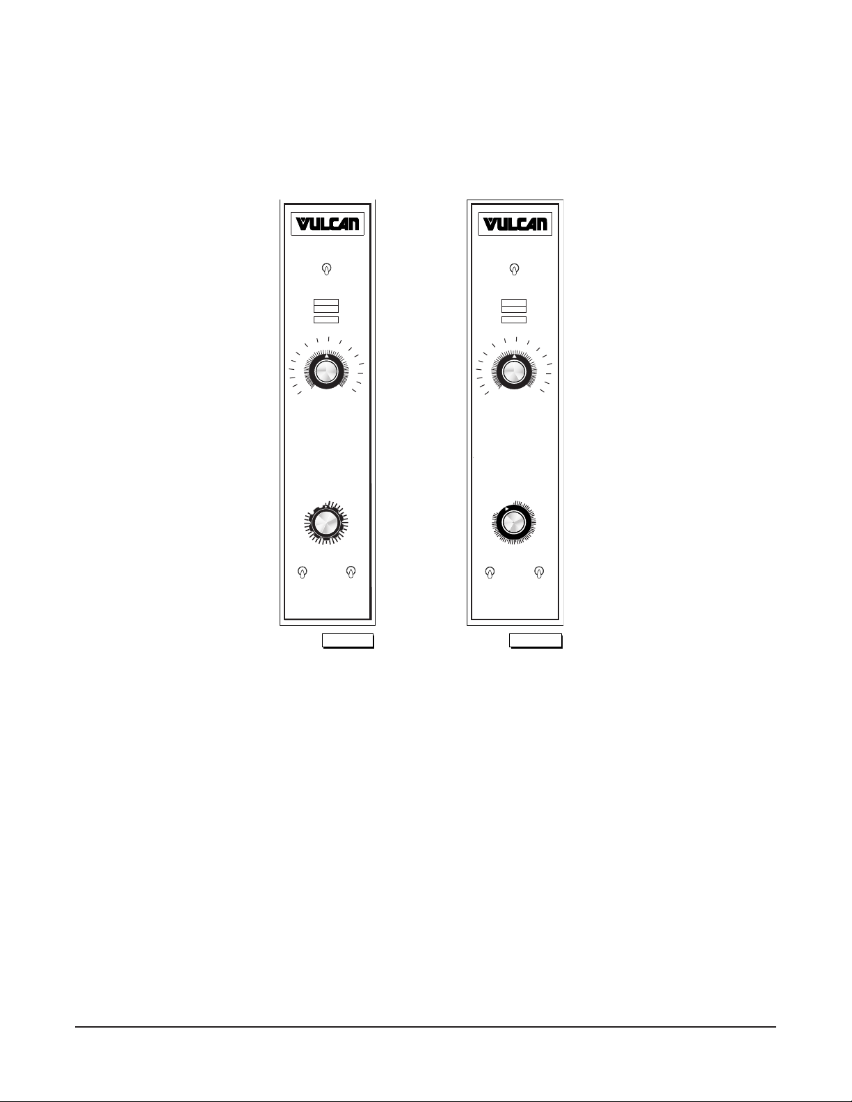
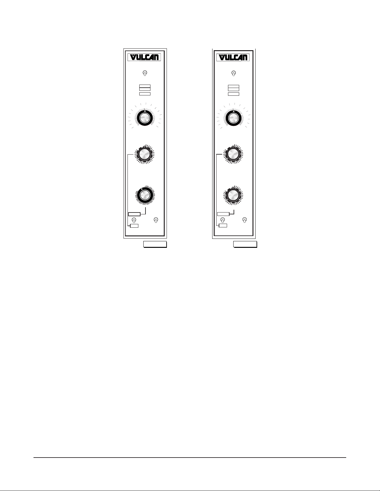
CONTROLS (Models VC4GD and VC6GD Without Roast & Hold)
THERMOSTAT
HI
LO
MASTER SWITCH
OFF
HEAT
ON
IGNITION
OVEN COOL
ON
TIMER
OFF
ON
OFF
LIGHTS
FAN SPEED
LO
150
150
225
250
275
300
325
350
375
200
400
425
450
250
475
500
F
100
C
PL-53547
1
2
3
4
5
0
LIGHTING INSTRUCTIONS
SHUTDOWN INSTRUCTIONS
TURN GAS AND MASTER SWITCH "OFF"
TURN GAS "ON"
PUSH MASTER SWITCH "ON"
IF BURNER FAILS TO LIGHT
TURN GAS "OFF"
WAIT 5 MINUTES FOR RETRIAL
OFF
45
50
55
60
40
35
30
25
20
15
10
5
0
PL-53562
HI
LO
TIMER
ON
OFF
LIGHTS
FAN SPEED
LO
THERMOSTAT
MASTER SWITCH
OFF
HEAT
ON
IGNITION
OVEN COOL
ON
150
150
225
250
275
300
325
350
375
200
400
425
450
250
475
500
F
100
C
LIGHTING INSTRUCTIONS
SHUTDOWN INSTRUCTIONS
TURN GAS AND MASTER SWITCH "OFF"
TURN GAS "ON"
PUSH MASTER SWITCH "ON"
IF BURNER FAILS TO LIGHT
TURN GAS "OFF"
WAIT 5 MINUTES FOR RETRIAL
Master Switch ON — Turns oven control circuits on.
OFF — Turns oven control circuits off.
OVEN COOL — Allows the fan motor to run with the doors ajar to speed ovencooling.
On Light (Amber) — Lit when Master Switch is ON.
Heat Light (White) — Comes on and goes off when the burner cycles on and off.
Ignition Light (Red) — Comes on if burner fails to ignite. When lighting the oven, the IGNITION
light flashes.
Thermostat — Controls oven temperature during cooking operation.
Timer (1 Hr. or 5 Hr.) — Sets the bake time. Buzzer sounds continuously after timer counts down
to 0. Oven does not turn off. Turn Timer to OFF to stop buzzer. When oven
is not in use, keep Timer at OFF position.
Fan Speed Switch — Allows you to select HI or LO Fan Speed.
Lights Switch — Turns the lights in the oven ON or OFF.
– 11 –
CONTROLS (Models VC4GD and VC6GD With Roast & Hold)
OFF
150
150
225
250
275
300
325
350
375
200
400
425
450
250
475
500
F
100
C
THERMOSTAT
1
2
3
4
5
0
PL-53551
ON
OFF
LIGHTS
NORMAL
R & H
FUNCTION
MASTER SWITCH
OFF
HEAT
ON
IGNITION
OVEN COOL
ON
TIMER
OFF
45
50
55
60
40
35
30
25
20
15
10
5
0
R & H TIMER
1
2
3
4
5
OFF
0
PL-53550
ON
OFF
LIGHTS
R & H
FUNCTION
1
2
3
4
5
0
NORMAL
OFF
TIMER
150
150
225
250
275
300
325
350
375
200
400
425
450
250
475
500
F
100
C
THERMOSTAT
MASTER SWITCH
OFF
HEAT
ON
IGNITION
OVEN COOL
ON
R & H TIMER
Master Switch ON — Turns oven control circuits on.
OFF — Turns oven control circuits off.
OVEN COOL — Allows the fan motor to run with the doors ajar to speed ovencooling.
On Light (Amber) — Lit when Master Switch is ON.
Heat Light (White) — Comes on and goes off when the burner cycles on and off.
Ignition Light (Red) — Comes on if burner fails to ignite. When lighting the oven, the IGNITION
light flashes.
Thermostat — Controls oven temperature when Function switch is on NORMAL or during
the first stage of Roast & Hold.
R & H Timer — Sets the first stage cooking time in Roast & Hold.
Timer (1 Hr. or 5 Hr.) — Sets the bake time when Function switch is on NORMAL. Buzzer sounds
continuously after timer counts down to 0. Oven does not turn off at end
of cycle. Turn Timer to OFF to stop buzzer. When oven is not in use, keep
timer at OFF position.
Function Switch — Allows you to select Normal or Roast & Hold (R & H).
Normal: Uses the regular timer and high fan speed.
R & H: Uses the R & H Timer for the first stage of roasting at the
thermostat setting, selects a hold temperature of 160°F (71°C) during
second stage roasting. Uses low fan speed when burners are on.
Lights Switch — Turns the lights in the oven ON or OFF.

– 12 –
BEFORE FIRST USE
Before using the oven for the first time, it must be "burned in" to release any odors that might result from
heating the new surfaces in the chamber.
1. Using a clean, damp cloth, wipe the inside of the oven including the racks.
2. Close the oven doors.
3. Push the Master Switch to ON.
4. Turn the Thermostat to 300°F (149°C) and allow the oven to cycle for 2 hours or until no odor is
detected before pushing the Master Switch to OFF.
LIGHTING MODEL VC4GD AND VC6GD OVENS
1. Turn the main gas supply ON.
2. Push the Master Switch to ON.
3. If the burner fails to light, push Master Switch OFF. Wait 5 minutes for retrial.
If the oven does not light after three trials, turn off the main gas valve and call a qualified servicer.
SHUTDOWN INSTRUCTIONS
1. Turn Master Switch to OFF.
EXTENDED SHUTDOWN
1. Push Power Switch to OFF.
2. Turn gas and electrical power supplies OFF.
USING MODEL VC4GD AND VC6GD OVENS
Preheating
1. Select the proper rack arrangement for the product to be cooked. Refer to RACK ARRANGEMENTS,
page 15.
2. Make sure the doors are closed.
3. Push Master Switch to ON. The amber ON light will come on, indicating that power to the oven
is on.
4. Set the two-speed FAN SWITCH to the desired setting (without Roast & Hold models).
5. Set thermostat as desired. The HEAT light will come on and remain on until the oven reaches set
temperature (approximately 10 to 15 minutes for settings from 300 to 400°F (149 to 204°C)).
Refer to SUGGESTED COOKING GUIDELINES for temperatures and times for various products.
If the burner fails to light, the red IGNITION light will come on and remain on.
6. Prepare product and place in suitable pans. When the white HEAT light goes off, the oven has
reached the desired preheat temperature.

– 13 –
Cooking
1. Open doors and load the product into the oven. Place pans in the center of the racks. Close doors.
2. Set the Timer. After the preset time lapses, turn Timer to OFF position to stop alarm.
3. When product is done, open doors and carefully remove cooked product from the oven. Care
should be taken when wiping up spills, as oven is still hot.
Roast & Hold (When Equipped)
1. Turn the oven ON.
2. Set the Thermostat to the desired setting.
3. Position the Function switch to R & H.
4. Set the R & H TIMER to the desired roasting time.
• The oven will roast the product for the chosen set time and temperature. The oven controller
will automatically switch from the roasting thermostat to the holding thermostat at the end of
the preset roasting time. In holding mode the oven will maintain a temperature of 160°F (71°C)
until the oven is turned off. The blower fan will run while the burner is on and the unit is
operating in R & H.
5. To turn Cook & Hold off, flip the Function switch to the NORMAL position. The oven temperature
will return to the thermostat setting.
End of Day
1. Turn Thermostat to OFF setting.
2. Push Master Switch to OVEN COOL. Leave door ajar while the fan is on to cool the oven.
3. When oven has cooled sufficiently, flip Master Switch to OFF.
4. Turn gas valve to OFF and clean oven.
Extended Shutdown
Repeat Steps 1 through 3 of End of Day. Unplug oven and shut off manual gas valve.
CONSERVING ENERGY— ALL MODELS
• Turn off unused equipment.
• Adjust menu patterns and cooking/baking schedules for optimum equipment use.
• Reduce thermostat settings in slack periods since gas equipment heats up and recovers quickly.
• Preheat only to required cooking temperature for specific food — not higher.
• Do not open the oven door unless absolutely necessary.
• Keep area around the oven door clean and free of food particles.
• Any obstruction that prevents the door from closing completely will adversely affect oven efficiency.
– 14 –
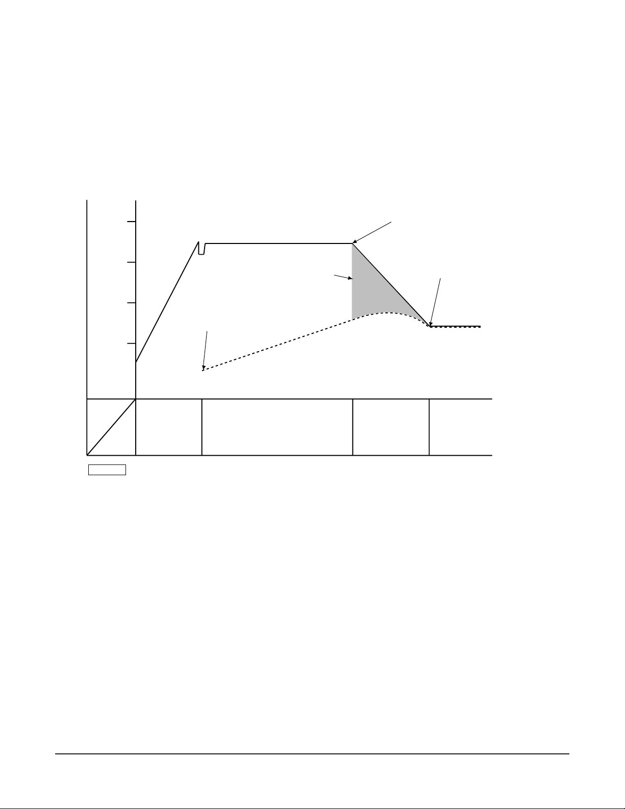
ROAST & HOLD OPERATION — (When Equipped)
Roast & Hold cooks the product in two stages. During first-stage cooking, the oven temperature is
regulated by the temperature setpoint and the R & H Timer setting. After the time counts down to 00:00,
second-stage cooking begins. During second-stage cooking, the heat is off as the temperature in the
oven declines to the hold temperature. The doors should remain closed during second-stage cooking.
When the hold temperature is reached, the oven temperature will be maintained at the hold temperature
until the oven is turned off.
400ºF
300ºF
200ºF
100ºF
ROAST AND HOLD DIAGRAM - Time vs. Temperature
SHORT BEEP.
TIMER DISPLAYS "HOLD."
ROAST THERMOSTAT OFF.
HEATERS OFF UNTIL HOLD
TEMPERATURE IS REACHED.
HEATERS MAINTAIN
HOLD TEMPERATURE.
TIMER DISPLAY FLASHES
"HOLD."
OVEN TEMPERATURE
TIMER DISPLAY COUNTS DOWN.
COOKING FROM
STORED HEAT
LOAD PRODUCT
INTO OVEN
PRODUCT TEMPERATURE
TEMP.
TIME
PREHEAT FIRST-STAGE COOKING SECOND-STAGE
COOKING
(DO NOT OPEN
DOORS)
HOLDING
PL-56291
PROPER UTENSILS
The use of proper utensils can enhance oven operation. Medium and light weight pans allow the
product to warm faster. Roast meats in shallow pans deep enough to hold all juices yet allow free air
circulation.
OPERATING HINTS
When using the convection oven for the first time with a particular food, check the degree of doneness
periodically before the suggested time has elapsed. This will ensure the desired doneness is achieved.
Record your temperature and time settings for various products. The convection oven can provide
consistent and repeatable results.
The convection oven is faster than conventional deck-type ovens; temperature settings are lower and
cook times are shorter. Since recipes and foods are subject to many variations and tastes, the
guidelines regarding times and temperatures in this manual are SUGGESTIONS ONLY. Experiment
with your food products to determine the cooking temperatures and times that give you the best results.
204°C
149°C
93°C
38°C
– 15 –
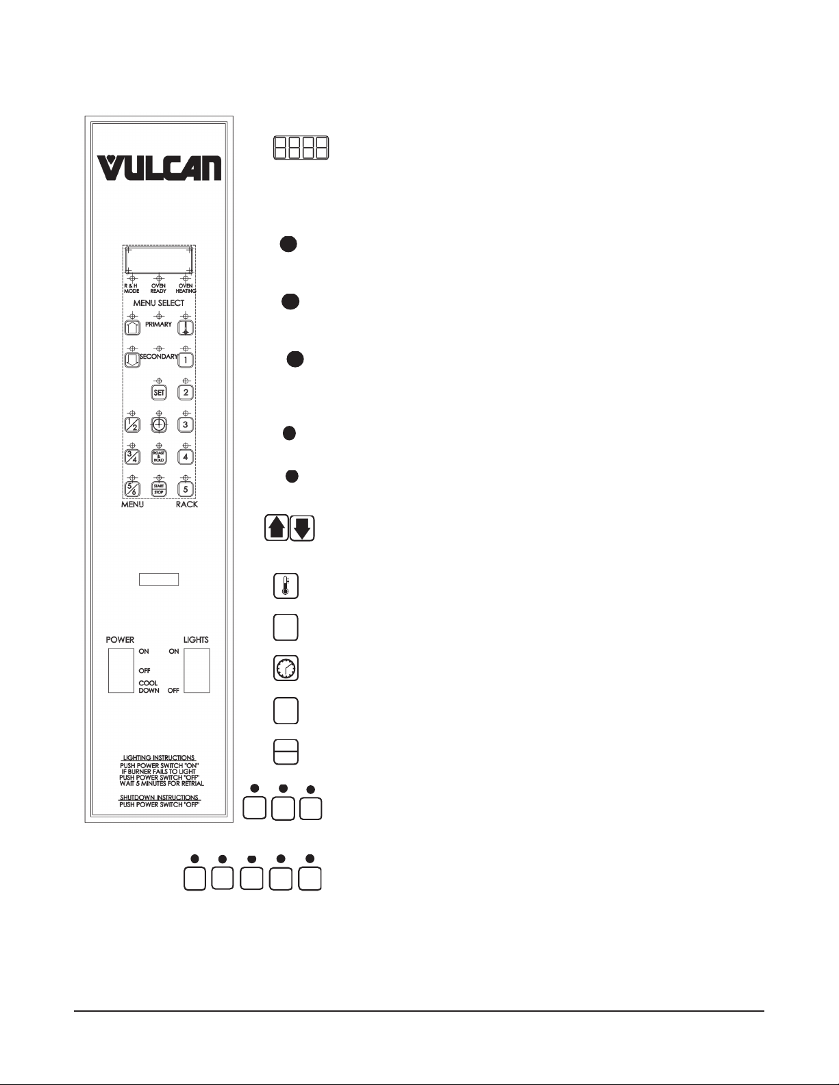
PROGRAMMABLE CONTROLS (Models VC4GC AND VC6GC)
Always displays [HR:Min] when setting the time.
Displays [HR:Min] if the countdown time is more than 1 hour.
Displays [Min:Sec] if the countdown time is less than 1 hour.
Displays temperature in °F.
R & H
MODE
Indicates the oven is in the Roast & Hold Mode.
OVEN
READ
Y
Indicates the oven is preheated and ready for cooking.
OVEN
HEATING
Indicates the oven is preheating or burners have cycled on to
maintain temperature setting.
PRIMARY
Primary indicates menu items 1, 3 or 5.
SECONDAR
Y
Secondary indicates menu items 2, 4 or 6.
Up arrow increases and Down arrow decreases a displayed
time or temperature value (if arrow keys are lit).
TEMPERATURE: Use with SET to set the oven temperature.
SET
SET: Use with time or temperature.
TIME: Use with SET to manually set the cooking time.
ROAST
&
HOLD
Selects Roast & Hold mode; also selects low fan speed.
START
STOP
Press once to start; press a second time to stop.
1/2
3/4
5/6
Select Menu Cook Times. Press once for primary (1, 3 or 5).
Press a second time for secondary (2, 4 or 6). See next page.
1
2
3
4
5
Rack Buttons select individual Menu/Rack Number Cook
Times — once programmed.
 Loading...