


SERVICE MANUAL
GHF SERIES HEAVY DUTY
RANGE MATCHING GAS
FRYERS & FRYMATES
MODELS |
|
GHF91G |
ML-135503 |
GHF90G |
ML-135504 |
- NOTICE -
This manual is prepared for the use of trained Vulcan Service Technicians and should not be used by those not properly qualified. If you have attended a Vulcan Service School for this product, you may be qualified to perform all the procedures described in this manual.
This manual is not intended to be all encompassing. If you have not attended a Vulcan Service School for this product, you should read, in it's entirety, the repair procedure you wish to perform to determine if you have the necessary tools, instruments and skills required to perform the procedure. Procedures for which you do not have the necessary tools, instruments and skills should be performed by a trained Vulcan Service Technician.
Reproduction or other use of this Manual, without the express written consent of Vulcan, is prohibited.
For additional information on Vulcan-Hart or to locate an authorized parts and service provider in your area, visit our website at www.vulcanhart.com
VULCAN-HART |
|
P.O. BOX 696, LOUISVILLE, KY 40201-0696 |
DIVISION OF ITW FOOD EQUIPMENT GROUP, LLC |
|
TEL. (502) 778-2791 |
|
|
|
WWW.VULCANHART.COM |
– 1 – |
FORM 35618 (11-04) |

TABLE OF CONTENTS
GENERAL .............................................................................................................................................................. |
3 |
Introduction ............................................................................................................................................... |
3 |
Installation ................................................................................................................................................ |
3 |
Oil Filtering ................................................................................................................................................ |
3 |
Operation ................................................................................................................................................... |
3 |
Cleaning .................................................................................................................................................... |
3 |
Lighting Pilot ............................................................................................................................................. |
3 |
Specifications ........................................................................................................................................... |
3 |
Gas Data ............................................................................................................................................. |
3 |
Tools ......................................................................................................................................................... |
3 |
Standard ............................................................................................................................................. |
3 |
REMOVAL AND REPLACEMENT OF PARTS ..................................................................................................... |
4 |
Covers and Panels ................................................................................................................................... |
4 |
Door .................................................................................................................................................... |
4 |
Front Panel ......................................................................................................................................... |
4 |
Burners ...................................................................................................................................................... |
4 |
Thermostat ................................................................................................................................................ |
5 |
High Limit .................................................................................................................................................. |
6 |
Thermopile ................................................................................................................................................ |
6 |
Pilot Orifice ............................................................................................................................................... |
7 |
Combination Valve ................................................................................................................................... |
7 |
Fry Tank .................................................................................................................................................... |
8 |
SERVICE PROCEDURES AND ADJUSTMENTS ............................................................................................. |
9 |
Millivolt Controls Test .............................................................................................................................. |
9 |
Thermostat Calibration ............................................................................................................................. |
9 |
Calibration Steps ................................................................................................................................ |
9 |
Pilot Adjustment ...................................................................................................................................... |
10 |
Burners, Nozzles and Orifices ................................................................................................................ |
10 |
Burners .............................................................................................................................................. |
10 |
Nozzles and Orifices ......................................................................................................................... |
10 |
Combination Valve Regulator Adjustment .............................................................................................. |
11 |
ELECTRICAL OPERATION ................................................................................................................................ |
12 |
Control System Description .................................................................................................................... |
12 |
System Condition Quick Check Procedures .......................................................................................... |
12 |
Schematic ................................................................................................................................................ |
13 |
Component Function ............................................................................................................................... |
13 |
TROUBLESHOOTING ......................................................................................................................................... |
14 |
© VULCAN-HART, 2004 |
– 2 – |

GENERAL
INTRODUCTION
Models
This service manual was written for:
GHF91G Gas Fryers and GHF90G Gas Frymates.
INSTALLATION
Generally, installations are made by the dealer or contracted by the dealer or owner. Detailed installation instructions are included in the Installation and Operation Manual, which is sent with each fryer.
OIL FILTERING
Filtering instructions are included in the Installation and Operation Manual.
OPERATION
Detailed operation instructions are included with each fryer in the Installation and Operation Manual.
CLEANING
Detailed cleaning procedures are included in the Installation and Operation Manual.
LIGHTING PILOT
1.Turn thermostat OFF.
2.Push combination valve knob in and turn to OFF.
3.Wait 5 minutes for unburned gas to vent.
4.Push combination valve knob in and turn to PILOT.
5.While holding the combination valve knob in, light the pilot with a lit taper. Hold the combination valve knob in for approximately 30 seconds before releasing.
NOTE: If pilot does not remain lit, repeat steps 2 through 5, but allow a longer period of time before releasing the combination valve knob. Adjust pilot flame, if necessary, as outlined under Pilot Adjustment in Service Procedures and Adjustments.
6. Turn combination valve knob to ON.
SPECIFICATIONS
Gas Data
MODEL |
No. Tubes |
BTU/HR |
GHF91G |
4 |
120,000 |
GHF90G |
0 |
0 |
|
|
|
TOOLS
Standard
•Hand tools (standard set)
•VOM with AC current tester (any quality VOM with a sensitivity of at least 20,000 ohms per volt can be used)
•Gas test kit
•Temperature tester (thermocouple type)
•Manometer
– 3 –
REMOVAL AND REPLACEMENT OF PARTS
COVERS AND PANELS
WARNING: SHUT OFF THE GAS BEFORE SERVICING.
Door
1.Open door and using a 5/16" wrench or ratchet, remove (2) screws securing the top door mounting bracket to the left body side channel.
2.Hold door in one hand and lift the door panel assembly off of the bottom hinge.
3.Reverse this procedure to reinstall the door panel.
Front Panel
1.Using a flat head screwdriver, remove (2) screws holding the front panel in place.
2.Remove the panel from the unit.
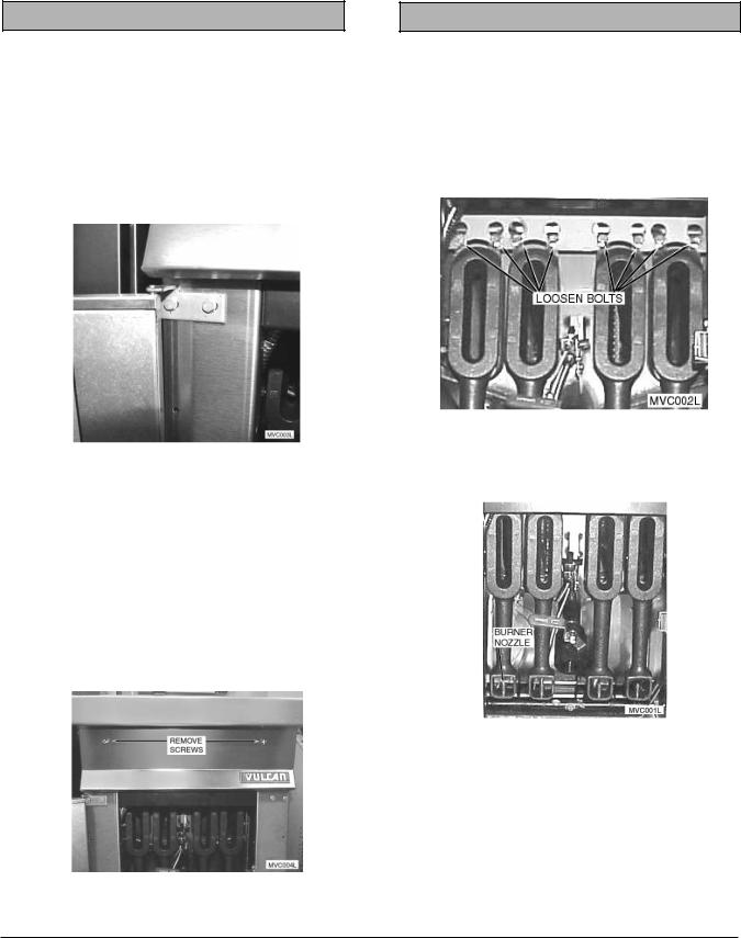
BURNERS
WARNING: SHUT OFF THE GAS BEFORE SERVICING.
1.Open door panel.
2.Loosen (Do not remove) the two mounting bolts at the top of each burner.
3.Push burner up while pulling the bottom of the burner forward to clear the burner nozzle.
4. Reverse the procedure to install.
3. Remove heat shield.
– 4 –

THERMOSTAT
WARNING: SHUT OFF THE GAS BEFORE SERVICING.
1.Drain shortening from fry tank.
2.Remove left burner as outlined under Burners.
3.Remove thermostat knob by pulling knob off thermostat shaft.
4.Remove thermostat mounting screws and remove thermostat from mounting bracket.
5.Remove wire leads from the rear of the thermostat, noting all connections for reassembly.
6. Loosen the packing nut and holding nut.
7. Remove the thermostat bulb from the clamp.
8.Pull the thermostat bulb through the underside of the fry tank and remove the thermostat assembly.
9.Reverse the procedure to install. When installing the new thermostat assembly, do not kink the thermostat capillary. Wrap threads of packing nut with Teflon tape to prevent leakage.
– 5 –
 Loading...