


Service Manual
Trucks
Group 37
Wiring diagram
FH12, FH16 LHD
FH12/FH16: 254453–
TSP23708/1
Foreword
The descriptions and service procedures contained in this manual are based on designs and methods studies carried out up to March 96.
The products are under continuous development. Vehicles and components produced after the above date may therefore have different specifications and repair methods. When this is judged to have a significant bearing on this manual, supplementary service bulletins will be issued to cover the changes.
The new edition of this manual will update the changes.
In service procedures where the title incorporates an operation number, this is a reference to V.S.T. (Volvo Standard Times).
Service procedures which do not include an operation number in the title are for general information and no reference is made to V.S.T.
The following levels of observations, cautions and warnings are used in this Service Documentation:
Note: Indicates a procedure, practice, or condition that must be followed in order to have the vehicle or component function in the manner intended.
Caution: Indicates an unsafe practice where damage to the product could occur.
Warning: Indicates an unsafe practice where personal injury or severe damage to the product could occur.
Danger: Indicates an unsafe practice where serious personal injury or death could occur.
Volvo Truck Corporation
Göteborg, Sweden
Order number: TSP23708/1
© 96 Volvo Truck Corporation, Göteborg, Sweden
All rights reserved. No part of this publication may be reproduced, stored in retrieval system, or transmitted in any forms by any means, electronic, mechanical, photocopying, recording or otherwise, without the prior written permission of Volvo Truck Corporation.
ENG01855
Contents |
|
Component wiring diagram index ........................................................ |
2 |
Component wiring diagrams ................................................................ |
4 |
Illustrations index ................................................................................ |
52 |
Illustrations ........................................................................................... |
53 |
Circuit board (32) electrical centre ................................................... |
108 |
Fuses on circuit board (32) electrical centre ................................... |
110 |
Relays on circuit board (32) electrical centre .................................. |
111 |
Cable harness illustration index ....................................................... |
112 |
List of connectors .............................................................................. |
115 |
List of components ............................................................................ |
121 |
Abbreviations ..................................................................................... |
128 |
Cable colour code .............................................................................. |
129 |
Feedback |
|
1
Group 37 Wiring diagram |
Component wiring diagram index |
|
Component wiring diagram index |
AA |
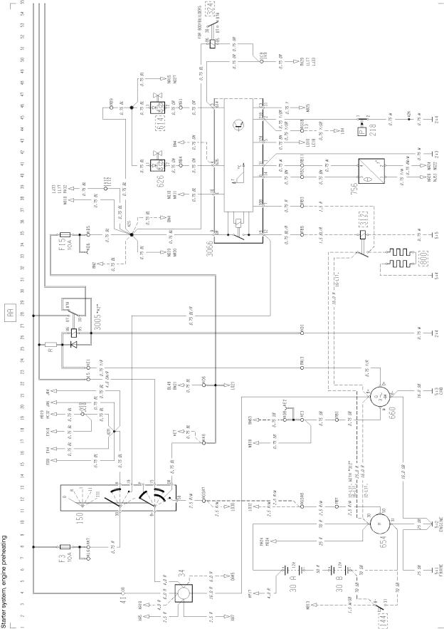
Starter system, engine preheating ................................................................................. |
BL |
Ul, exhaust brake, exhaust pressure governor (FH12) .................................................... |
BN |
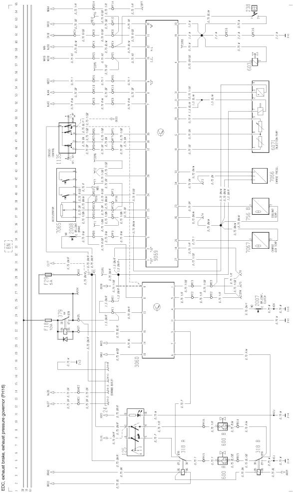
EDC, exhaust brake, exhaust pressure governor (FH16) ................................................ |
CE |
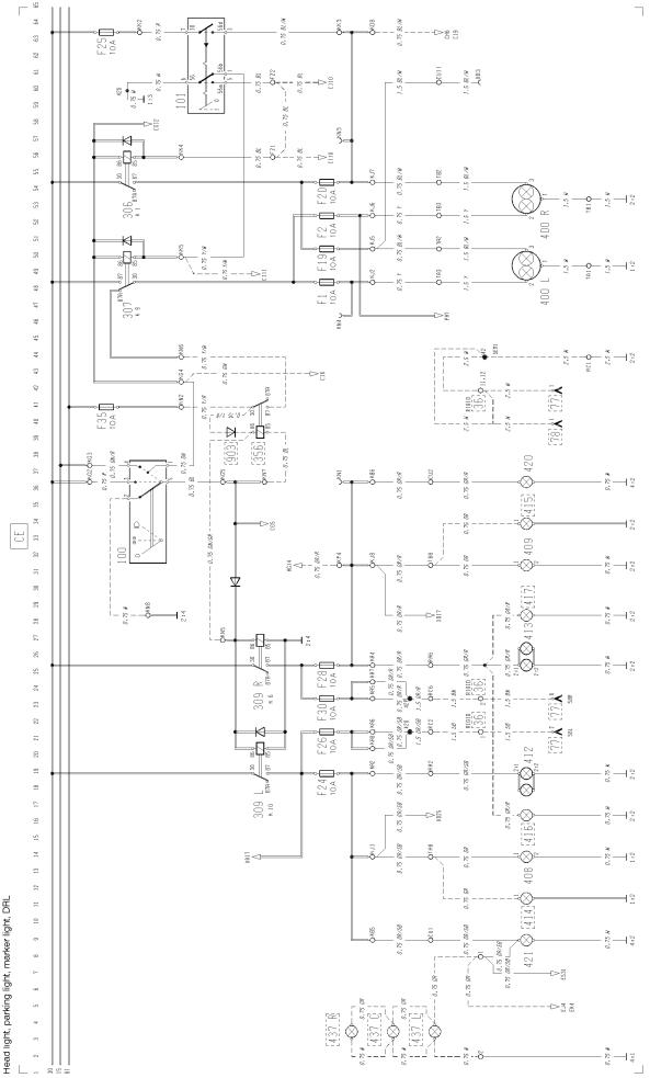
Head light, parking light,marker light, DRL ..................................................................... |
CG |
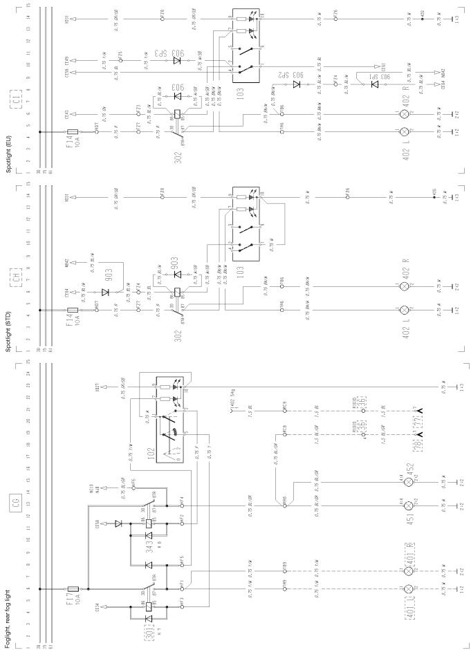
Foglight, rear fog light ...................................................................................................... |
CH |
Spotlight (STD) ................................................................................................................ |
CI |
Spotlight (EU) .................................................................................................................. |
CK |
Brake light ........................................................................................................................ |
CL |
Trailer controlled exhaust brake ....................................................................................... |
CN |
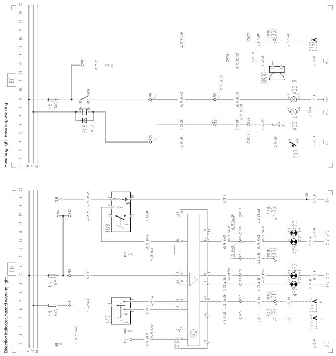
Direction indicator, hazard warning light .......................................................................... |
EA |
Reversing light, reversing warning ................................................................................... |
ED |
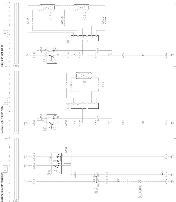
Loading light, fifth wheel light .......................................................................................... |
EJ |
Roof sign light (L1H1/L2H1) ............................................................................................ |
EK |
Roof sign light (L2H2) ...................................................................................................... |
ER |
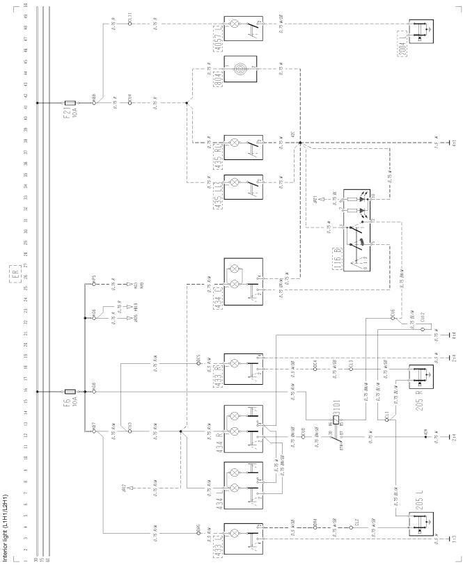
Interior light (L1H1/ L2H1) ............................................................................................... |
ES |
Interior light (L2H2/ L2H3) ............................................................................................... |
EV |
Cigarette lighter ............................................................................................................... |
EX |
12 V outlet in cab ............................................................................................................. |
FA |
Horn ................................................................................................................................. |
GA |
Windscreen wipers and washers, headlamp wipers and washers .................................. |
HA |
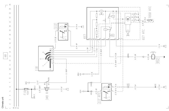
Climate unit ...................................................................................................................... |
HB |
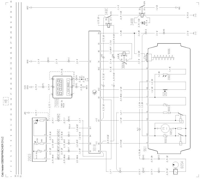
Cab heater EBERSPÄCHER D1LC ................................................................................ |
HC |
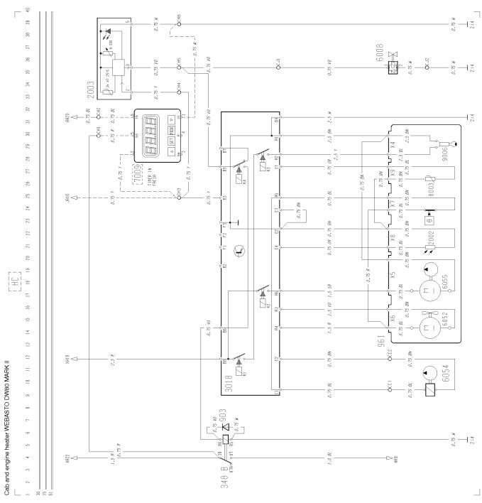
Cab and engine heater WEBASTO DW80 MARK II ........................................................ |
HD |
Electrically heated and adjusted seat .............................................................................. |
HG |
Electrically heated mirror ................................................................................................. |
HH |
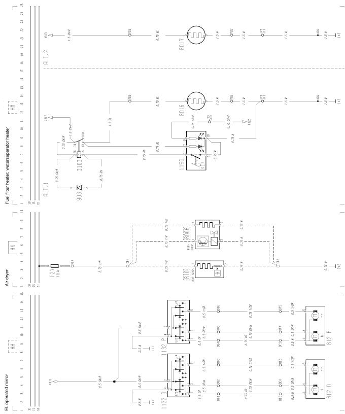
Electrically operated mirror .............................................................................................. |
HK |
Air dryer ........................................................................................................................... |
HM |
Fuel filter heater, waterseperator heater .......................................................................... |
HP |
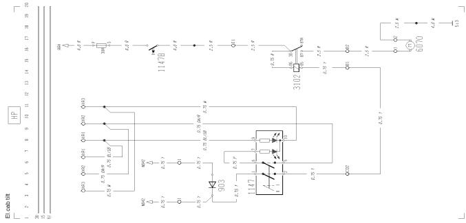
Electrically cab tilt ........................................................................................................... |
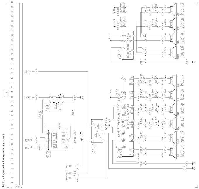
JA |
Radio, voltage divider, loudspeaker, alarm clock ............................................................. |
KA |
Electrically operated window winders .............................................................................. |
KB |
Electrically operated sunroof ........................................................................................... |
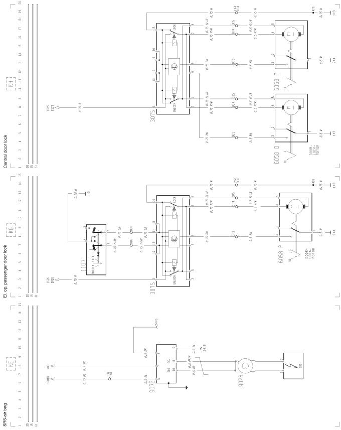
KE |
SRS-air bag ..................................................................................................................... |
KG |
Electrically operated passenger door lock ....................................................................... |
KH |
Central door lock .............................................................................................................. |
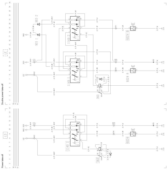
LD |
Power take-off .................................................................................................................. |
page 4 page 5 page 6 page 7 page 8 page 8 page 8 page 9 page 9 page 10 page 10 page 11 page 11 page 11 page 12 page 13 page 14 page 14 page 15 page 15 page 16 page 17 page 18 page 19 page 19 page 20 page 20 page 20 page 21 page 22 page 23 page 23 page 24 page 24 page 24 page 25
2
Group 37 Wiring diagram |
Component wiring diagram index |
LE
LG
LJ
LL
LO MA MD MN MP MQ MR MS MV MW MX MY NA NB NC NG NJ NO OA OG PA XA XD ZA ZD ZE
Double power take-off ......................................................................................................
Differential lock ................................................................................................................
Bogie lift, 3rd axle lock (RADT-LA) ..................................................................................
3rd axle lock (RADT-A6S) ...............................................................................................
GEARTRONICautomatic gear shift ...............................................................................
Bogie lift hydraulic ............................................................................................................
Bogie lift hydraulic, with axle load limiter .........................................................................
Air suspension 4x2 ..........................................................................................................
Air suspension 6x2, bogie lift, < 15 tonnes ......................................................................
Air suspension 6x2, bogie lift, < 15 tonnes with time limitation ........................................
Air suspension 6x2, bogie lift, pusher ..............................................................................
Air suspension 6x2, bogie lift, 15 tonnes .........................................................................
AIR-DUMP-drive axle load increase (RADT-A8) .............................................................
AIR-DUMP-drive axle load increase with time limitation (RADT-A8) ...............................
Air suspension 6x4 ..........................................................................................................
Air suspension 6x4, <15 tonnes with time limitation ........................................................
Instrument LHS unit (standard design) ............................................................................
Instrument central unit ....................................................................................................
Instrument RHS unit (standard design) ...........................................................................
Instrument LHS unit (DIS) ...............................................................................................
Instrument RHS unit (DIS) ...............................................................................................
Instrument control lamps module ....................................................................................
ABS, anti-lock brakes .....................................................................................................
Retarder ...........................................................................................................................
Headlight level control .....................................................................................................
Extra fuses .......................................................................................................................
Key switch relay, rheostat ................................................................................................
Earth connections ............................................................................................................
ADR battery main switch, current limiter ........................................................................
Air heater EBERSPÄCHER TMD (only french market) ...................................................
page 25 page 26 page 27 page 27 page 28 page 29 page 30 page 31 page 32 page 33 page 34 page 35 page 36 page 36 page 37 page 38 page 39 page 40 page 41 page 42 page 43 page 44 page 45 page 46 page 47 page 47 page 48 page 49 page 50 page 51
3
Group 37 Wiring diagram |
Component wiring diagrams |
Component wiring diagrams
T3007945
4

Group 37 Wiring diagram |
Component wiring diagrams |
T3007944 |
5 |
|
Group 37 Wiring diagram |
Component wiring diagrams |
6 |
T3008017 |
Group 37 Wiring diagram |
Component wiring diagrams |
T3008018 |
7 |
|
Group 37 Wiring diagram |
Component wiring diagrams |
T3008019
8
Group 37 Wiring diagram |
Component wiring diagrams |
T3008020
9
Group 37 Wiring diagram |
Component wiring diagrams |
T3008021
10
Group 37 Wiring diagram |
Component wiring diagrams |
T3008022
11
Group 37 Wiring diagram |
Component wiring diagrams |
T3008023
12

Group 37 Wiring diagram |
Component wiring diagrams |
T3008024
13

Group 37 Wiring diagram |
Component wiring diagrams |
T3008025
14

Group 37 Wiring diagram |
Component wiring diagrams |
T3008026
15
Group 37 Wiring diagram |
Component wiring diagrams |
T3008027
16
Group 37 Wiring diagram |
Component wiring diagrams |
T3008028
17
Group 37 Wiring diagram |
Component wiring diagrams |
T3008029
18
Group 37 Wiring diagram |
Component wiring diagrams |
T3008030
19
Group 37 Wiring diagram |
Component wiring diagrams |
T3008031
20
Group 37 Wiring diagram |
Component wiring diagrams |
T3008032
21
Group 37 Wiring diagram |
Component wiring diagrams |
T3008033
22

Group 37 Wiring diagram |
Component wiring diagrams |
T3008034
23
Group 37 Wiring diagram |
Component wiring diagrams |
T3008035
24
Group 37 Wiring diagram |
Component wiring diagrams |
T3008036
25

Group 37 Wiring diagram |
Component wiring diagrams |
T3008037
26

Group 37 Wiring diagram |
Component wiring diagrams |
T3008038
27

Group 37 Wiring diagram |
Component wiring diagrams |
28 |
T3008039 |
|
 Loading...