


TWOAND FOUR-DOOR
CARS
( 121/122 S M)
DESCRIPTIONDRIVING
SERVICING
BEFORE YOU START DRIVING YOUR NEW VOLVO
PLEASE READ THROUGH THIS
INSTRUCTION BOOK CAREFULLY. IT CONTAINS ALL THE INFORMATION YOU NEED TO BE ABLE TO DRIVE AND SERVICE YOUR VEHICLE IN THE BEST POSSIBLE WAY. BY FOLLOWING THE INSTRUCTIONS GIVEN IN THIS BOOK, YOU WILL FIND THAT
YOUR VOLVO WILL COME UP TO ALL THE EXPECTATIONS CONCERNING ECONOMICAL OPERATION AND EXCELLENT PERFORMANCE THAT YOU HAVE EVERY RIGHT TO EXPECT OF
A TOP-QUALITY VEHICLE.
THIS INSTRUCTION BOOK IS NOT INTENDED TO
BE A COMPREHENSIVE TECHNICAL MANUAL AND
DOES NOT CLAIM TO MAKE THE
READER INTO A PERFECT CAR MECHANIC. IT WILL, HOWEVER, SHOW YOU HOW TO LOOK AFTER YOUR VEHICLE SO THAT TROUBLE IN THE FUTURE
CAN BE AVOIDED
AB VOLVO
DO NOT WAIT UNTIL SOMETHING GOES WRONG BEFORE YOU START READING THIS BOOK. READ IT NOW.
THE SHORT TIME THIS TAKES WILL MORE THAN REPAY YOU IN THE LONG RUN.
THE BETTER YOU KNOW YOUR VOLVO, THE BETTER SERVICE IT CAN GIVE YOU.
THIS BOOK CAN CONTAIN SOME VALUABLE INFORMATION EVEN FOR AN EXPERIENCED MOTORIST FINALLY, WE WOULD LIKE TO EXPRESS OUR
APPRECIATION FOR THE CONFIDENCE YOU HAVE SHOWN IN THE NAME OF VOLVO BY CHOOSING A VOLVO VEHICLE.
WE ARE SURE THAT THE DEMANDS YOU MAKE ON YOUR VOLVO WILL BE MORE THAN SATISFIED, APART FROM THE FACT THAT YOU WILL ENJOY DRIVING IT, AND THAT IT WILL GIVE YOU FAITHFUL SERVICE FOR MANY, MANY MILES.
3
CONTENTS
4
CONTENTS
VOLVO SERVICE
Volvo Service Organization
In order to get the most out of the invested capital represented by a car, it must be looked after and serviced rationally. Volvo has gone to a great amount of trouble in the design and selection of material to ensure that the car in question only requires a minimum of servicing. All this work will be in vain unless we can count on your co-operation - that is to say, that you make sure that your vehicle gets the regular 'servicing it needs. In order to help you, Volvo has built up a world-wide service organization. All Volvo dealers have specially trained personnel and receive a continuous supply of technical information from the Volvo Service Organization concerning repair and adjustment work. They have also special tools, designed at the Volvo factory.
All Volvo dealers have a comprehensive stock of spare parts which is your guarantee for genuine Volvo spares. This is why our dealers are in the very best position to give your vehicle first-class service concerning both maintenance operations and repairs. You should also refer to your dealer if you need information about your Volvo that is not included in this instruction book.
It is not only in your own country that there is a Volvo workshop within easy reach but Volvo also has a widely distributed service network in other countries too.
6
VOLVO SERVICE
Warranty and Service Booklet
A warranty and service booklet accompanies each vehicle when it is delivered. This book contains a coupon entitling you to a cost-free service inspection after 2 500 km (1 500 miles) running. If possible, let the dealer who supplied the vehicle carry out this service inspection. If necessary, however, any of our dealers can do this.
I f our six-month guarantee is to apply, we make one absolute condition and that is that the above-mentioned cost-free inspection is carried out at roughly the mileage shown and that the vehicle has been looked after in accordance with the instructions in this book.
Service Inspections
After the cost-free service inspection has been carried out, you should make an agreement with your dealer concerning continued, regular ser- vice inspections in accordance with the suggestions made in our Service Book. Thorough and regular servicing is o f vital importance for the performance and length o f life o f the vehicle.
Always use genuine Volvo spares.
7
DESCRIPTION
General
The Volvo 121/122 S is a twoor four-door, five-seater car. Many colours are available and in each particular case the colour of the internal fittings and upholstery harmonizes with the external finish of the car. In addition to a spacious luggage compartment, where the spare wheel and tool kit are stowed, there is also plenty of storage space inside the car itself, such as a shelf with its own lighting under the dashboard, a recessed hat shelf below the rear window and roomy pockets on the inside of the front doors. Standard equipment on the car includes a trip meter in the speedometer, a windscreen washer and a back-up light which goes on automatically when the reverse gear is engaged. Both front seats are fitted with safety belts. The car is of the integral construction type so that there is no separate frame. The front and rear suspensions as well as the engine and transmission are attached directly to the body. The surface finish of the body is synthetic and the primer used rustproofs the body. The car is also thief-proof since the connection between the ignition switch and the ignition coil is in the form of an armoured cable.
8
Type designations
This instruction book deals with vehicles having the following type designations:
Type designation |
M |
Engine |
Gearbox |
|||
121341 |
M or |
121342 |
B 18 A |
M 40 |
||
121361 |
M or |
121362 |
M |
B 18 A |
BW 35* |
|
122341 |
M or |
122342 |
M |
B 18 D |
M 40 |
|
122351 |
M or |
122352 |
M |
B 18 D |
M 41 |
|
122461 |
M or |
122462 |
M |
B 18 D |
BW 35* |
|
131211 |
M or |
131212 |
M |
B 18 A |
M 30 |
|
131341 |
M or 131342 |
M |
B 18 |
A |
M 40 |
|
131361 |
M or 131362 |
M |
B 18 |
A |
BW 35* |
|
132341 |
M or 132342 M |
B 18 |
D |
M 40 |
||
132461 |
M or 132462 M |
B 18 |
D |
BW 35* |
||
On the USA market, 12234 and 13234 have designations 12244 and 13244 respectively.
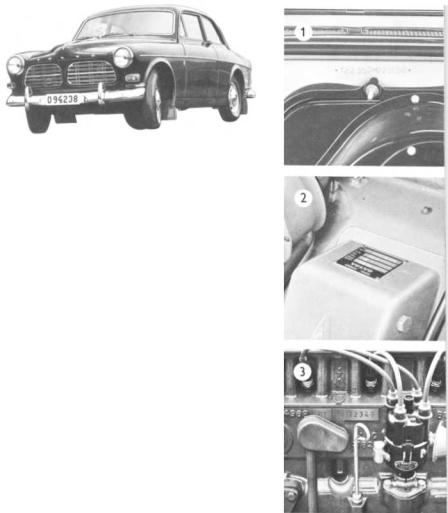
Moreover, the letter M is not included in the type designation for the models on the USA market. 1. The type designation and chassis number are stamped on the cowl under the bonnet.
2. Stamped on a plate to the left under the bonnet is the type designation together with the code numbers for colour and upholstery.
3. The engine type designation, part number and |
|
serial |
number are given on the left-hand side of |
the cylinder block. The last figures of the part |
|
number are stamped on a tab. The serial number |
|
follows this with all the figures stamped on. For |
|
i dentifying the engine, both the part number and |
|
serial |
number should be quoted, for example |
496801-12345.
:j.) See separate supplement.
In all correspondence concerning your vehicle with the dealer and when order- i ng spare parts, the type designation, chassis and engine number should always be quoted.
DESCRIPTION
The engine is a four-cylinder carburettor unit with overhead valves. The pistons are made of light-alloy and the upper compression ring on each piston is chromed. The main bearings and connecting rod bearings are replaceable. The crankshaft is statically and dynamically balanced.
Engine type B 18 A has an output of 85 h.p. (SAE) and is equipped with Zenith-Stromberg horizontal carburettor. and is equipped Engine type B 18 D has an output of 100 h.p. ( SAE )
with twin SU horizontal carburettors.
Fuel system
The fuel system is fed from the tank to the carburettor by a fuel pump which is driven by a cam on the engine camshaft. There is a filter in the fuel pump which traps water and other impurities in the fuel.
Lubricating system
The engine lubrication is taken care of by a gear pump which sucks up oil from the sump on the bottom of the engine and forces it through the oil filter out to the lubricating points in the engine. A relief valve is built into the oil filter which prevents the oil pressure from reaching excessively high values.
Cooling system
The engine is water-cooled and the cooling system is of the pressure type. Water is circulated by means of a pump fitted on the fan shaft. A thermostat with an opening temperature of about 76 ° C (169 ° F) prevents the cooling water from passing through the radiator before the engine has reached its normal working temperature.
1 0
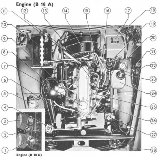
1. |
Carburettor (B 18 D) |
12. |
Oil dipstick |
2. |
Float chamber (B 18 D) |
13. |
Distributor |
3. |
Air cleaner (B 18 D) |
14. |
Heater |
4. |
Expansion tank with |
15. |
Starter motor |
|
filler cap for coolant |
6 |
Ignition coil |
5. |
Charging control |
17. Plate with type desig- |
|
6 |
Dynamo |
|
nation and code for |
7. |
Oil filler cap |
|
colour and upholstery |
8. |
Air cleaner (B 18 A) |
8 |
Fusebox |
9. |
C rburettor (B 18 A) |
19. |
Brake fluid container |
10. |
Battery |
20. |
Clutch fluid container |
11. |
Hoses for heater system |
|
|
21.Relay for back-up light
22.Relay for headlight
23.flasher
Motor for windscreen washers
24.Fluid container for windscreen washers
25.Oil trap
26.Fuel pump
27.Steering box
28.Horn
1 1
DESCRIPTION
Electrical system |
|
|
The electrical system is of the 12-volt type and is fitted with a volt- |
|
age control dynamo. The starter motor is controlled from the instrument |
|
panel by means of the ignition key. This key also forms the main switch |
|
for the rest of the electrical system. The cables to the headlights, parking |
|
lights and internal lighting, however, are not taken over the ignition |
|
switch but can be switched on and off without the ignition key being in |
|
position. |
Lighting |
|
|
The lighting on the vehicle consists of two headlights (full and dipped) |
|
together with two combined flasher and parking lights. At the rear the |
|
lighting consists of two tail lights including flashers, combined lamps for |
|
the tail lights and brake warning lights, and the back-up light. Internal |
|
lighting consists of a roof light above the rear view mirror and a light |
|
for the parcel shelf. |
Fuses |
See pages 42-44 concerning replacement of bulbs. |
The electrical system is protected by means of fuses fitted in a fusebox to |
|
|
the left on the bulkhead under the bonnet. When replacing a fuse, be sure |
|
that you use a one of the right rating. If one of the fuses should blow |
|
repeatedly, do not fit a more powerful fuse. Instead, take the vehicle to |
|
a workshop for a check of the electrical system. |
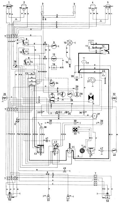
1. |
Flasher and parking |
22. Battery |
|
screen wiper and |
||
2. |
light, left |
23. Fusebox |
|
washer |
|
|
Headlight, left |
24. Brake contact |
43. Lighting switch |
||||
3. |
Horn |
25. |
Door contact, left |
44. Ignition switch |
||
4. |
Headlight, right |
26. Light signal device |
45. |
Cigarette lighter |
||
5. |
Flasher and parking |
27. |
Relay for horn |
46. |
Control for |
|
6. |
light, right |
28. |
Overdrive switch') |
47. |
ventilation fan |
|
Connector |
29. |
Roof light |
Glove compartment |
|||
7. |
Junction block |
30. Switch for roof |
|
lighting |
|
|
8. |
Relay for headlight |
|
light |
48. Switch for glove |
||
|
signal |
31. Flasher unit, direc- |
|
compartment |
||
9. |
Reversing light |
32. |
tion indicators |
|
lighting |
|
contact |
Door contact, right |
49. Fuel gauge |
||||
10. |
Distributor |
33. |
Control lamp for |
50. |
impulse unit |
|
11. |
Dynamo |
34. |
charging |
Rear lamp, left, with |
||
12. |
Charging control |
Control lamp for |
|
rear light, stop light, |
||
13. |
Relay for reversing |
35. |
fullbeam headlights |
|
flasher and back-up |
|
14. |
light |
Control lamp for |
51. |
light |
|
|
Relay for over- |
36. |
direction indicators |
Number plate |
|||
15. |
drive') |
Control lamp for |
52. |
lighting |
|
|
Overdrive contact') |
|
oil pressure |
Rear lamp, right, |
|||
16. Ignition coil |
37. Fuel gauge |
|
with rear light, |
|||
17. |
Oil pressure |
38. |
Windscreen wiper |
|
stop light, flasher |
|
18. |
warning indicator |
39. Instrument lighting |
|
and back-up light |
||
Foot dipper switch |
40. |
Ventilation fan |
A = White E = Grey |
|||
19. Solenoid for |
41. |
Control lamp for |
B=Black |
F =Yellow |
||
|
overdrive') |
42. |
overdrive |
C= Blue |
G=Brown |
|
20. Starter motor |
Control for wind- |
D = Green H =Red |
||||
21. |
Windscreen washer |
|
|
I = Spare lead |
||
12 |
1) Applies only to cars equipped with overdrive |
|
DESCRIPTION
Power transmission
Clutch The function of the clutch is to transmit the power from the engine to the gearbox. The clutch is of the single dry plate type with diaphragm spring. The diaphragm spring 'functions partly as a lever when declutching and partly as a pressure spring when engaging.
Gearbox
The gearbox is used to regulate the speed ratio between the engine and the rear axle so that the engine always operates in its most favourable speed range. The gearbox is synchronised on all the forward gears; this means that gear-changing can be carried out without double declutching. Since the gearbox is fitted with helical gears and the gear lever is rubber insulated, excellent sound insulation is obtained. See page 57 for data.
Propeller shaft
The propeller shaft, which is the connecting link between the gearbox and the rear axle, is divided into two sections. The forward section is journalled at its rear end in a bearing housing suspended in a rubberized ring.
Rear axle
The driving power of the engine is transmitted from the propeller shaft to the rear wheels through the rear axle. The rear axle is of the hypoid type, i.e. drive pinion is below the centre line of the drive shafts. See page 57 for data.
Brakes
The vehicle is equipped with disc brakes at the front and drum brakes at the rear as standard. The brake system is also provided with a reducer valve, which prevents involuntary locking of the rear wheels.
The footbrake system is hydraulic and influences all four wheels. The hydraulic system consists of a 'fluid-filled master cylinder which, when the brake pedal is depressed, transmits the brake pressure through the brake fluid in the lines to the wheel unit cylinders. The plungers in these are then pressed outwards and apply the brake shoes or brake pads respectivly.
Vehicles fitted with the B 18 D engine are also provided with vacuum type servo brake cylinders.
The handbrake system operates mechanically on the rear wheels.
Wheels and tyres
14
The vehicle has pressed steel wheels with lugs for the attachment of the hub caps. All wheels are carefully balanced and the tyres are of the tubeless type.
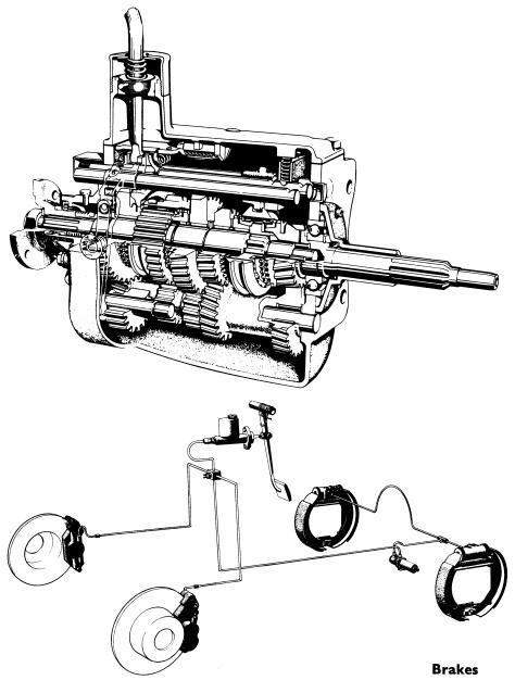
Gearbox
1 5
DESCRIPTION
Body
Bonnet
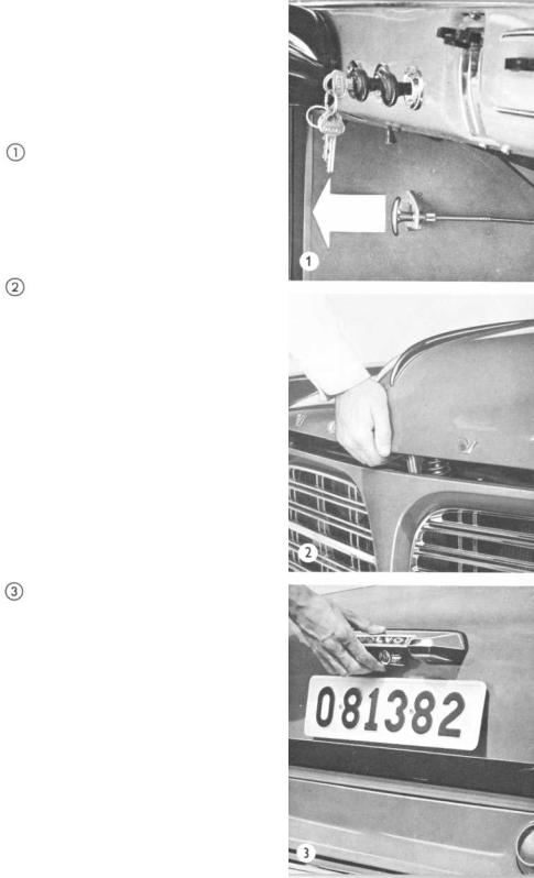
The bonnet is fitted with a catch which is operated from the driving seat through a handle located to the left under the instrument panel. The bonnet catch is released by pulling the handle out.
When the bonnet catch handle has been released inside the car, the bonnet is still retained by a safety catch. After this is pressed in as shown, the bonnet can be lifted up. When the bonnet is closed the bonnet catch is automatically locked and cannot be lifted until the handle inside the car has been pulled again. Check to make sure that the bonnet is properly secured when it is closed.
Luggage compartment
The door key is used to lock the luggage compartment, which is opened by pressing the handle upwards as shown. The luggage compartment lid is balanced and does not need to be held up. To the left in the compartment there is room for the spare wheel and tool kit. Always make sure that the spare wheel is fastened securely and that the tool kit is firmly stowed, otherwise irritating rattles can occur.
16
Doors and locks
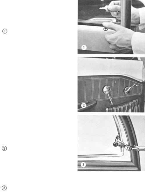
There is a lock with a keyhole on each of the front doors. All the doors can be locked from inside the car by pressing down the lock buttons on the window ledge. On the rear doors, this button must first be pulled up before the doors can be opened from the inside. This is an important safety factor if children are alone in the back. All the doors can be locked by pressing down the internal lock button and then closing the doors. Do not leave the keys in the car, otherwise you can easily lock yourself out.
Many people make it a habit of pressing down all the lock buttons. In itself this is not an extra safety precaution. On the other hand, however, the passengers are locked in and this might be dangerous should an accident occur, especially involving fire. For this reason you should always leave at least one door (for example, one or both front doors) "unlocked" when driving.
The doors are opened from the inside by turning the handle to the rear. The ventilation windows for the doors are opened by unscrewing the lock stud, after which it can be pressed in and the handle turned upwards. With the stud in the screwedin position, the handle is locked.
The rear side windows of two-door cars can be partly opened by setting the handle at the rear edge in different positions (does not apply to 13121).
In order to prevent freezing-up of the locks, a suitable anti-freeze agent should be used in cold weather. If the locks are already frozen, do not exert undue force on the key otherwise you might break it. Instead, heat it with a match or similar and place it quickly into the keyhole.
 Loading...