


T1 other 1968 1979
Owners Workshop Manual
Downloaded from www.Manualslib.com manuals search engine

VW Transporter
1600
Owners
Workshop
Manual
by J H Haynes
Member of the.Guild of Motoring Writers
and DH Stead
Models covered:
All Volkswagen Transporter 1600 models with 1584 cc
(96.7 cu in) engine
Does not cover the alternative bodies and conversions produced by specialist
manufacturers
ISBN 0 85696 660 6
© Haynes Publishing Group 1990
All rights reserved. No part of this book may be reproduced or transmitted in
any form or by any means, electronic or mechanical, including photocopying,
recording or by any information storage or retrieval system, without permission
in writing from the copyright holder.
ABCDE
FGHU
KLM
Printed in the USA
(082
- 2S6)
MEMBER
Haynes Publishing Group
Sparkford Nr Yeovil
Somerset BA22 7JJ England
Haynes Publications, Inc
861 Lawrence Drive
Newbury Park
California 91320 USA
Downloaded from www.Manualslib.com manuals search engine

Acknowledgements
Thanks are due to the VW organisation for the supply of
technical information and certain illustrations. Castrol Limited
provided lubrication details and the Champion Sparking Plug
Company supplied the illustrations showing the various spark
About this manual
plug conditions.
, Lastly, thanks are due to all those people at Sparkford who
helped in the production of this manual.
Its aim
The aim of this manual is to help you get the best value from
your vehicle. It can do so in several ways. It can help you decide
what work must be done (even should you choose to get it
done by a garage), provide information on routine maintenance
and servicing, and give a logical course of action and diagnosis
when random faults occur. However, it is hoped that you will
use the manual by tackling the work yourself. On simpler jobs it
may even be quicker than booking the car into a garage and
going there twice, to leave and collect it. Perhaps most
important, a lot of money can be saved by avoiding the costs a
garage must charge to cover its labour and overheads.
The manual has drawings and descriptions to show the
function of the various components so that their layout can be
understood. Then the tasks are described and photographed in a
step-by-step sequence so that even a novice can do the work.
Its arrangement
The manual is divided into twelve Chapters, each covering a
logical sub-division of the vehicle. The Chapters are each
divided into Sections, numbered with single figures, eg 5; and
the Sections into paragraphs (or sub-sections), with decimal
numbers following on from the Section they are in, eg 5.1, 5.2,
5.3 etc.
It is freely illustrated, especially in those parts where there is
a detailed sequence of operations to be carried out. There are
two forms of illustration: figures and photographs. The figures
are numbered in sequence with decimal numbers, according to
their position in the Chapter - eg Fig. 6.4 is the fourth
drawing/illustration in Chapter 6. Photographs carry the same
number (either individually or in related groups) as the Section
or sub-section to which they relate.
There is an alphabetical index at the back of the manual as
well as a contents list at the front. Each Chapter is also preceded
by its own individual contents list.
References to the 'left' or 'right' of the vehicle are in the
sense of a person in the driver's seat facing forwards.
Unless otherwise stated, nuts and bolts are removed by
turning anti-clockwise, and tightened by turning clockwise.
Vehicle manufacturers continually make changes to specifications and recommendations, and these, when notified, are
incorporated into our manuals at the earliest opportunity.
Whilst every care is taken to ensure that the
information in this manual is correct, no liability can be
accepted by the authors or publishers for loss, damage
or injury caused by any errors in, or omissions from, the
information given.
Introduction
The Volkswagen Type 2, more generally referred to as the
bus, pick-up, Kombi, transporter, caravette, van or any other
name that indicates that it is not an ordinary saloon, was
conceived very soon after VW Beetle production was seriously
under way in 1949.
Heinz Nordhoff realised that in the reconstruction of
Germany after the war the demand for a cheap workhorse
vehicle would be almost as great as that for saloons. The beauty
of it all was that due to the basic Beetle design he could use the
same components. All he had to do was gear down the drive
train to cope with increased engine loads; and this was achieved
by the expedient of fitting simple spur reduction gears at the
outer ends of the drive shafts. It was then possible to use the
same gearbox/final drive unit with the crownwheel the other
way round so that the drive shafts would rotate the other way
into the reduction gears.
The rest of the story is a legend comparable to that of the
Beetle. The basic ideas were developed and improved as the years
went by and it was not until 1967 that the development became
significantly different.
In that model year the vehicle suddenly appeared larger and
noticeably different from its predecessors. The 1600 cc engine
became standard, the rear suspension changed from swing axle to
diagonal arm and, most noticeable of all, the familiar split
windscreen changed to a larger one, curved, and in a single piece.
It is perhaps significant that the 'mobile home' version, with
beds, cookers and all the other necessities for living on the move
has achieved such a significant (and expensive!) proportion of
the overall model type. Traditionally commercial vehicle users
are interested solely in the economic attractions of their
transport and do not generally fall into the category of 'Doit-yourself motorists. Consequently the strictly commercial
models disappear from the scene when their worth in financial
terms is no longer economic. The models that survive from the
past in the hands of private owners tend therefore, to consist of
the multi-seat or conversion for a holiday home types.
This manual gives practical insight into the workings of a
transporter and will enable owners who are not familiar with the
somewhat unconventional layout to understand it better.
The servicing and repair procedures explained in the manual
are those which have been actually carried out by the team of
writer, mechanic and photographer working together.
Downloaded from www.Manualslib.com manuals search engine

Contents
Acknowledgements
About this manual
Introduction
Tools and working facilities
Recommended lubricants and fluids
Vehicle identification and spare parts
Routine maintenance (also see Chapter 12, page 194)
Chapter 1 Engine (also see Chapter 12, page 194)
Chapter 2 Cooling, heating and exhaust systems (also see Chapter 12, page 194)
Chapter 3 Fuel system and carburation (also see Chapter 12, page 194)
Chapter 4 Ignition system (also see Chapter 12, page 194)
Chapter 5 Clutch and operating mechanism
Chapter 6 Transmission and final drive (also see Chapter 12, page 194)
Chapter 7 Wheel shafts, drive shafts and universal joints
Chapter 8 Braking system (also see Chapter 12, page 194)
Chapter 9 Electrical system (also see Chapter 12, page 194)
Chapter 10 Suspension, dampers and steering (also see Chapter 12, page 194)
Chapter 11 Bodywork and underframe (also see Chapter 12, page 194)
Chapter 12 Supplement: Revisions and information on later models
Conversion factors
Safety first! * ,
Index
Page
2
2
2
5
7
8
9
12
42
57
74
83
91
111
118
138
165
182
194
220
221
222
Downloaded from www.Manualslib.com manuals search engine

Tools and working facilities
Introduction
A selection of good tools is a fundamental requirement for
anyone contemplating the maintenance and repair of a motor
vehicle. For the owner who does not possess any, their purchase
will prove a considerable expense, offsetting some of the
savings made by doing-it-yourself. However, provided that the
tools purchased meet the relevant national safety standards and
are of good quality, they will last for many years and prove an
extremely worthwhile investment.
To help the average owner to decide which tools are
needed to carry out the various tasks detailed in this manual, we
have compiled three lists of tools under the following headings:
Maintenance and minor repair. Repair and overhaul, and
Special. The newcomer to practical mechanics should start off
with the Maintenance and minor repair tool kit and confine
himself to the simpler jobs around the vehicle. Then, as his
confidence and experience grow, he can undertake more
difficult tasks, buying extra tools as, and when, they are needed.
In this way, a Maintenance and minor repair tool kit can be
built-up into a Repair and overhaul tool kit over a considerable
period of time without any major cash outlays. The experienced
do-it-yourselfer will have a tool kit good enough for most repair
and overhaul procedures and will add tools from the Special
category when he feels the expense is justified by the amount
of use these tools will be put to.
It is obviously not possible to cover the subject of tools fully
here. For those who.wish to learn more about tools and their
use there is a book entitled How to Choose and Use Car Tools
available from the publishers of this manual.
Maintenance and minor repair tool kit
The tools given in this list should be considered as a
minimum requirement if routine maintenance, servicing and
minor repair operations are to be undertaken. We recommend
the purchase of combination spanners (ring one end, openended the other); although more expensive than open-ended
ones, they do give the advantages of both types of spanner.
Combination spanners - 10, 11, 12, 13, 14 & 17 mm
Adjustable spanner - 9 inch
Spark plug spanner (with rubber insert)
Spark plug gap adjustment tool
Set of feeler gauges
Brake bleed nipple spanner
Screwdriver - 4 in long x ^ in dia (flat blade)
Screwdriver - 4 in long x $ in dia (cross blade)
Combination pliers - 6 inch
Hacksaw (junior)
Tyre pump
Tyre pressure gauge
Grease gun
Oil can
Fine emery cloth (1 sheet)
Wire brush (small)
Funnel (medium size)
Repair and overhaul tool kit
These tools are virtually essential for anyone undertaking
any major repairs to a motor vehicle, and are additional to those
given in the Maintenance and minor repair list. Included in this
list is a comprehensive set of sockets. Although these are
expensive they will be found invaluable as they are so versatile
- particularly if various drives are included in the set. We
recommend the } in square-drive type, as this can be used with
most proprietary torque spanners. If you cannot afford a socket
set, even bought piecemeal, then inexpensive tubular box
wrenches are a useful alternative.
The tools in this list will occasionally need to be sup-
plemented by tools from the Special list.
Sockets (or box spanners) to cover range in previous list
Reversible ratchet drive (for use with sockets)
Extension piece, 10 inch (for use with sockets)
Universal joint (for use with sockets)
Torque wrench (for use with sockets)
Mole wrench - 8 inch
Ball pein hammer
Soft-faced hammer, plastic or rubber
Screwdriver - 6 in long x ,-| in dia (flat blade)
Screwdriver - 2 in long x ^ in square (flat blade)
Screwdriver - 1\ in long x y in dia (cross blade)
Screwdriver - 3 in long x •§ in dia (electricians)
Pliers - electricians side cutters
Pliers - needle nosed
Pliers - circlip (internal and external)
Cold chisel - \ inch
Scriber
Scraper
Centre punch
Pin punch
Hacksaw
Valve grinding tool
Steel rule/straight-edge
Allen keys
Selection of files
Wire brush (large)
Axle-stands
Jack (strong scissor or hydraulic type)
Special tools
The tools in this list are those which are not used regularly,
are expensive to buy, or which need to be used in accordance
with their manufacturers' instructions. Unless relatively difficult
mechanical jobs are undertaken frequently, it will not be
economic to buy many of these tools. Where this is the case,
you could consider clubbing together with friends (or joining a
motorists' club) to make a joint purchase, or borrowing the tools
against a deposit from a local garage or tool hire specialist.
Downloaded from www.Manualslib.com manuals search engine

produced by the vehicle manufacturer specifically tor its dealer
network. You will find occasional references to these manufacturers' special tools in the text of this manual. Generally, an
alternative method of doing the job without the vehicle manu-
facturers' special tool is given. However, sometimes, there is no
alternative to using them. Where this is the case and the
relevant tool cannot be bought or borrowed you will have to
entrust the work to a franchised garage.
Valve spring compressor
Piston ring compressor
Balljoint separator
Universal hub/bearing puller
Impact screwdriver
Micrometer and/or vernier gauge
Dial gauge
Stroboscop/c timing light
Dwell angle meter/tachometer
Universal electrical multi-meter
Cylinder compression gauge
Lifting tackle
Trolley jack
Light with extension lead
Buying tools
For practically all tools, a tool factor is the best source
since he will have a very comprehensive range compared with
the average garage or accessory shop. Having said that,
accessory shops often offer excellent quality tools at discount
prices, so it pays to shop around.
There are plenty of good tools around at reasonable
prices, but always aim to purchase items which meet the
relevant national safety standards. If in doubt, ask the
proprietor or manager of the shop for advice before making a
purchase.
Care and maintenance of tools
Having purchased a reasonable tool kit, it is necessary to
keep the tools in a clean serviceable condition. After use, always
wipe off any dirt, grease and metal particles using a clean, dry
cloth, before putting the tools away. Never leave them lying
around after they have been used. A simple tool rack on the
garage or workshop wall, for items such as screwdrivers and
pliers is a good idea. Store all normal spanners and sockets in
a metal box. Any measuring instruments, gauges, meters, etc,
must be carefully stored where they cannot be damaged or
become rusty.
Take a little care when tools are used. Hammer heads
inevitably become marked and screwdrivers lose the keen edge
on their blades from time to time. A little timely attention with
emery cloth or a file will soon restore items like this to a good
serviceable finish.
Working facilities
Not to be forgotten when discussing tools, is the workshop
itself. If anything more than routine maintenance is to be carried
out, some form of suitable working area becomes essential.
It is appreciated that many an owner mechanic is forced by
circumstances to remove an engine or similar item, without the
benefit of a garage or workshop. Having done this, any repairs
should always be done under the cover of a roof.
Wherever possible, any dismantling should be done on a
clean flat workbench or table at a suitable working height.
Any workbench needs a vice: one with a jaw opening of 4
in (1 00 mm) is suitable for most jobs. As mentioned previously,
some clean dry storage space is also required for tools, as well
as the lubricants, cleaning fluids, touch-up paints and so on
which become necessary.
Another item which may be required, and which has a
much more general usage, is an electric drill with a chuck
capacity of at least ^ in (8 mm). This, together with a good
range of twist drills, is virtually essential for fitting accessories
such as wing mirrors and reversing lights.
Ldbl, UU1
IILH
icdbi,
always
MJC^J
a jup)ji| w.
*^.~
,,w..*,^
and clean, lint-free rags available, and try to keep any working
area as clean as possible.
Spanner jaw gap comparison table
Jaw gap (in) Spanner size
0.250
0.276
0.313
0.315
0.344
0.354
0.375
0.394
0.433
0.438
0.445
0.472
0.500
0.512
0.525
0.551
0.563
0.591
0.600
0.625
0.630
0.669
0.686
0.709
0.710
0.748
0.750
0.813
0.820
0.866
0.875
0.920
0.938
0.945
1.000
1.010
1.024
1.063
1.100
1.125
1.181
1.200
1.250
1.260
1.300
1.313
1.390
1.417
1.438
1.480
1.500
1.575
1.614
1.625
1.670
1.688
1.811
1.813
1.860
1.875
1.969
2.000
2.050
2.165
2.362
1
/4 in AF
7 mm
5/16 in AF
8 mm
11
/32 in AF; 1 8 in Whitworth
9 mm
3/8 in AF
10 mm
1
T mm
7
/i6 in AF
i 3;16 in Whitworth; 1/4 in BSF
12 mm
1
/2 in AF
1 3 mm
1
/4 in Whitworth; 5/i6 in BSF
1 4 mm
9/16 in AF
1 5 mm
5/16 in Whitworth; 3/8 in BSF
5/8 in AF
1 6 mm
17 mm
11
/16 in AF
18 mm
3
/8 in Whitworth; 7,'16 in BSF
19 mm
3/4 in AF
13
/i6 in AF
7
;'16 in Whitworth; 1/2 in BSF
22 mm
7
/8 in AF
1
/2 in Whitworth; 9/i6 in BSF
15
/i6 in AF
24 mm
1 in AF
9
/i6 in Whitworth; 5/8 in BSF
26 mm
11/16 in AF; 27 mm
5
/8 in Whitworth;
11
/16 in BSF
11/8 in AF
30 mm
11
/16 in Whitworth; 3/4 in BSF
11/4 in AF
32 mm
3
/4 in Whitworth; 7/8 in BSF
15/16 in AF
13
/16 in Whitworth;
15
/16 in BSF
36 mm
17/16 in AF
7
/8 in Whitworth; 1 in BSF
T/2 in AF
40 mm;
15
/i6 in Whitworth
41 mm
15/8 in AF
1 in Whitworth; 11/8 in BSF
111/16 in AF
46 mm
113/i6 in AF
11/8 in Whitworth; I'M in BSF
17/8 in AF
50 mm
2 in AF
1V4 in Whitworth; 1 3/8 in BSF
55 mm
60 mm
Downloaded from www.Manualslib.com manuals search engine
Recommended lubricants and fluids
Component or system
Lubricant type or specification Castrol product
Engine (1)
Transmission (2)
Transmission with limited slip differential (2)
Wheel bearings (3)
Brake hydraulic fluid
Drive shaft CV joints
SAE 30 or 40 or SAE 20W/50
SAE 90 Hypoid
SAE 90 Hypoid LS
NGL1 No 2
SAE J1703
Lithium grease with molybdenum
disulphide
Castrol CR1 30 or 40 or Castrol GTX
Castrol Hypoy 90
Castrol 90 LS
Castrol LM Grease
Castrol Girling Universal Brake and
Clutch Fluid
Castrol MS3 Grease
Note: The above are general recommendations only. Lubrication requirements may vary with operating conditions and from
territory to territory. If in doubt consult the operator's handbook or your VW dealer.
Downloaded from www.Manualslib.com manuals search engine
Vehicle identification and spare parts
Although many individual parts, and in some cases, sub
assemblies such as distributors, fit a variety of VW models it is
dangerous to assume that just because they look the same that
they are the same. Differences are sometimes not visually detectable at all (except by serial numbers).
Components are being modified and developed all the time
and do not necessarily coincide with publicly announced model
changes. Make sure therefore, that both the chassis number and
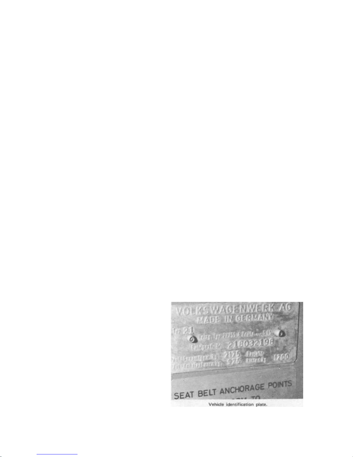
the engine number are known when a part is ordered. The chassis
number is to be found on a plate fitted to the panel alongside
the drivers seat (photo). The first two numbers of the chassis
number denote the basic type. For example '21' is the van, '22'
and '24' the Microbus in standard or de luxe versions, '23' the
Kombi, '26' the pick-up range and '27' is an ambulance. The
third figure denotes the model year. '8' for example is model
year 1968 which runs from August 1967 to July 1968. The
remaining digits are the serial numbers for the model year
changes.
The engine number is stamped on the engine crankcase below
the pedestal which supports the generator. It has one or two
prefix letters followed by a serial number. Prefix letters change
when there is a significant difference between engines. All
engines covered by this manual are the '1600' (1584 6c) version.
Engine prefix letters for this series are:—
'AS' August 1974 on - compression ratio 7.5 : 1
'B' - 47 bhp - early versions with or without exhaust emission
control systems
'AD' - 50 bhp - 1971 model year
'AE' the same as AD but with exhaust emission control
'AF' - low compression (6.6 : 1).
As far as the UK is concerned the main source of spares is the
VW dealer network. If they cannot supply you with what you
want immediately then it is most probably due to the fact that
they do not reckon on keeping large stocks for over the counter
sales, and although they may have one or two of what you need,
cannot afford to risk being out of stock for a customer who
brings his car in for repair. VW agents are very helpful but one
cannot blame them for this insistance on keeping a minimum
stock level for their own use. It applies particularly to the less
common items. So before tearing your vehicle to pieces check
the spares position at your VW agency; you could save yourself a
lot of trouble.
With gasket sets - for both engine and gearbox - do not be
alarmed if there seem to be many items included in the set you
buy, which do not fit your vehicle. To save a lot of variety of
kits they include in.one enough to cover a variety of types over a
period of time so you are certain to have some left over.
However, it is a good idea to check the set before leaving the
parts store. Some of the ones you may need could be omitted.
Oil seals particularly are not all included - and this applies to
some of the smaller ones. (Oil cooler).
Downloaded from www.Manualslib.com manuals search engine

Routine maintenance
For modifications, see Supplement at end of manual
Introduction
Because of the inherent toughness and reputation for
reliability and long life there is a tendency for owner s to be a bit
sketchy on VW maintenance - particularly with vehicles not in
the first flush of youth.
The VW will put up with neglect for a long time but when
the crunch eventually does come it is likely to be drastic.
Regular maintenance therefore, is just as important as on any
other vehicle.
The service procedures listed hereafter cover all the points of
required regular service. The frequency of service tends to vary
according to changes in design of various components, the conditions under which the vehicle is used, and the way in which it
is driven. The frequencies given are based on a mileage of 12000
per year in a temperate climate whicnis mainly non dusty.
Variations from this will be taken into account by VW service
agencies in different conditions. Variations in driving style must
be the responsibility of the driver where servicing requirements
could be affected.
Where maintenance is solely a matter of inspection (rather
than lubrication, cleaning or adjustment) the findings from such
inspections will determine whether or not further action is
required. Such further action is no longer within the scope of
Routine maintenance. It is a workshop procedure requiring
repair or renewal. How to do the maintenance is detailed after
the schedules. If the details are already in the main chapters then
reference is made appropriately.
A revised Maintenance Schedule based on a 'mileage covered'
frequency is included in Chapter 12 Supplement.
1 SAFETY MAINTENANCE
a) Steering tie rod ball joints - Check for wear 3 months
Steering gear - Check worm to roller play and worm shaft
bearings. Adjust if necessary 3 months
Front wheel bearings - Check end play and adjust if necessary
3 months
b) Branes
Hydraulic fluid reservoir level 1 month
Efficiency and foot pedal free play - Check and adjust as required 3 months
Handbrake efficiency - Check and adjust as required
Brake friction lining material - Check thickness 6 months
Hydraulic lines, hoses, master cylinder wheel cylinders and
calipers. Examine exteriors for leaks or corrosion 6 months
Renew all seals and fluid 3 years
NOTE: A significant drop in fluid reservoir level or any other
indication of fluid leakage is a danger signal. A complete and
thorough examination of the hydraulic system should be made.
c) Suspension
Tyres - Inflation pressure check Weekly
Tyres - Wear and damage check As suspect
Front torsion arm ball joints - Check for wear 3 months
Dampers - Check for leakage and malfunction 3 months
Vision
d)
c)
d)
Lights functioning (including direction and stop lights)
Screen washer operative
SAFETY MAINTENANCE PROCEDURES
Steering
See Chapter 10
Brakes
Hydraulic fluid reservoir level - The reservoir is mounted on
the vertical panel in the front of the cab
Top up to the indicated level with approved fluid as required.
Remaining items - See Chapter 8.
Suspension
See Chapter 10.
Vision
Lights - See Chapter 9.
Screen washer reservoir - The washer liquid reservoir is fitted
Downloaded from www.Manualslib.com manuals search engine
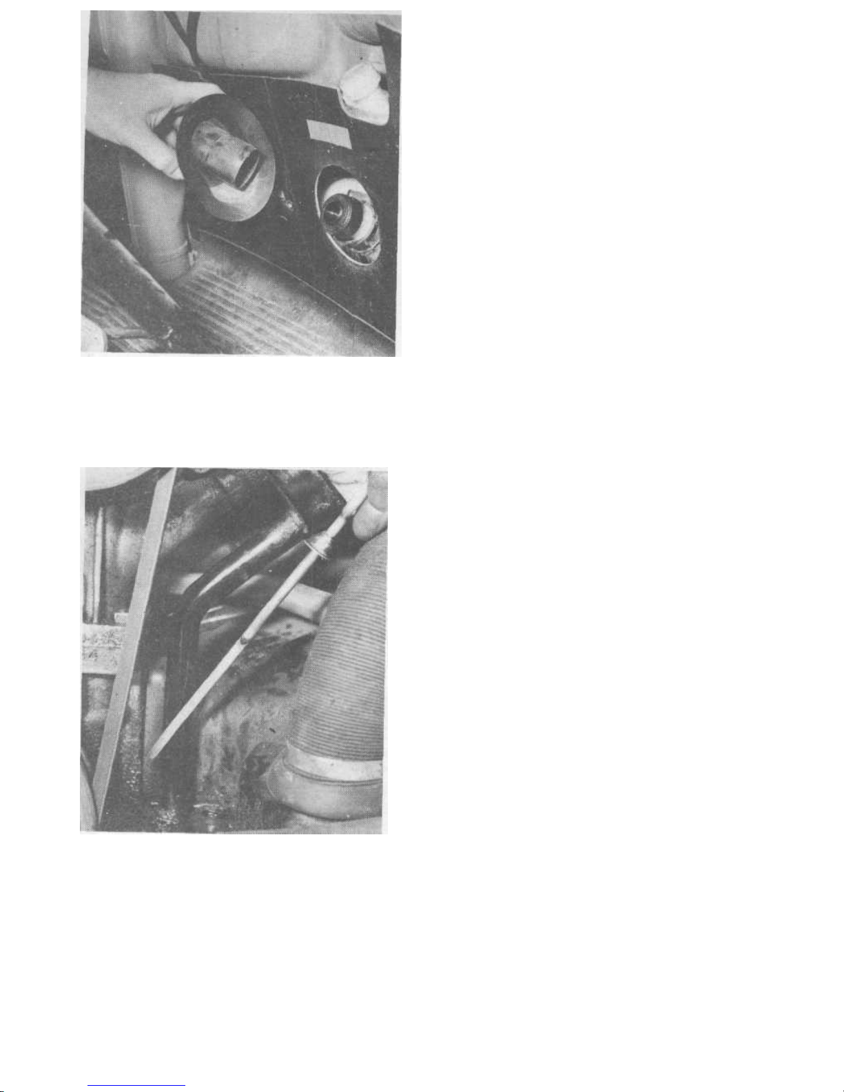
The windscreen washer reservoir is
mounted on the vertical panel in the
front of the cab just below the brake
fluid reservoir.
Engine oil dipstick.
to the front panel of the cab just below the hydraulic fluid
reservoir. It has a protective cover and tucked inside is a tube
with an ordinary tyre valve for pressurisation purposes (photo ).
The screen washer reservoir should be full of clean water with an additive of anti-smear compounds as wished. The tank
should be pressurised from an ordinary tyre inflator to the
maximum pressure of 42 psi/3 kg cm2 which is marked on the
tank.
If the jets do not direct water on to the screen as they
should, refer to Chapter 9 for details.
In the UK correctly functioning screen washers are a legally
required fitment to all cars.
3 EFFICIENCY AND PERFORMANCE MAINTENANCE
a) Engine
Lubricating oil - Top up to level Weekly
Lubricating oil - Drain, clean filter screen and refill with
Lubricating oil - fresh oil. 3 months
Fan belt - Check tension and adjust if required. 1 month
Air cleaner - Clean out bowl and refill with oil (oil bath
type). 3 months
Air cleaner - Renew paper element (paper element
type) 6 months
Air cleaner - Check correct operation of warm air
control flaps. 1 month
Battery - Check electrolyte level. Weekly
Distributor - Check contact points gap. Adjust
Distributor - and/or renew. 3 months
Distributor - Lubricate cam. 3 months
Valve clearances - Check and adjust as required
Valve clearances - (renew rocker cover gaskets). 6 months
Spark plugs - Removal clean and reset. 6 months
Spark plugs - Renew. 12 months
Fuel pump-Clean filter. 6 months
Carburettor - Check setting of throttle cable
Carburettor - and lubricate linkage. 6 months
Cover plates and fan housing - Check security of all screws
and grommets. 3 months
b) Suspension
Front wheel bearings - Repack with grease. 2 years
Rear wheel bearings - Repack with grease. 2 years
c) Transmission and final drive
Gearbox oil - Check level and top up as needed. 3 months
Gearbox oil - Drain and refill with fresh oil except type 091
manual gearbox (August 1975 on) which is 'filled for life'
2 years
Clutch pedal free play - Check movement and adjust.
As necessary
Axle shaft flexible gaiters - Check for splits 3 months
Renew charcoal filter (Fuel Evaporative System)
30 000 miles
4 EFFICIENCY AND PERFORMANCE MAINTENANCE
PROCEDURES
a) Engine
Lubricating oil.
To top up the oil, remove the filler cap from the filler pipe at
the right hand side of the engine. Remove the dipstick to prevent
possible blow back up the filler pipe when pouring oil in. A
suitable container or funnel is needed in order to add oil without
spillage. The top dipstick mark is the correct capacity level. The
lower mark is half full. Do not overfill or let the level drop
significantly below the full mark.
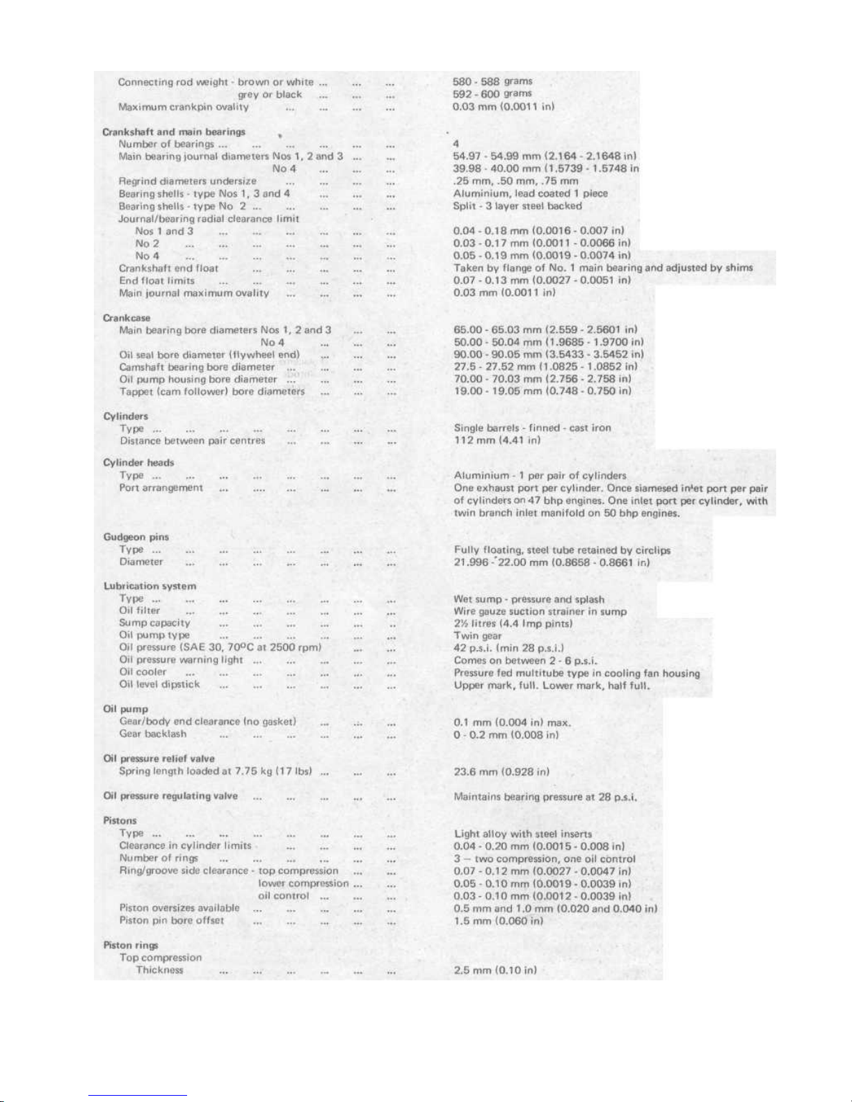
When changing the engine oil the filter screen - which is
simply wire gauze should be flushed out with paraffin to clear
the gauze. This entails removing the circular retaining plate
Downloaded from www.Manualslib.com manuals search engine
Routine maintenance
11
1
in the centre of the bottom of the crankcase. Before starting,
you must obtain two new gaskets for it, and it is also desirable to
get six new copper washers for the stud nuts.
First drain the oil by removing the centre plug and then
remove the cover plate. Take care when removing the strainer.
Do not distort it.
Later engines do not have the central plug so a suitably large
container will be needed to catch the oil as it leaks out when the
plate nuts are loosened.
The oil suction pipe which goes into the centre of the strainer
gauze must be quite firm. If it is loose then it is likely that
suction is being lost and the oil circulation is not 100% efficient.
(The engine needs completely stripping to put this right).
The strainer incorporates a relief valve in case the filter mesh
should get completely blocked up.
Having thoroughly cleaned everything refit the strainer with a
gasket on each side of the flange. See that the suction pipe is
properly located in the strainer Fit new copper washers
followed by the cap nuts. Do not overtighten the cap nuts -
otherwise the threads may strip.
Replace the drain plug and refill with 4V2 pints of approved
engine oil.
Fan belt - See Chapter 2.
Air cleaner - See Chapter 3.
Battery - See Chapter 9.
Distributor - See Chapter 4.
Valve clearances - See Chapter 1.
Spark plugs - See Chapter 4.
Fuel pump - See Chapter 3.
Carburettor - See Chapter 3.
b) Suspension
Front wheel bearings - See Chapter 10.
Rear wheel bearings - See Chapter 7.
c) Transmission and final drive
Gearbox oil - To check the level stand the vehicle on level
ground and undo the level plug which is halfway up the side of
the casing on the left - just ahead of the axle shafts. This plug is a
recessed hexagon which could be very difficult to undo.
Use a tubular spanner or bolt head which fits snugly. If the
plug is burred by makeshift methods it will get progressively
more difficult to adjust. Add oil from a suitable oil gun or
squeeze pack with flexible filler spout. Add oil slowly until it
runs out from the filler/level hole. Clean the plug and replace it
tightly.
When changing the transmission oil it is best to run it warm
first. Then undo the magnetic drain plug which is in the centre
of the casing at an angle at the rear Let the oil drain out for at
least 15 minutes. Clean the magnetic drain plug and replace it.
Before beginning to refill get the exact amount of oil needed
ready, and then start to fill up through the filler/level plug. It is
possible that oil will overflow before you have put it all in. Wait
so that the air pockets have time to bubble out and then
continue until all the oil is put in.
Clutch pedal free play - See Chapter 5.
Axle shaft gaiters - See Chapter 7.
Transmission magnetic oil level plug.
TYPICAL CHARCOAL CANISTER (FUEL EVAPORATIVE
SYSTEM) AIR CLEANER REMOVED FOR ACCESS
ENGINE OIL DRAIN PLATE AND FILTER GAUZE
Downloaded from www.Manualslib.com manuals search engine

General description and type identification ... ... ... 1
Repair and maintenance procedures - dismantling ... ... 2
Engine removal - preparation ... ... ... ... ... 3
Engine - removal ... ... ... ... ... ... 4
Engine dismantling - general ... ... ... ... ... 5
Engine ancilliaries - removal ... ... ... ... ... 6
Oil cooler - removal and renovation ... ... ... ... 7
Oil pressure relief and control valves- removal and renovation 8
Crankshaft pulley wheel - removal and replacement ... 9
Oil pump-removal and replacement ... ... ... ... 10
Cylinder heads - removal ... ... ... ... ... 11
Cylinder heads - dismantling and renovation of rocker gear,
valves and springs ... ... ... ... ... ... 12
Cylinders, pistons and rings - removal and renovation ... 13
Connecting rods and bearings - removal and renovation ... 14
Camshaft and tappets - removal and renovation ... ... 15
Flywheel - removal and renovation ... ... ... ... 16
Crankshaft oil seal - removal ... ..-> ... .. ... 17
Crankshaft and main bearings - removal and renovation ... 18
Distributor drive shaft - removal .. ... ... ... 19
Crankcase - examination and renovation ... ... ... 20
Engine reassembly - general ... ... ... ... 21
Crankshaft - asseambly of gears and main bearings ... 22
Connecting rods - assembly to crankshaft ... ... 23
Crankcase, crankshaft, camshaft and cam followers - reassembly ... ... ... ... ... ... ... 24
Pistons, rings and connecting rods - reassembly ... ... 25
Cylinders - replacement ... ... ... ... ... 26
Cylinder heads, valves and springs - reassembly ... .. 27
Cylinder heads - replacement ... ... ... ... 28
Rocker gear and pushrods - replacement ... ... ... 29
Crankshaft oil seal - replacement ... ... ... ... 30
Flywheel - replacement ... ... ... ... ... 31
Oil pump - replacement ... ... ... ... ... 32
Oil cooler - replacement ... ... ... ... ... 33
Valve to rocker clearances-adjustment ... ... ... 34
Engine - reassembly of ancilliaries ... ... ... ... 35
Engine - replacement and starting up ... ... ... 36
Fault finding ... ... ... ... ... 37
Specifications
Type
Weight
Bore ...
Stroke ... ...
Capacity
Compression ratio: To April '68 ...
From April '68
Power output (to August '70)
(from August '70) ...
Torque (to August '70)
(from August '70)
Compression pressure
Location of No 1 cylinder ...
Firing order ...
Engine mounting ...
Camshaft and camshaft bearings
Camshaft drive
Camshaft bearings
Camshaft journal diameters
Journal/bearing radial clearance
End float
Gear backlash
Connecting rods and bearings
Type .
Big end bearings
Crankpin (big end) diameter
Small end bush
Undersize big end shells available ...
Crankpin to bearing clearance limits
Crankpin end float ...
Gudgeon pin/bush radial clearance limits
Gudgeon pin diameter
4 cylinder, horizontally opposed flat, pushrod ohv
240 lbs/ 109 kgsapprox.
85.5 mm
69 mm
1584 cc
7.7:1
7.5:1
47 DIN bhpat 4000 rpm
50 Dl N bhp at 4000 rpm
82 Ib ft at 3000 rpm
81.7 Ib ft at 3000 rpm
114 - 142 psi (8.0- 10.0 kg cm 2)
Right hand front (nearest front of vehicle)
1 (R. Front) 4 (L. Rear) 3 (L. Front) 2 (R. Rear)
By cross member carrier and gearbox mountings.
Lightweight alloy gear direct from crankshaft
Steel backed white metal shells
24.99 - 25.00 mm (0.9837 - 0.9842 in)
0.02 - 0.12 mm (0.0008 - 0.0047 in)
0.04 - 0.16 mm (0.0016 - 0.0063 in)
0.00 - 0.05 mm (0.00 - 0.002 in)
Forged steel
3 layer thin-wall shells
54.98 - 55.00 mm (2.1644 - 2.1653 in)
Lead/bronze coated steel - pressed in.
0.25 mm, 0.50 mm, 0.75 mm.
0.02 - 0.15 mm (0.0008 - 0.006 in)
0.1 - 0.7 mm (0.004 - 0.028 in)
0.01 - 0.04 mm (0.0004 - 0.0016 in)
21.996 - 22 mm (0.8658 - 0.8661 in)
Chapter 1 Engine
For extra information, see Supplement at end of manual
Contents
Downloaded from www.Manualslib.com manuals search engine
Chapter 1/Engine
13
Downloaded from www.Manualslib.com manuals search engine
1 General description and type identification
The 1600 version of the established 'Beetle' engine was
introduced into the transporter range in 1967. The basic configuration of the 'Beetle' engine is unchanged - the cooling
system incorporating the superimposed type of fan and housing.
Modifications were made to the lubrication system by fitting an
additional spring loaded valve which maintains oil pressure at the
crankshaft bearings. In 1970 further modifications increased the
power output and at the same time the cooling system was
improved by fitting a larger capacity fan and moving the oil
cooler.
As a guide to identification the engines have prefix letters to
their 7 figure serial numbers. These numbers are to be found on
the crankcase at the base of the generator pedestal
B -47 bhp(DIN)
AD - 50 bhp (DIN) (1971 onwards)
AE - 50 bhp (DIN) - emission control
AF - Low compression 6.6 : 1
AS - August 1974 on - compression ratio 7.5 : 1
The engine is an air-cooled horizontally opposed flat four
Chapter 1/Engine
14
Downloaded from www.Manualslib.com manuals search engine
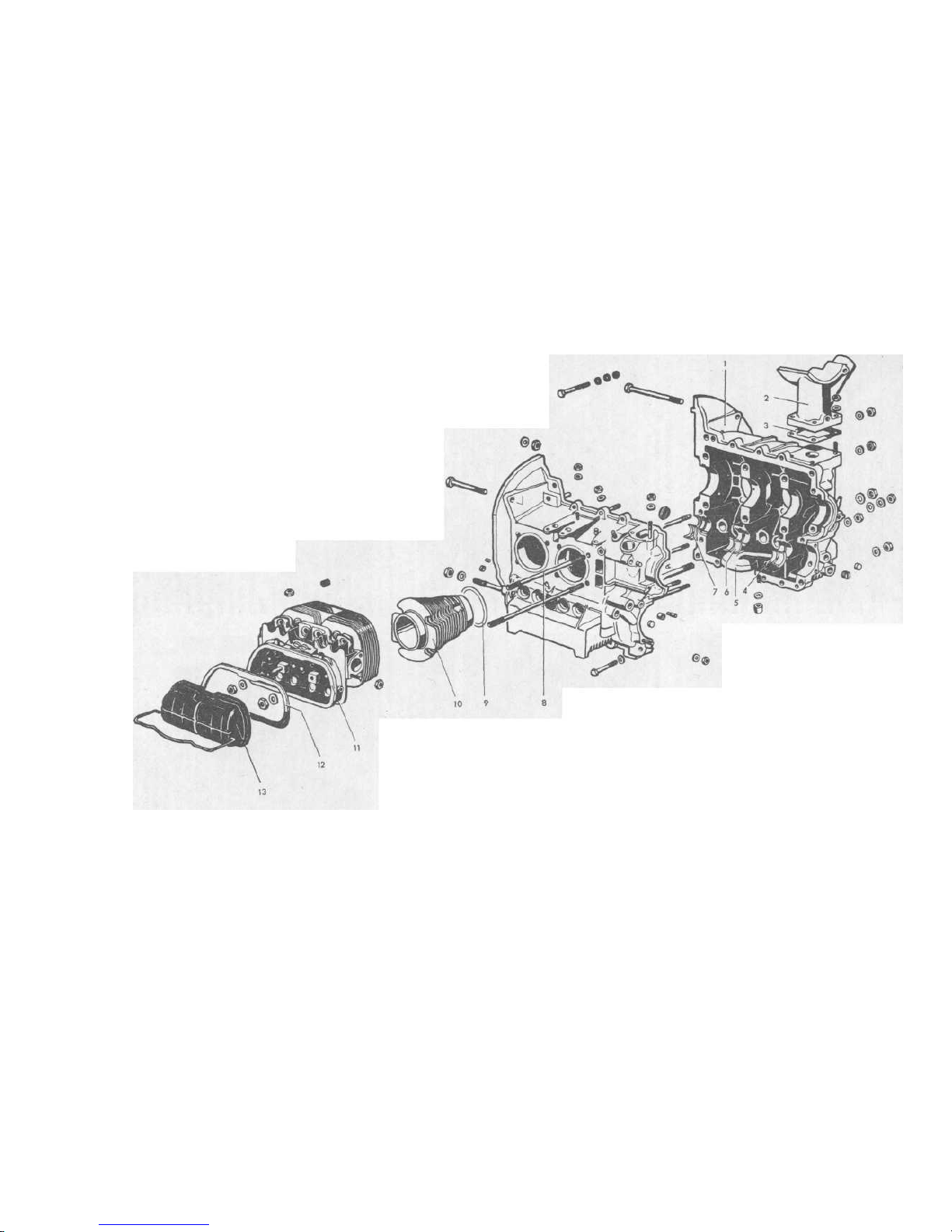
1 Crankcase - right half
2 Generator pedestal
3 Gasket
4 Camshaft bearing - shell -
rear
5 Oil selec tor pipe
FIG.1.1 ENGINE STATIC PARTS • EXPLODED VIEW
6 Camshaft bearing shell- front gasket
centre 8 Cylinder head stud 10 Cylinder barrel
7 Camshaft bearing shell - front 9 Cylinder base sealing 11 Cylinder head
12 Rocket cover
gasket
13 Rocker cover
Downloaded from www.Manualslib.com manuals search engine

16
Chapter 1/Engine
cylinder design. The short crankshaft runs in aluminium alloy
shell bearings located between the two halves of a magnesium
alloy crankcase which join vertically. The camshaft runs
centrally below the crankshaft and is gear driven from the rear
end of the crankshaft. The camshaft is also located between the
crankcase halves and runs in removable split shell bearings.
The distributor is driven by a removable shaft from a gear
mounted on the rear end of the crankshaft. The same shaft
incorporates a cam which operates the fuel pump operating
plunger rod.
The gear type oil pump is mounted in the rear of the crankcase, held between the two halves and driven by a horizontal
shaft. A tongue on the inner end of the shaft engages in a slot in
the end of the camshaft.
Four finned cylinder barrels are separately mounted and
each pair has a common cylinder head containing the valves
and rocker gear. The pushrods locate in cylindrical flat faced
cam followers at the camshaft end and pass through sealed
cylindrical tubes clampedbetween the head and crankcase outside
the cylinder barrels. Each rocker cover is held to the head by
spring hoops locating in a recess in the cover.
The flywheel is located on the front of the crankshaft by
four dowel pegs and secured by a single central bolt which also
incorporates needle roller bearings for the gearbox input shaft.
The front crankcase oil seal bears on the centre hub land of the
flywheel. The rear end of the crankshaft has an oil thrower plate
and a helical groove machined in the pulley wheel hub to contain
the oil. An oil filter screen is mounted in the bottom centre of
the crankcase apd the oil suction pipe for the pump comes from
the centre of it. There is no other form of oil filter incorporated.
The generator, which is mounted on a pedestal above the engine,
is driven by a V-belt from the crankshaft pulley. On the forward
end of the generator shaft the cooling fan is mounted. This runs
in a sheet steel housing which ducts air down to the cylinder
barrels.
There is no separate oil sump - the crankcase acting as an oil
reservoir of just under 4V4 pints.
Engine cooling is regulated by a bellows type thermostat
which is mounted in the air flow under the right hand pair of
cylinders. The thermostat operates two linked control flaps in
the fan housing lower ducting section at left and right.
The car heating system is integral with the engine cooling and
is achieved by directing arm through ducts which shroud the
exhaust pipes. Two flexible ducts lead from the fan housing to
the heat exchangers - and then via two more ducts to the car
interior.
The cooling system also incorporates an oil cooler which is a
multi-tube heat exchanger mounted vertically on the crankcase. Air from the cooling fan is ducted past it.
2 Repair and maintenance procedure - dismantling
Apart from routine servicing and checking or replacement of
ancilliary components no attempt should be made to carry out
engine repairs with the engine in the vehicle.
The removal and overhaul of the ancilliary components are
dealt with in the appropriate chapter (where illustrations will
also be found). The following list gives an idea of what can be
removed or repaired with the engine still in the vehicle.
Oil pressure relief and control valves - Chapter 1
Thermostat bellows Chapter 2
Exhaust manifold - Chapter 2
Fan/generator assembly - Chapter 2
Carburettor - Chapter 3
Fuel pump - Chapter 3
Inlet manifold - Chapter 3
Distributor - Chapter 4
Distributor drive shaft - Chapter 4
Coil -Chapter 4
Generator (with fan) -Chapter 10
Starter motor - Chapter 10
3 Engine removal - preparation
Removal of the engine is straightforward enough provided
there are proper metric tools available - or their nearest A.F.
equivalents which are a satisfactory fit for many of the larger
size requirements.
If a crane capable of lifting the rear of the vehicle is available
the engine may be removed from underneath by disconnecting it
after supporting it on a trolley jack, lifting the vehicle away from
the engine and then lowering the engine to the ground and
withdrawing it to the rear. However, the vehicle weighs just
under a ton. The necessity of lifting it can be avoided by
rernoving the rear engine compartment cross panel and the rear
bumper. The engine can then be supported on a trolley jack,
disconnected, and withdrawn to the rear while the vehicle
remains on its road wheels. Do not try makeshift methods, the
engine weighs 240 lbs and the engine casing is both fragile and
expensive. This removal is discussed in detail in Section 4 of this
chapter.
If the vehicle is very dirty underneath it would be well
worthwhile getting it thoroughly cleaned off away from the
removal area first. The lower mounting stud nuts are exposed to
the elements and the top bolts and nuts call for a certain amount
of reaching around. If you are working on your back at floor
level, dirt falling in the eyes can be a major irritation.
It is possible to get the engine out and clear single-handed if
all the equipment is available but the trickiest part is lowering
theengine to floor level. Assistance is insurance against dropping
it. Even a few inches fall could crack the aluminium crankcase there being no conventional sump. Note that the engine is
back-to-front as compared with a conventional layout so that the
flywheel is nearer the front of the vehicle. All references to
front and rear of the engine will, therefore, be in relation to its
position in the car.
4 Engine - removal
1 Stand the vehicle on a hard level surface with sufficient room
at the rear to draw the engine back. The wheels should be raised
about 5 inches on blocks as this will give complete clearance in
the opening in the rear when the engine is pulled back.
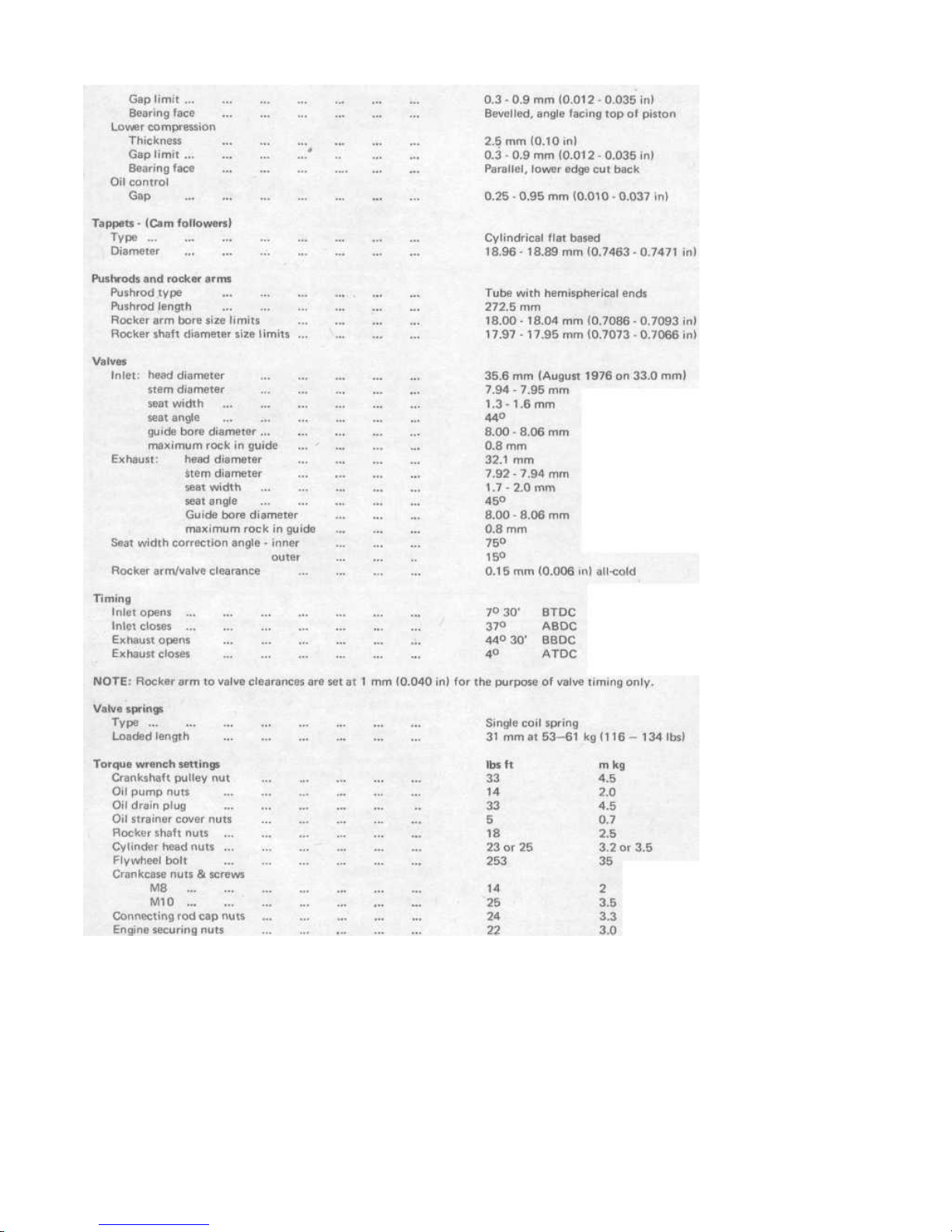
2 Disconnect the battery. Now is the time to drain the engine
oil; whilst the ancilliaries are being disconnected as described
next.
3 Remove the carburettor air cleaner by undoing the hose
securing clip at the carburettor end of the intake pipe, pulling
the other hoses off their connections, and releasing the three
securing clips holding the cleaner to the support bracket. On
earlier models disconnect the wire control cable to the air intake
flap. Do not tilt the cleaner too much or the oil will drip out.
4 Disconnect the accelerator cable from the carburettor by
undoing the clamp screw and drawing the cable out.
5 Detach two cables from the generator, one from the coil
(from the side of the engine compartment), one from the oil
pressure switch and two from the automatic choke and the cutoff valve of the carburettor. Tuck them out of the way to one
side.
6 Remove the compartment cross panel by undoing the screws
Qn the compartment floor and the bolts from the panel behind
the bumper. Pull the rubber weatherstrip out of the groove and
then lift the panel out (photo). On later models, the cross panel
is of different design and is not detachable.
7 Remove the engine upper securing nuts and bolts. They are
behind (infront of!) the fan housing and the nut is at the end of
the bolt on the right hand side. On the left hand side there may
be a nut too, but some models have a bolt which screws into a
threaded lug in the casting and this can only be undone from the
other side underneath. Under normal circumstances the bolt
heads are captive and will not turn when the nuts are undone.
8 Now get underneath. Pull off the flexible fuel pipe (from the
engine end, not the tank end) and clamp it with a self grip or
Downloaded from www.Manualslib.com manuals search engine
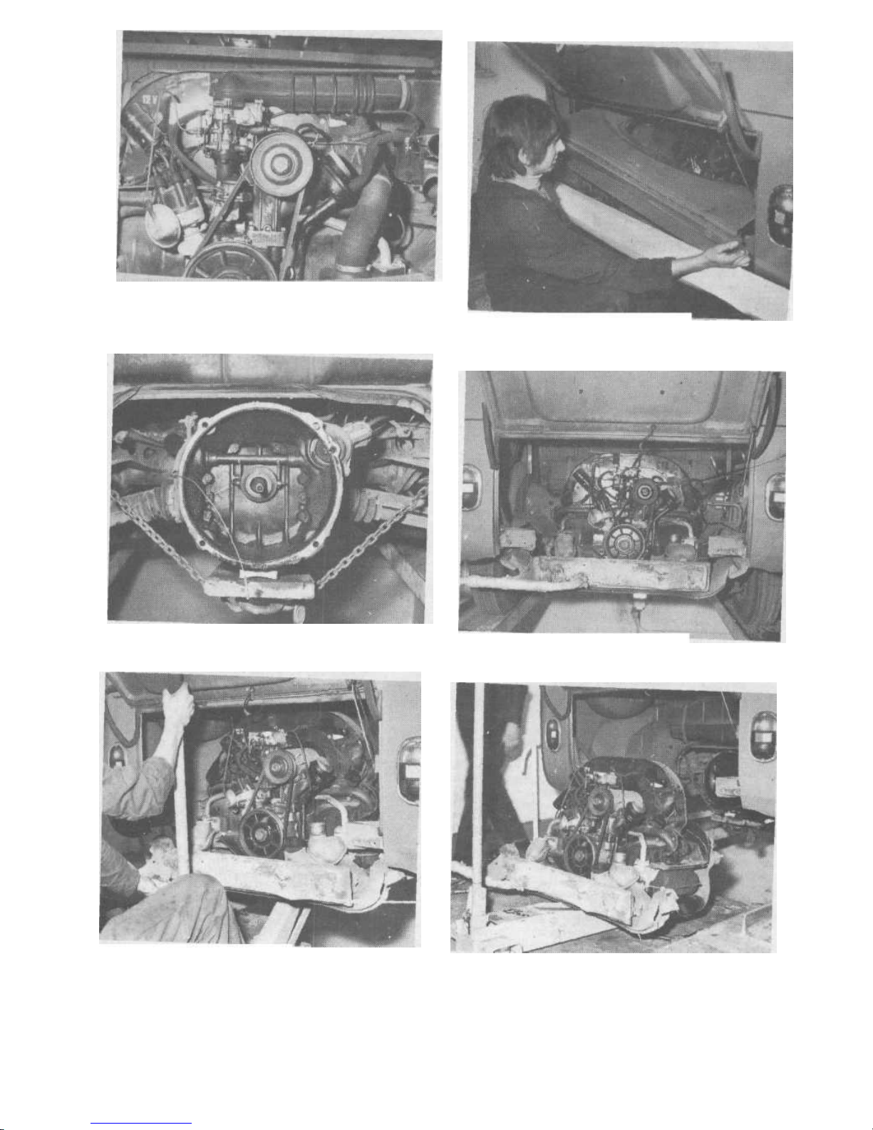
4.1 Open the engine cover and have a good look round.
4.6 Removing the cross panel (early modelsT
4.12 Support the gearbox with a piece of rope or cha.n Note th
wooden packing piece.
4.16 V,ew of the bumper with bumper and cr
4.18A Removing the engine on a trolley
jack
4.18B Engine lowered to the floor.
Downloaded from www.Manualslib.com manuals search engine

18
Chapter 1 /Engine
plug it with a pencil or punch. Fuel is gravity fed.
9 Pull off the heater pipe connection hoses.
10 Disconnect the heater flap cables.
11 Pull the accelerator cable through the fan housing.
12 Support the gearbox with a piece of rope, wire or chain slung
from the body side members under the floor. Do not support it
on a jack as you may wish to move the vehicle afterwards.
Support the gearbox to the rear of the drive shafts (photo).
14 Remove the lower engine securing nuts (photo).
15 If the left hand top bolt is one which screws direct into the
crankcase remove it now.
16 Remove the two large bolts holding the rear bumper brackets
to the side rails. Then take out the two bolts at each side
securing the valances to the wing panel. The upper ones are
fitted into captive nuts on the bumper valance. The lower ones
are small nuts and bolts which will be almost certainly rusted
solid and have to be cut off. Pull out the bumper (photo).
17 Remove the lower engine mounting bolt from each end of
the engine support bracket (photo).
18 Place the trolley jack with the head under the centre of the
crankcase and lift the engine a fraction to take the weight. It will
then have to be pulled back about 4 inches so as to draw the
clutch assembly off the gearbox input shaft and also to clear the
rear engine mounting brackets. This may call for some rocking
from side to side to achieve. When the engine is clear of the
gearbox and the mountings lower it and draw it out from the
rear (photos).
5 Engine dismantling-general
1 Unlike the majority of conventional engines the Volkswagen
is one which does not make it easy to carry out most tasks with
the engine still in the car. In view of the relative ease with which
it can be taken out and lifted on to a bench this manual does not
recommend that engine repair work of any significance is carried
out with the engine still in the vehicle. If you have a pit or ramp
that enables you to work conveniently under the car there are
instances when it is justifiable. Otherwise the inconvenient 'flat
on your back' method is tar too risky in view of the likelihood
of dirt getting into the wrong places and mistakes occurring.
2 For an engine which is obviously in need of a complete
overhaul the economies against a replacement engine must also
be carefully considered. The dismantling and reassembly of a
Volkswagen engine is more complex than for a normal four
cylinder block. Each cylinder is separate and the crankshaft and
camshaft run in bearings mounted between the two halves of a
precision faced, split crankcase. The number of individual parts
is far greater. It is not our intention to put you off - far from it but we must, in fairness to the owner, point out that it is much
easier to make an assembly mistake than on a conventional
engine.
3 The dismantling, inspection, repair and reassembly as
described in this Chapter follows the procedure as for a complete
overhaul.
4 Before starting work on any part it is strongly recommended
that time is spent in first reading the whole Chapter. It would be
too cumbersome and confusing to cross reference the implications of each and every activity. So if you think that the big
end bearings are your problem, for example, do not think that
by turning to the heading 'Big end bearings' all the implications
of repairing them will be contained in that single section.
Mention will be made in brief of the operations necessary which
may lead up to it and the details of these should be read first.
5 Whatever degree of dismantling is carried out, components
can only be examined properly after they have been thoroughly
cleaned. This is best carried out using paraffin and a stiff bristled
brush. Some engines can be particularly bad, with a stubborn
coating of hard sludgy deposits - generally denoting neglect of
regular oil changing - and it can take some time and effort to get
this off. Afterwards, the paraffin can be hosed off with a water
jet. Cleaning may sometimes seem to take a disproportionate
amount of time but there is no doubt that it is time well spent.
6 Engine ancillaries - removal
Having removed the engine from the car it may be assumed
that all the tinware will have to come off before any major
overhauls are carried out. Once the fan housing assembly is
removed together with the manifolds and heat exchangers and
the support beam (photo), the dismantling of the other
components is dealt with in this Chapter.
7 Oil cooler - removal and renovation
1 Remove the fan housing (Chapter 2).
2 The oil cooler is either mounted direct onto the crankcase or
by means of an adaptor, depending on whether it is a 1970 or
1971 model.
3 In the case of the former undo the one upper and two lower
nuts securing the cooler. In the latter case undo the nuts securing
it to the adaptor.
4 It will be fairly obvious if the cooler leaks severely but if
there is no apparent damage it may be difficult to decide
whether it functions correctly. If suspect it should be subjected
to a pressure test by a Volkswagen agent with the proper equipment. If there is any doubt about it the only sure remedy is a
new one. If the cooler is found to be leaking the oil pressure
relief valve should also be checked as it could have caused the
failure of the cooler.
5 It is rare for the fins of the cooler to get clogged up but if
they have, soak them in a solvent such as 'Gunk' and then flush
and blow them through with a high pressure air line. Do not try
and poke dirt out with sharp pointed implements.
8 Oil pressure relief and control valves - removal and renovation
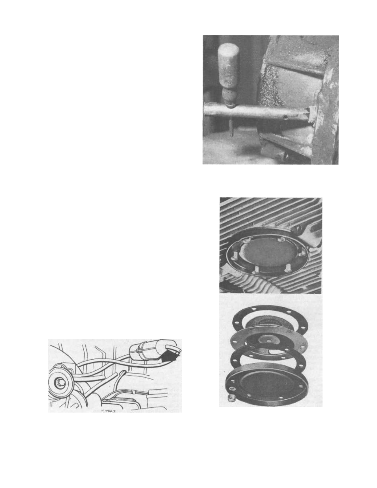
1 These may be removed from underneath with the engine in
the car. They are spring loaded pistons held into the left hand
half of the crankcase at front and rear by large screw plugs
(photo).
2 It is not necessary to drain the engine oil but be prepared to
catch a small quantity when either of the valves is removed.
3 When the plugs are removed the springs and plungers should
drop out. If a plunger sticks in the bore in the crankcase it may
need a little assistance and poking with a screwdriver.
4 If a piston seems seized and will not move it may be
necessary to start the engine. Oil pressure should blow it out.
Such drastic action being necessary would indicate serious
neglect in the matter of regular oil changes. Note that the
plungers and springs are not interchangeable so do not mix them
up (photo).
5 Both pistons should be a sliding fit in the crankcase bores.
Minor signs of seizure may be cleaned up. If there is severe
scoring in the piston it may be renewed but if the crankcase bore
is damaged the consequences could be serious and expensive,
calling for a new one also.
6 The larger of the two springs is for the oil pressure relief valve
and goes into the rear bore near the oil pump (photo). The
shorter spring is for the pressure regulating valve and goes into
the front bore near the transmission mounting (photo).
7 When refitting ensure that the springs locate in their recesses
in both piston and plug and that a new plug seal is used. The
relief valve serves to relieve excessive oil pressure from the oil
cooler when the oil is cold and thick. The regulating valve serves
to maintain oil pressure at the crankshaft bearings when the oil is
hot and thin.
9 Crankshaft pulley wheel - removal and replacement
1 Take off the cover plate held by three screws.
2 The pulley wheel is a straight keyed fit on the end of the
crankshaft. It is secured by a single, central bolt. To lock the
Downloaded from www.Manualslib.com manuals search engine
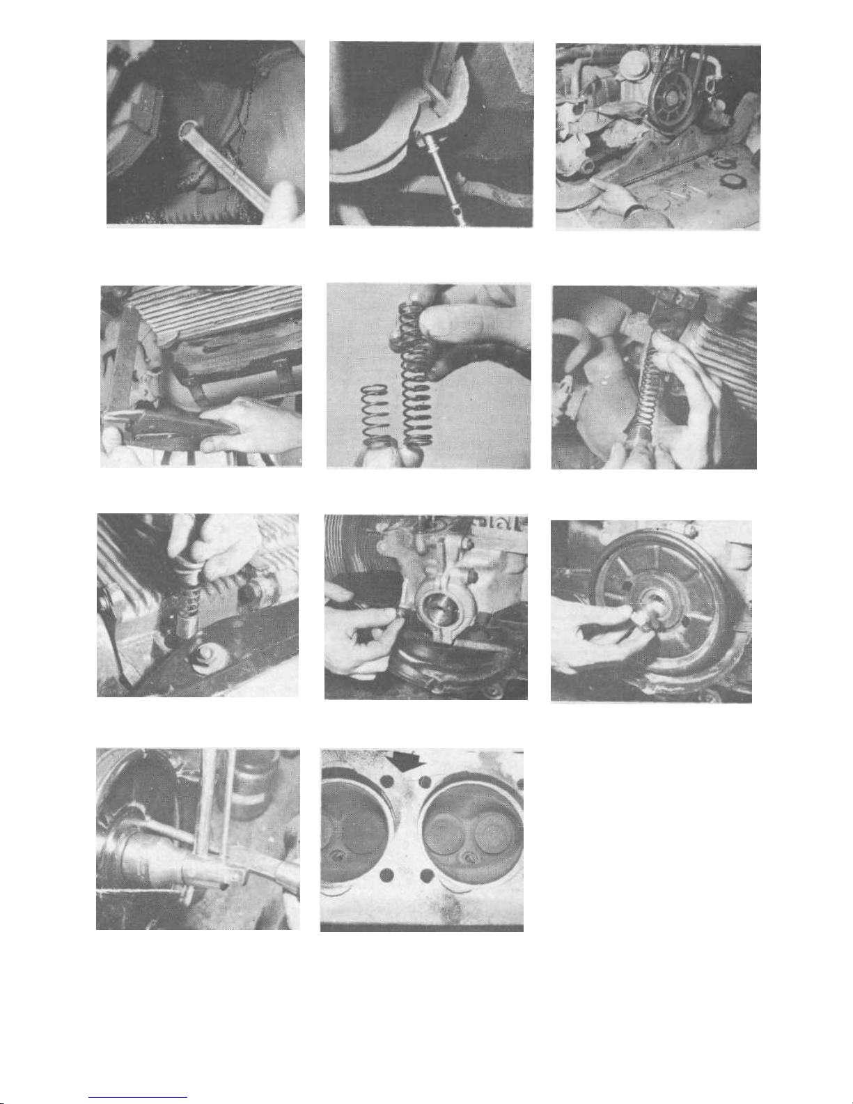
4.14 Remove the engine securing nuts
4.17 Removing one of the lower engine
mounting bolts - do not forget the other
one
6.1 Removing engine rear support beam
8.1 Undo stubborn oil pressure regulator 8.4 The relief valve spring is longer than 8.6a Replacing the relief valve piston
plugs with an improvised screwdriver. the regulator valve spring. spring and plug.
8.6b Replacing the regulator valve piston, 9.3 Fitting the lower cover before the 9 4a Replace the pulley nut
spring, and plug. crankshaft pulley.
9.4b Tighten the pulley nut. 12.6 The head to cylinder joint has been
'blowing', probably due to the stud not
having been tightened down properly.
Downloaded from www.Manualslib.com manuals search engine

20
Chapter 1 /Engine
pulley when undoing or tightening the bolt push a suitable
article through one of the holes in the pulley and jam it against
the crankcase flange.
3 If, when the nut has been removed, the pulley is a very tight
fit, do not apply force at the edges or you are likely to distort it.
Soak the boss with penetrating oil and hook something through
the two holes if any leverage is necessary.
4 If the pulley has been removed during the course of an overhaul remember that the lower rear engine plate has to be re-fixed
before the pulley (photo). There is no access to the two securing
screws after the pulley is in position.
5 The nut should be tightened to a torque of 33 ft/lbs when
the pulley has been replaced (photos), and Fig.1.5.
10 Oil pump - removal and renovation
1 Remove the crankshaft pulley wheel and the lower rear cover
plate.
2 The oil pump gears may be removed relatively easily because
once the oil pump cover plate has been released by removing the
four retaining nuts, the gears may be drawn out of the pump
body.
3 The pump body itself is mounted over the same four studs as
the cover plate and is clamped between the two halves of the
crankcase. To remove the pump body from the engine without
splitting the crankcase is best done with a special tool which fits
over the studs, locks to the inside of the body and draws it out.
If you do not have such a tool then the best way is first to
slacken the crankcase clamping stud nuts above and below the
pump. This relieves the pressure on the body. A suitable tool can
then be tapped against the edge of the pump body and, in easy
stages, it can be eased out over the studs. Do not force a tool
into the gap between the pump body and the crankcase as this
could damage the mating faces and upset the correct alignment
of the pump on replacement.
If the crankcase is to be split anyway leave the pump body to
be taken out then.
4 It is possible to check the pump fairly comprehensively
without removing the body from the crankcase but it is, of
course, far less convenient and liable to cause measurement
inaccuracies.
5 First check the cover plate. If it is very badly scored it should
be renewed anyway. Light scoring can be ground out using
carborundum paste on a piece of plate glass.
6 Check that the driving spindle is a good fit in che body. Any
apparent rocking indicates that the inside of the pump body
must also be worn. The driven gear spindle should be tight in the
body. The gear should be a good fit on it with no play.
7 Provided both gear spindles are in good shape refit the gears
and measure the end clearance between them and the end of the
pump body. This is done by putting a straight edge across the
body and using a feeler gauge to measure the gap between the
straight edge an the gears (See Fig.1.4). Make sure no traces of
gasket remain on the flange of the body when doing this. The
gap should not exceed 0.1 mm (0 004 inch) or inadequate oil
pressure will result. The wear is most likely to be in the pump
body in this case and this will need renewal.
11 Cylinder heads - removal
1 Take the engine out of the car
2 Remove the exhaust system, heat exchangers and upper
cylinder cover plates as described in the Fuel and Cooling
Chapters. The inlet manifold together with carburettor should
also be taken off. See the Fuel system Chapter for details.
3 Prise off the spring clip, downwards, which clamps the rocker
cover to the head. Take off the cover.
4 Undo the two nuts, evenly, which secure the rocker shaft
pedestals and then pull off the pedestals, shaft and rockers as a
complete assembly. Pull out the four pushrods and push them
through a piece of cardboard so that the location of each one is
known and which is the top and bottom end.
5 Before starting to undo the eight nuts which hold the
cylinder head down onto the cylinder barrels it must be
appreciated that when the head is released the four pushrod
tubes will be freed and the cylinder barrels also. If the cylinder
barrels are not being taken off the pistons they will rest in
position but the engine must not be turned. If the engine is to be
turned the barrels should be temporarily tied down to the crankcase with string or wire. If the barrels are disturbed then they
must be removed so that new cylinder base gaskets may be fitted
(See Section 26).
6 Using a socket spanner, the cylinder head stud nuts should be
slackened % to 54 turn each only, in the reverse order of the final
tightening sequence as given in Fig.1.12. Continue releasing each
nut a little at a time until they are all slack. When all are
removed the head may be drawn back a little way.
7 Remove the pushrod tubes from between the head and crankcase and make sure the cylinders are disengaged from the head
before pulling the head right off.
12 Cylinder heads - dismantling and renovation of rocker gear,
valves and springs
1 To remove the rocker arms from the shaft the spring clips at
each end should be removed and the thrust washers and wave
washers taken off. The end rockers may then be removed. The
rocker shaft support pedestals may need tapping off if they are
tight in order to remove the two inner rocker arms, clips and
washers. If possible lay out the parts in the order in which they
were dismantled in a place where they need not be disturbed.
2 To remove the valves it is necessary to use a proper tool to
compress the valve springs. The tops of the springs are almost
level with the edge of the head casting. If you are unable to
obtain a G clamp with extended ends (to clear the edge of the
head when the spring is compressed) it will be necessary to use a
short piece of tube, with an aperture cut in the side, in con-
junction with a conventional spring compressor. The aperture is
to enable one to get at the.split collets on the valve stem.
3 Compress the spring using the clamp and if the tubular spacer
is being used make sure that the pressure is applied squarely and
that the tube cannot slip. As soon as the two split conical collars
round the valve stem are revealed, use a small screwdriver
through the aperture to hook them off the valve stem. It is
advisable to maintain one's hold on the spring clamp while doing
this to prevent anything from slipping. When the collets are clear
release the spring clamp.
4 The spring retainer collar and spring may then be lifted off.
There may be small sealing rings round the valve stems and these
too should be taken off. The valve can now be pushed through
the guide and taken out. If it tends to stick then it will be
because of carbon or sludge deposits on the end of the valve
stems and these should be cleaned off as necessary. The end of
the valve stem could also be burred due to the 'hammering'
action of the rocker arm; in which case the burrs should be
carefully stoned off. Do not force a tight valve through the guide
or you will score the guide. Keep valves in order so that they
may be replaced in the same port. Push them through a
numbered piece of cardboard to avoid getting them mixed up.
5 After the cylinder head has been removed and the valves
taken out, the head itself should be thoroughly cleaned of
carbon in the combustion chamber and examined for cracks. If
there are any visible cracks the head should be scrapped. Cracks
are most likely to occur round the valve seats or spark plug
holes. Bearing in mind that one head will cost (new) nearly 20%
of the cost of a complete replacement engine economies should
be considered as well as the likelihood of obtaining a used head
from a breaker's yard. If the latter, make sure that the head you
get is the same type as the old one - and in better condition!
6 Occasions occur when the head has been removed because of
'blowing' between the head and cylinder (photo). This is usually
caused when head studs and nuts have not been tightened to the
correct torque or tightened unevenly. Provided there are no signs
Downloaded from www.Manualslib.com manuals search engine
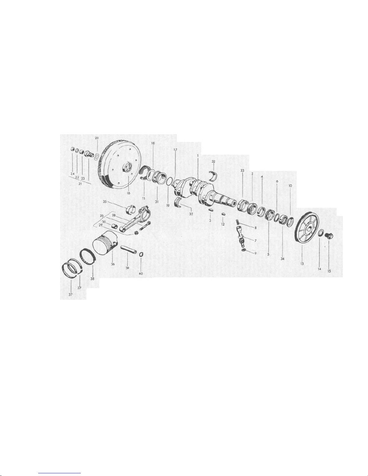
7 Crankshaft
2 Crankshaft gear
3 Woodruff key
4 Spacer
5 Distributor drive
6 Securing ring
7 Distributor drive
FIG.1.2 ENGINE RUNNING PARTS - EXPLODED VIEW
shaft
8 Spring
9 Washer
10 Oil baffle washer
11 Oil seal
12 Key for pulley
13 Crankshaft pulley
14 Washer
15 Bolt
16 Flywheel
17 Dowel
18 Spacer
19 Locking washer
20 Locking washer
21 Hollow bolt with
needle roller bearing
22 Sealing washer
23 Needle roller
bearing
24 Collar
26
Con
rod
28 Con rod screw
29 Nut
30 Small end bush
31 Main bearing
32 Bearing shell
33 Main bearing
34 Bearing shell
35 Big end bearing
shell
36 Piston
37 Piston ring
38 Scraper ring
39 Gudgeon pin
40 Circlip
IO
Downloaded from www.Manualslib.com manuals search engine

22
Chapter 1/Engine
of severe burning at the sealing area in the head then the cylinder
can be lightly ground in with carborundum paste. However, it
should be understood that the depth to the mating face for each
cylinder should be equal (give or take 3 to 4 thousandths of an
inch) otherwise the head will not seat level on both cylinder
barrels and leaks will recur. If both parts of the head are ground
equally to level things up remember that you will have to check
piston clearance and that you will also have raised the compression ratio. Facilities do exist (in Germany anyway!) for
reconditioning cylinder heads and fitting aluminium shims of
0.8, 1.0 or 1.5 mm thickness as necessary. In exchange engines 1
mm steel shims are fitted as standard on reconditioned heads,
but these are not available as spares.
7 The valve seats should be examined for signs of burning away
or pitting and ridging. If there is slight pitting the refacing of the
seats by grinding in the valve with carborundum paste will
probably cure the problem. If the seat needs re-cutting, due to
severe pitting, then the seat width should not exceed
specification (see Fig.1.7). Fitting new valve seat inserts is a
specialist task as they are chilled and shrunk in order to fit them.
Check with the nearest Volkswagen dealer because you could
have difficulty in getting this problem solved cheaply.
8 The rocker gear should be dismantled and thoroughly cleaned
of the sludge deposits which normally tend to accumulate on it.
The rocker arms should be a smooth fit on the shaft with no
play. If there is any play it is up to the owner to decide whether
it is worth the cost of renewal. The effects on engine performance and noise may not be serious although wear tends to
accelerate once it is started. The valve clearance adjusting screws
should also be examined. The domed ends that bear on the valve
stems tend to get hammered out of shape. If bad, replacement is
relatively cheap and easy.
9 The valves themselves must be thoroughly cleaned of carbon.
The head should be completely free of cracks or pitting and
must be perfectly circular. The edge which seats into the
cylinder head should also be unpitted and unridged although
very minor blemishes may be ground out when re-seating the
valve face.
10 Replace the valve into its guide in the head and note if there
is any sideways movement which denotes wear between the stem
and guide. Here again the degree of wear can vary, if excessive,
the performance of the engine can be noticeably affected and oil
consumption increased. The maximum tolerable sideways rock,
measured at the valve head with the end of the valve stem flush
with the end of the guide, is 0.8 mm (0.031 inch). Wear is
normally in the guide rather than on the valve stem but check a
new valve in the guide if possible first. Valve guide renewal is a
tricky operation in these cylinder heads and you may find it
difficult to get it done. Check with the nearest Volkswagen
dealer first. Do not attempt it yourself. One final part of the
examination involves the end of the valve stem where the rocker
arm bears. It should be flat but often gets 'hammered' into a
concave shape or ridged. Special caps are available to put over
the ends. Alternatively, the ends can be ground off flat with a
fine oil stone. Remember that it is difficult to set the valve
clearances accurately with the adjusting screw and valve stem in
a battered condition.
13 Cylinders, pistons and rings - removal and renovation
1 The cylinders may be removed, after the cylinder heads are
off, simply by drawing them from over the pistons. Mark which
cylinder comes from where first Make sure that the piston and
rings are not damaged after the cylinder has been removed. It
must also be remembered that if the crankshaft is turned after
removing the cylinder the piston skirts can foul the crankcase
unless they are guided at the bottom of the stroke.
2 The piston rings may be removed from the pistons by carefully spreading the ends of each ring so that it comes out of its
groove and then drawing it off over the top of the piston.
3 To remove the piston it is necessary to separate it from the
connecting rod as it is not possible to get at the connecting rod
bolts with the piston fitted.
4 Remove the circlip from one side of the piston boss where
the gudgeon pin is retained and it will be possible to push out
the .gudgeon pin. If it resists then warm up the piston with an
electric light bulb held next to it for a while. Do not try and
drive out the gudgeon pin from a cold piston. You will possibly
bend a connecting rod. It is only necessary to push out the pin
far enough to enable the connecting rod to be released from the
piston. If the pistons are to be put back make sure that each one
is marked suitably so that you know (a) which number cylinder
it came from and (b) which way faces forward. A good way is to
scratch the number and an arrow, pointing forward, on the
crown before removal. If you do make a nonsense and forget
how it came off then carefully clean the top of the crown and
look for identifying marks which indicate the front or flywheel
side. Volkswagen pistons are stamped with an arrow at the edge
of the crown pointing towards the flywheel. British made pistons
have the word 'flywheel' stamped on in that position.
5 Piston and cylinder bore wear are contributory factors to
excessive oil consumption (over 1 pint to 300 miles) and general
engine noise. They also affect engine power output due to loss of
compression. If you have been able to check the individual
cylinder pressures before dismantling so much the better. They
will indicate whether one or more is losing compression which
may be due to cylinders and pistons if the valves are satisfactory.
6 The piston rings should be removed from the pistons first by
carefully spreading the open ends and easing them from their
grooves over the crown of the piston. Each one should then be
pushed into the cylinder bore from the bottom using the head of
the piston to make sure they rest square in position about 5 mm
from the bottom edge. The gap between the ends of the ring can
then be measured with a feeler gauge. For the two compression
rings it should not exceed 0.90 mm (0.035 inch) and for the oil
scraper ring 0.95 mm (0.037 inch). If the gaps are greater you
know that new rings at least are required.
7 Determining the degree of wear on pistons and cylinders is
complementary. In some circumstances the pistons alone may
need renewal - the cylinders not needing reboring. If the
cylinders need reboring then new pistons must be fitted. First
check the cylinders.A preliminary check can be done simply by
feeling the inside walls about JS inch down from the top edge. If
a ridge can be felt at any point then the bores should be
measured with an inside micrometer or calipers to see how far
they vary from standard. The measurement should be taken
across the bore of the cylinder about 15 mm (0.6 inch) down
from the top edge at right angles to the axis of the gudgeon pin.
Then measure the piston, also at right angles to the gudgeon pin
across the skirt at the bottom. The two measurements should
not differ by more than 0.20 mm (0.008 inch).
8 Further measurement of the cylinder across the bore will
indicate whether or not the wear is mostly on the piston. If the
cylinder bore is uniform in size fitting new pistons alone is
possible. However, it is a very short sighted policy. If new
pistons are needed anyway the cost or reboring will add 20-25%
to the cost of the pistons so it would be as well to get it done
whilst the cylinders are off.
9 Another feature of the pistons to check is the piston ring side
clearance in the grooves. This should not exceed 0.12 mm
(0.0047 inch) for the top ring and 0.10 mm (0.004 inch) for the
other two. Usually however, this wear is proportionate to the
rest of the piston wear and will not occur in a piston which is
otherwise apparently little worn. If you think that only a new
set of rings is required it would be a good idea to take your
pistons to the supplier of the new rings and check the new rings
in the gaps. You may change your mind about how worn the
pistons really are! Once a cylinder has been rebored twice it
must not be rebored again. New cylinders must be obtained.
14 Connecting rods and bearings - removal and renovation
1 Connecting rods may be removed only after the pistons have
been taken off. It is not necessary to split the crankcase although
Downloaded from www.Manualslib.com manuals search engine
23
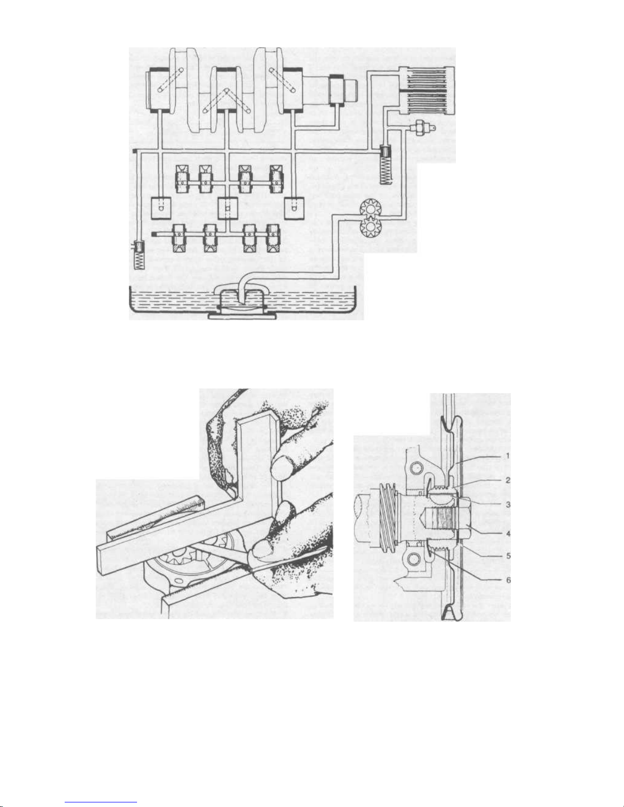
FIG.1.3 LUBRICATION SYSTEM - DIAGRAMMATIC
DRAWING
FIG.1.4 MEASURING OIL PUMP GEAR END CLEARANCE
(Sec 10)
FIG.1.5 CRANKSHAFT PULLEY
WHEEL - CROSS SECTION
(Sec 9)
1 Pulley
2 Oil return scroll
3 Woodruff key
4 Securing bolt
5 Lock washer
6 Oil thrower disc
Downloaded from www.Manualslib.com manuals search engine

24
Chapter 1/Engine
if you are going to do so anyway it will be simpler to take the
connecting rods off the crankshaft afterwards. Start with No. 1
and, using a socket with an extension, slacken the two connect-
ing rod cap nuts by inserting the extension into the crankcase: It
is important to have the crankshaft positioned so that the socket
spanner fits squarely and completely onto the head of each nut.
2 Once both are loose, carefully undo each one and keep them
captive in the socket when undoing them so as not to drop them
in the crankcase. The cap will be left behind and may be
awkward to retrieve. Tip the engine to shake it out if necessary.
Retrieve both halves of the bearing shells also. Loosely refit the
cap to the connecting rod noting the two matching numbers on
the shoulders of the rod and cap which must line up on
replacement. It is a good idea to note on a piece of paper which
serial number applies to which cylinder number. This avoids the
need to mark the connecting rods further. If the same rods and
pistons are being put back it is very desirable that they should go
back in the same position as they came out.
3 It is unlikely that a connecting rod will be bent except in
cases of severe piston damage and seizure. It is not normally
within the scope of the owner to check the alignment of a
connecting rod with the necessary accuracy so if in doubt have it
checked by someone with the proper facilities. It is in order to
have slightly bent connecting rods straightened - the manufacturers provide special jigs for the purpose. If a rod needs
replacement, care should be taken to ensure that it is within 10
grams in weight of the others. If too heavy, connecting rods may
be lightened by removing metal from the shoulders near the big
end of the wiper parts where the bearing cap mates up to it.
4 The small end bushes are also subject to wear. At a temperature of 70°F the piston (gudgeon) pin should be a push fit. No
axial or rocking movement should be apparent. The fitting of
new bushes is a specialist task and although the bushes
themselves may be easily pressed in it is necessary to ream them
to fit the gudgeon pins. Unless you have reamers readily avail-
able and the knowledge of how to use them this should be
done by a firm (or individual) specialising in engine reconditioning. Remember that if you are fitting new pistons it may
be necessary to fit new connecting rod bushes. If you are lucky
the new gudgeon pins may fit the old bushes properly however.
Make sure that the new bushes have been drilled to match the oil
holes in the connecting rod This should be done before reaming
so that there are no burrs on the bush bore.
5 The shell bearings from the big end are matt grey in colour
when in good condition. If the engine has done a considerable
mileage it is good policy to renew them anyway when the
opportunity presents itself. To make sure you get the correct
replacement size make a note of the numbers on the back of the
bearing shell or take it along to the supplier.
6 If the crankshaft is being reground new bearing shells will be
required anyway and these are normally available from the firm
which does the regrinding and will be matched to the degree of
regrjnding carried out .
15 Camshaft and tappets - removal and renovation
1 The camshaft and tappets can be removed only after splitting
the crankcase and this procedure is described in the section on
crankshaft removal.
2 Having split the crankcase the tappets should be checked in
their respective bores in the crankcase and no excessive side-play
should be apparent. The faces of the tappets which bear against
the camshaft lobes should also have a clear, smooth shiny
surface. If they show signs of pitting or serious wear they should
be renewed. Refacing is possible with proper grinding facilities
but the economics of this need investigating first. The lobes of
the camshaft should be examined for any indications of flat
spots, pitting or extreme wear on the bearing surfaces. Minor
blemishes may be smoothed down with a 120 grain oil stone and
polished with one of 300 grain. The bearing journals also should
be checked in the same way as those on the crankshaft. The
camshaft bearings are renewable.
3 The gear wheel which is riveted to the end of the camshaft
must be perfectly tight and the teeth should be examined for
any signs of breakage or excessive wear. It may be possible to
have a new gear wheel fitted to the existing camshaft - much
depends on the facilities available in your area. It is not a job to
be attempted by the owner.
16 Flywheel - removal and renovation
1 With the engine removed from the car the flywheel may be
removed after the clutch cover has been taken off (as described
in Chapter 5. See Fig. 1.8.
2 The flywheel is held by a single centre bolt which is tightened
up to 253 ft/lbs so do not think you can get it undone just like
that. It was necessary to obtain a piece of angle iron to lock the
flywheel by putting the angle iron across two of the clutch bolts
which were put back into the flywheel. If by yourself the other
end of the angle iron (or flat bar will do) can then be held in the
vice with the engine on the bench.
3 A 36 mm socket is then put on the bolt with the longest
handle from the socket set (do not under any circumstances try
to use anything other than a correct sized socket - you could
easily cause serious damage or even hurt yourself). A piece of
steel pipe is then put over the socket handle and leaned on with
considerable weight. The bolt slackens with no fuss at all. It may
cost you a little money to get the stuff to do this job properly
but we cannot recommend any other way.
4 Remove the bolt and large washer and before going any
further make an identifiable mark on the flywheel hub so that
you can re-locate the flywheel in the same place. The matching
mark on the crankshaft cannot be made until the flywheel is off,
so remember not to move the flywheel when it has come off
until you can make a corresponding line up mark on the crank-
shaft flange. This is important as there may be no other way of
knowing the correct position of balance.
5 The flywheel is now located only by four dowel pegs which
fit into holes in the crankshaft flange and flywheel boss. Put a
piece of wood under the edge of the flywheel starter teeth to
support the weight and then use a soft mallet or block of wood
to tap the edges of the flywheel and draw it off. Do not try and
lever it off with anything against the crankcase or you are likely
to crack the casting and that will be expensive.
6 When the flywheel is free, hold it steady, and remove the
metal or paper gasket fitted over the four dowel pegs in the
flange. Then make the second line-up mark on the crankshaft
referred to in paragraph 4.
7 The dowel pegs are a precision fit into both the flange and
flywheel. If any of these should be a slack fit there is considerable risk of the flywheel working loose, despite the tightness of
the securing bolt. Where a flywheel has worked loose and caused
the holes to become oval a new flywheel will be needed. (The
precision work of boring and fitting oversize dowel pegs would
cost more).
8 Another area of wear is in the starter teeth. These are
machined into the flywheel itself so there is no question of
fitting a new ring gear. If the teeth have become seriously
chewed up it is in order to have up to 2 mm (0.08 inch)
machined off on the clutch side of the teeth. The teeth should
then be chamfered and de-burred. Any good machine shop
should be able to carry out this work.
9 Examine also the land on the flywheel boss where the oil seal
runs. If this is severely ridged it may need cleaning up on a lathe
also. Any such ridging is very exceptional.
17 Crankshaft oil seal - removal
1 The crankshaft oil seal may be removed after taking the
engine from the car and removing the flywheel.
2 The oil seal may be levered out of the crankcase with a
screwdriver or similar but great care must be taken to avoid
damaging the crankcase where the seal seats. This means that the
Downloaded from www.Manualslib.com manuals search engine
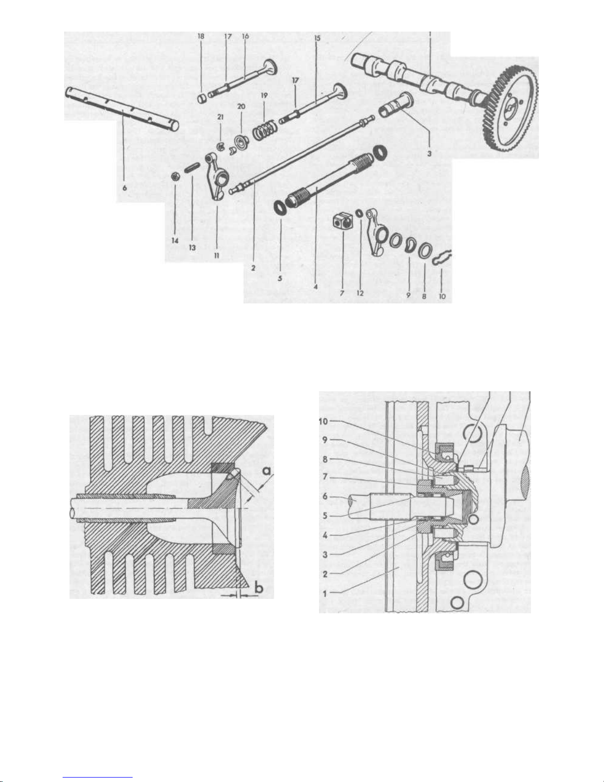
FIG.1.6 CAMSHAFT AND VALVES- EXPLODED VIEW (Sec 15)
1 Camshaft and gear
assembly
2 Pushrod
3 Tappet
4 Pushrod tube
5 Pushrod tube seal
6 Rocker shaft
7 Shaft support bracket
8 Thrust washer
9 Corrugated washer
10 Securing clip
11 Rocker arm
12 Sealing ring
13 Tappet adjusting
screw
14 Locknut
15 Inlet valve
16 Exhaust valve
17 Oil wiper
18 Valve cap
19 Valve spring
20 Valve spring seat
21 Valve cotter halves
11 12 13
FIG.1.7 VALVES - CROSS SECTION OF SEAT (Sec 12)
a - seat width 1.7 - 2 mm exhaust and 1.25 - 1.65 mm inlet
b- 1 mm Minimum, all valves
FIG.1.8 CROSS SECTION VIEW OF THE FLYWHEEL END OF
THE CRANKSHAFT (Sec 16)
/ Flywheel
2 Gland nut
3 Needle bearing
4 Felt ring
5 Retaining ring
6 Gearbox input shaft
7 Lock washer
8 Dowel peg
9 'O' ring
10 Crankshaft oil
seal
11 Shims
12 Rear main bearing
13 Crankshaft
25
Downloaded from www.Manualslib.com manuals search engine

26
Chapter 1 /Engine
point of the tool used must not be allowed to dig into the
crankcase.
3 When the oil seal is removed a number of shims which fit
between the flywheel hub and the flange on the front main
bearing will be observed. There should be three of them normal-
ly. These govern the amount of crankshaft endfloat. Make sure
they are kept safely and not damaged.
4 If the crankcase is being split anyway it is simpler to wait
until this is done when the oil seal may be easily lifted out.
18 Crankshaft and main bearings - removal and renovation
1 In order to remove the crankshaft, camshaft and cam
followers (tappets) the two halves of the crankcase will need to
be separated. Unless you are quite sure that this is essential do
not do it. It is not worth opening the crankcase up just to 'have a
look'. Remember also that the main bearing shells are much
more expensive than on conventional cars (three of the four are
not split) and before you can remove one of them two gears
must be removed from the crankshaft. These gears are on very
tight and are difficult to draw off.
2 Having decided to split the crankcase, remove the generator
pedestal and prop the crankcase on its left side. All pistons and
cylinders should already have been removed as should the
flywheel. If the flywheel is left on it will add to the difficulty of
controlling the weight of the crankshaft when the two halves
release it. It will also be much more difficult to remove from the
crankshaft afterwards. The connecting rods may be left on as
these will be easier to remove after the crankcase is split.
3 The two halves are held together by large and small studs and
nuts and two bolts and nuts. Slacken all the smaller nuts
followed by the large nuts. Before starting to separate the two
halves remember that the crankshaft and camshaft are held
between them and you do not want either to fall out haphazard-
ly. So if you keep the crankcase tilted to the left they will both
rest in that half.
4 Separate the two halves by tapping lightly at the projecting
lugs on the left half with a soft faced mallet or piece of wood.
Do not hit anything hard. This progressive gentle tapping at the
four corners will gradually increase the gap between the two
until the right hand half will be free enough to lift off the studs.
If you have a second pair of hands to help so much the better.
When the right hand half has moved out a little way there will
probably be a light clatter as one or more of the four cam
followers in the right hand half fall out. If possible try and get
hold of these and arrange them somewhere (in an egg box or
numbered row on a shelf) so that they may be put back in the
same bores.
5 Put the crankcase half in a safe place where it cannot fall or
be damaged.
6 Lift out the camshaft from the other half of the crankcase.
The bearing shells may be left in position. If they fall out note
where they came from. If being renewed anyway take them out.
One half of one shell is flanged to take the camshaft end thrust
and the crankcase is suitably machined to accept it.
7 The tappets from the left hand half of the crankcase may
now be taken out. Keep them in order like the others so they
may be replaced in the same bores.
8 The crankshaft can now be lifted out and should be carefully
put somewhere safe. The bearing shell halves for No. 2 main
bearing should be removed from their locations in each half of
the crankcase. Note that the location of each main bearing is by
a dowel peg which locates each bearing shell. These normally
remain in the crankcase but if any have come out with the
bearings retrieve them now before they get lost.
9 It is possible to examine the connecting rod big end journals
after removing the pistons and connecting rods without splitting
the crankcase, but only visually. They cannot be measured satisfactorily. Provided there is no good reason to suspect that the
big end bearings were seriously worn and that the surface of the
journals are bright and smooth with no signs of pitting or scoring
then there should be no need to proceed further.
10 The main crankshaft bearing journals may be examined only
when the crankcase has been split and the crankshaft taken out.
An indication of serious wear in these bearings can be obtained
by checking the crankshaft for signs of slackness in the bearings
before the crankcase is split. A wooden lever put through one of
the cylinder apertures can be used to test for any indications of
rocking in the bearings. If there is any then the bearing shells will
almost certainly need renewal, even though the crankshaft
journals themselves may be serviceable. The journals should be
perfectly smooth with a bright mirror finish. They should be
measured with a micrometer across the diameter for signs of
ovality. If any measurement should differ by more than 0.03
mm (0.0011 inch) from any other the crankshaft should be re-
ground. This means taking it to a specialist engineering firm who
can grind it to the undersizes permissible and supply the match-
ing new bearing shells. In view of the need to remove the two
gears in order to examine No. 3 main bearing journal the
condition of the gears should also be checked, in conjunction
with their respective mating gears on the camshaft and distri-
butor drive spindle. The bronze worm gear which drives the
distributor drive spindle is the most likely to show signs of wear.
Any noticeable ridging or 'feathering' and variations in thickness
of each spiral tooth indicate wear and renewal is probably justifi-
able.
11 Three of the four main bearings may be removed as soon as
the crankshaft is taken from the crankcase. No. 1 is a circular
flanged shell which is drawn off the flywheel end, No. 2 is the
split bearing and No. 4 is a narrow circular bearing which can be
drawn off the crankshaft pulley end. No. 3 however, is trapped
by the helical gear which drives the camshaft. In front of this
gear is a spacer and the distributor drive shaft worm gear, an oil
thrower disc and Woodruff key.
12 To remove No. 3 main bearing first tap the Woodruff key out
of the shaft and keep it safe. Take off the oil thrower disc. The
two gears are a tight keyed fit onto the shaft and the only way
to get them off is by using a proper sprocket puller which has
grips which will fit snugly and completely behind the helical gear
so that both the gears and the spacer can be drawn off together.
If you have difficulty in fitting the puller in the small gap
between the bearing and gear do not try and pull off the gear
gripping only against the gear teeth. You will either chip them or
break them off. If you are committed to new bearings anyhow,
cut the old bearing off to enable you to get the puller properly
seated behind the gear.
13 If, when you start putting the pressure on it is obvious that
considerable force is going to be needed it is best to clamp the
legs of the puller to prevent them spreading and possibly flying
off and causing damage to the gear. Some pullers have a clamp
incorporated for such a purpose. If you have press facilities
available so much the better but on no account should you try
to hammer the gears off. It is virtually impossible to do this
without damaging the gears.
14 With the two gears removed the bearing can be taken off the
shaft.
15 Having taken off the No. 3 bearing it would be unwise not to
renew the complete set as a matter of course. If the crankshaft
needs re-grinding then the new bearings will need to be of the
correct undersize to suit the amount removed during re-grinding.
Such bearings will normally be supplied by the firm doing the
re-grinding work. If the crankshaft is not being re-ground make
sure that the bearings obtained are exactly the same dimensions
as those removed. This can be verified by checking the numbers
on the bearings which normally include an indication of whether
they are standard or undersize. Do not forget that it is always
possible that the crankshaft may have been re-ground before.
19 Distributor drive shaft - removal
1 The procedure for removing and replacing the distributor
drive shaft from an assembled engine is given in Chapter 4. It is
mentioned here because it is in order to leave it in position right
up until the time when the crankshaft is divided. It should,
however, be removed before the crankcase is reassembled.
Downloaded from www.Manualslib.com manuals search engine
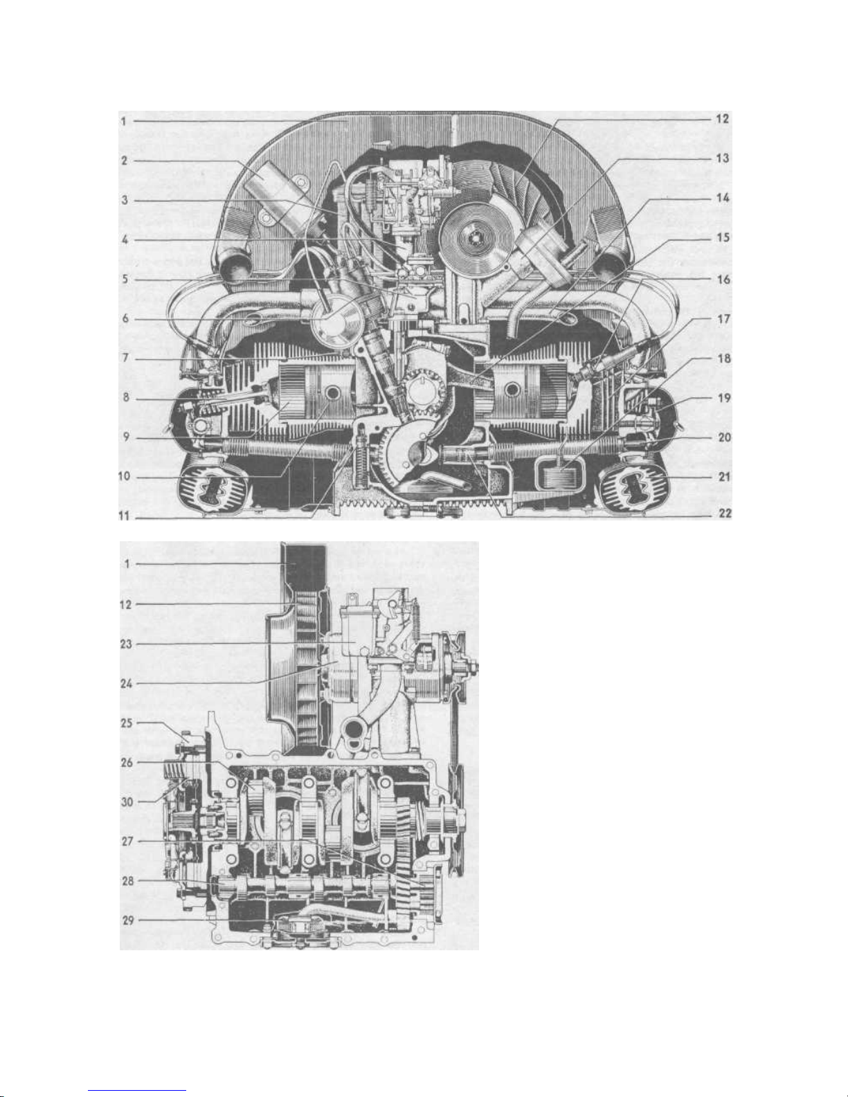
27
FIG.1.9 ENGINE - CROSS SECTION VIEWS
1 Fan housing
2 Coil
3 Oil cover
4 Inlet manifold
5 Fuel pump
6 Distributor
7 Oil pressure switch
8 Valve
9 Cylinder
10 Piston
11 Oil pressure relief valve
12 Fan
13 Oil filler
14 Intake manifold preheater pipe
15 Connecting rod
16 Spark plug
17 Cylinder head
18 Thermostat
19 Rotor arm
20 Push rod
21 Heat exchange
22 Cam follower (tappet)
23 Carburettor
24 Dynamo
25 Flywheel
26 Crankshaft
27 Oil pump
28 Camshaft
29 Oil strainer
30 Clutch
NOTE: This drawing does not show all the later
modifications (e.g. 3 section inlet manifold, one
piece fuel pump) but the basic format is the same.
Downloaded from www.Manualslib.com manuals search engine

28
Chapter 1 /Engine
20 Crankcase - examination and renovation
The crankcase should be free from cracks or any other form
of damage and the two mating edges must be quite free from
dents, scratches and burrs which could in any way affect their
precise alignment when both are clamped together. The crankshaft bearing locations should also be examined for any signs of
damage or distortion. In an engine which has been permitted to
run on with worn out main bearings it is possible that the
bearing shells themselves will have been 'hammered' by the
vibration of the crankshaft into the crankcase. This will mean
that new bearings will not be a tight fit in their crankcase
locations. In such instances the crankcase must be scrapped. In
these circumstances the best action would be to abandon ideas
of renovating the engine and obtain a complete replacement.
Make sure that the camshaft bearing surfaces are in good
condition.
The studs in the crankcase, both for attaching the cylinder
heads and for the two halves, must be tight in their threads. Any
sign of looseness which may be due to worn threads in the alloy
crankcase is reparable. It will mean drilling and fitting a 'Helicoil'
insert - which is a new thread in effect. This can be done at the
Volkswagen agents for certain and at many other places where
aluminium engines and castings are often being repaired. In any
case check the economics before buying a lot of other parts.
21 Engine reassembly - general
1 As mentioned earlier, the Volkswagen engine is more
complex in assembly than a conventional engine with a single
cylinder block. It is therefore essential to get everything right
first time and this means DO NOT RUSH IT. More than likely
you will not have assembled an engine like this before so the
order of assembly on other types cannot be relied upon for
experience.
2 Before starting work clear the bench and arrange all the
components nearby. The assembly surface must be particularly
clean and it is a good idea to cover the working surface with
sheets of strong paper. Have all the necessary gaskets and seals
available together with clean oil in a can or convenient dispenser
pack. If you are replacing bearing shells, cam followers and
various other parts make sure the old parts are kept away from
the assembly area in a carton or something. It is very easy to
pick up an old cam follower for instance by mistake. At each
stage, get the relevant batch of nuts and bolts ready - having
cleaned the grit from them in a paraffin bath. A plentiful supply
of clean cloths is the final requirement. Do not forget to clean
the tools you will use as well. It is easy to transfer grit from a
spanner to the engine with your hands and any small pieces of
grit can ruin many hours and pounds worth of work. Again
finally, take your time!
22 Crankshaft - assembly of gears and main bearings
1 With the crankshaft thoroughly clean and the oilways blown
out lubricate No. 3 journal with clean engine oil (photos). No. 3
main bearing is one of the two largest one-piece circular shells. It
does not have a flange on it. This bearing goes on to the journal
one way only - that is with the small dowel peg hole (which is
not central) towards the flywheel end of the crankshaft (photo).
Do not get this wrong or assembly will grind to a halt when you
try to locate the bearing in the crankcase halves.
2 Next replace the camshaft drive gear. Before putting it on
examine the surfaces of the crankshaft and key and the bore of
the gear. If there are signs of slight scoring as a result of seizure
when the gear was drawn off, clean them up with a very fine file.
This will avoid a tendency to bind on replacement. The gear
keyway should be lined up with the key in the shaft and the
chamfered edge of the gear bore must face the flywheel end - i.e.
it goes on first (photo). The gear may be difficult to start on the
shaft so keep it square and make sure that the keyway is
precisely lined up (photo). This is most important because if
wrong you will have to draw the gear off and start again. It can
then be drifted on with firm evenly spaced strikes, around the
gear (away from the teeth). Keep it square, particularly at the
start, and drive it fully home. The crankshaft should be clamped
between padded vice jaws for this operation.
3 Next the spacer ring followed by the spiral distributor drive
gear are fitted. They can go on either way round and the gear
should be carefully drifted up to the spacer without damaging
the spiral teeth (photos). Finally, fit the retaining circlip and
make sure it fits snugly in its groove (photo). If it will not go in
the groove then one of the gears has not been fully driven onto
the crankshaft and this must be rectified.
4 Next fit the small circular bearing over the end journal, once
again making sure that the offset dowel peg hole is towards the
flywheel end of the crankshaft (photo). Do not confuse the
dowel peg hole with the circular groove machined in the outside
of this bearing. Lubricate the journal.
5 Next fit the oil thrower disc with the concave face outwards
(photo). Fit the Woodruff key (for the crankshaft pulley wheel)
into the keyway now as this will prevent the disc from falling off
inadvertently, (photo).
23 Connecting rods - assembly to crankshaft
1 If the crankcase has been split the connecting rods (without
the pistons) should first be fitted to the crankshaft. Check that
the gudgeon pins fit correctly in their respective small end
bushes, otherwise difficulty will be encountered in fitting the
pistons later. If you are refitting the connecting rods to the
crankshaft in the assembled crankcase, note the additional
information at the end of this section.
2 Lay the crankshaft down on the bench with the flywheel
flange end away from you.
3 Arrange the connecting rods, two on each side of the crankshaft with Nos. 1 and 2 on the right, No. 1 nearest the flywheel
end and No. 3 and 4 on the left with No. 3 nearest the flywheel
end. Align the numbers on the connecting rod and cap (photo).
Note that there is a forge mark (photo) on the connecting rod
which often appears on the side opposite to the numbers. This
forge mark must always be uppermost when installing the
connecting rod. The first crank on the crankshaft, from the
flywheel end, is No. 3, left. Pick up the connecting rod and
after wiping the bearing surface perfectly clean, fit the bearing
shell with the notch engaging in the corresponding notch in
the rod. Fit the other half of the shell bearing to the cap in
the same fashion (photo). Next, liberally oil the bearing journal
with clean oil and assemble the rod to the crankshaft (photo).
Match the two numbers on the shoulders and with the rod
pointing to the left face them downwards. Replace the cap
and nuts finger tight so that the assembly is not loose on the
crankshaft (photo).
4 Repeat this for No. 1, right, which is the second crank from
the flywheel end followed by No. 4, left and No. 2, right. It is
easy to get confused while doing this. If your crankshaft
assembly does not look like the one in Fig. 1.10 rotate the
crankshaft 180° but keep the connecting rods pointing the same
way. Then it should look familiar! Above all, think and do not
rush.
5 Once the rods are correctly fitted to the crankshaft the bolts
will need tightening to the correct torque of 3.3 mkg (24 ft lbs).
The best way to do this is to mount the crankshaft vertically in
the vice, clamping the No. 4 bearing journal firmly between two
pieces of wood (photo). All the connecting rod bolts can then be
tightened. It is advisable to tap the shoulders of each rod with a
hammer to relieve any pre-tention which can be set up between
the mating surfaces of the cap and the rod. When the cap bolts
are fully tightened the connecting rods should be able to rotate
around the journals under their own weight. There should be no
tight or 'free' spots anywhere although if you are fitting new
Downloaded from www.Manualslib.com manuals search engine
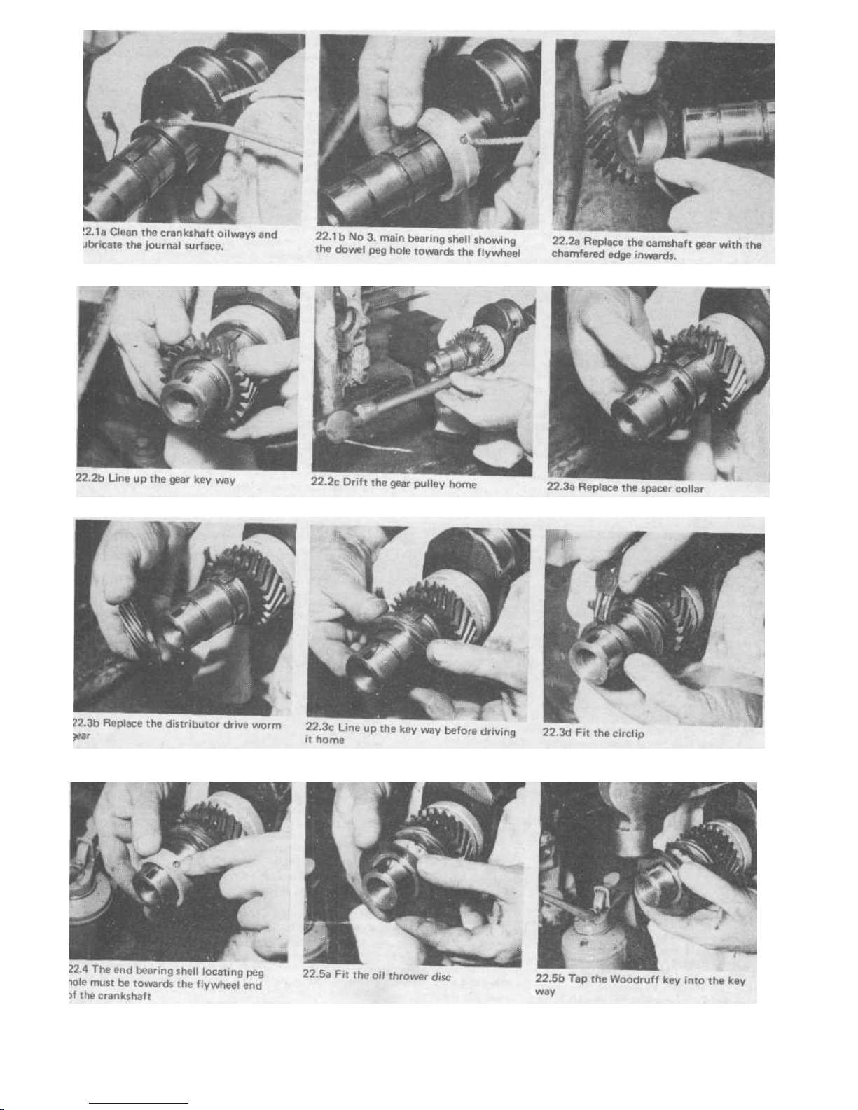
Downloaded from www.Manualslib.com manuals search engine

30
Chapter 1 /Engine
shells to an un-reground crankshaft this is possible. If very
noticeable however, it indicates that the journal is out of round.
If rods on a reground crankshaft are slightly tight the engine will
need running-in. If very tight then the regrinding tolerances are
wrong and it should be returned to the machinists for correction.
6 Place the assembled crankshaft on the bench once more, as
before, with each connecting rod facing its proper cylinder
position.
7 If you are fitting the connecting rod to an assembled crankcase/crankshaft lay out the rods alongside their respective
cylinder positions as already explained and fit the shells into the
rods and caps. Turn the crankshaft so that the journal for the
rod to be fitted is nearest its crankcase opening. The cap must
then be placed on the journal and the rod fitted to it. This is
easy if you have four hands and fingers ten inches long! It is
helpful to have a piece of bent metal rod which can be put
through from the opposite side of the crankcase to hold the cap
on the journal whilst the rod and nuts are being fitted. A certain
amount of patience is essential as it is more than likely that you
will drop a bolt or bearing cap into the crankcase at some stage
and have to shake it out. Do not use grease to hold parts
together for this assembly. It will probably affect lubrication
seriously. The most important thing to ensure is that a bearing
shell does not drop out unnoticed and get trapped and damaged
while you are fiddling about. So if a shell drops in the crankcase
go easy on rotating the crankshaft until you get it out. As soon
as the first connecting rod is fitted tighten the bolts to the
correct torque and check that it moves freely but without any
clearance. You will be refitting new shells to the original journal
sizes so if something seems amiss - bearing too tight or too loose
- make sure you have bought the correct shells by comparing the
numbers and oversize (if any) with the old ones removed.
24 Crankcase, crankshaft, camshaft and cam followers - reassembly
1 The items in this section heading are grouped together for the
^«*< lj3O<i rare*?. tf\a\ \<iw^ %\\ Vv&Me \o toe a^semfoSeo. togetYier.
None may be omitted. (See Fig. 1.10).
2 Both crankcase halves must be perfectly clean, inside and
out. All traces of jointing compound must be removed from the
mating faces, the roots of the studs, and the chamfers in the stud
hole mating faces. Use a solvent such as carbon tetrachloride to
remove sealing compound and not a scraper which could damage
the aluminium surfaces. The distributor drive gear should have
been removed. The oil pump suction pipe must be tightly fitted.
If loose it must be peened in position.
3 Place the left hand half of the crankcase on the bench with
the flywheel end away from you and leaning over so that it rests
on the cylinder head studs.
4 Oil the four cam followers for the left half and place them in
their bores. If new followers are being fitted, it is possible that
their heads may be slightly thicker than the originals, so compare
them (photo). If they are thicker then it is essential to check the
clearance between them and the crankcase with the cam lift at
its highest point. So having placed the cam followers in position
replace the camshaft temporarily, with its shell bearings and
revolve it (photos). If any of the cam lobes should jam the
followers against the crankcase then clearance will have to be
provided by relieving the crankcase by about 1—2 mm behind
each cam follower head. This can be done by a small, end face,
grindstone in a power drill by a competent handyman. Great
precision is not important provided that there is no damage to
the actual cam follower bore and the resulting clearance is
adequate to permit full unobstructed movement of the cam and
follower. Be sure to remove all traces of metal after such work.
Repeat this check for the four cam followers in the right hand
half of the crankcase.
5 Fit the flanged No. 1 bearing shell at the flywheel end of the
crankshaft. Once again make sure that the off-centre locating
dowel peg hole goes towards the flywheel end (photo). Look to
see that the corresponding dowel pegs in the crankcase will mate
up. The bearing surface of the journal should be well lubricated
with clean oil but keep the outside surfaces of the bearing shell
clean and dry.
6 Place one half of the split shell in position at No. 2 bearing in
the crankcase, engaging the dowel pin in the hole (photo).
Lubricate the bearing with clean oil.
7 The crankshaft assembly should now be placed into position
in the left hand crankcase half (photo). The three dowel holes in
the circular bearings will need lining up so that they will locate
snugly and Nos. 3 and 4 connecting rods must pass through their
respective apertures. It is a good idea to lift the assembly up by
Nos. 1 and 2 connecting rods for this operation. Do not force
anything into place. The circular bearings may need rotating a
little until you can feel the pegs engage. Ensure the thrower disc
locates within the oil thrower recess in the casting. Once all the
bearing pegs are located a little pressure will ensure that the
assembly and bearings are completely seated. If it is stubborn for
any reason lift it out, pause, look, think and have another go.
8 Next fit the camshaft bearing shells into clean locations,
engaging the notches in the crankcase (photo). Then oil the
bearings in readiness for the camshaft.
9 Turn the crankshaft carefully until two teeth, each marked
with a dimple are visible and well clear of the edge of the crankcase. There is a single tooth on the camshaft gear similarly
marked which must mesh between them (photo). Engage the
teeth and roll the camshaft round, in mesh still, into its bearing
location. Then turn the gears again to check that the timing
marks are still correctly aligned.
10 Now fit the four tappets (cam followers) into the right hand
half of the crankcase and if it seems as though they might fall
out when it is lifted and tilted then put a dab of grease behind
the lip of each one to help stick it in position.
11 Fit the other half of No. 2 bearing shell into the right half of
the crankshaft locating it over its dowel peg correctly.
12 Now thinly coat the two clean, smooth mating surfaces of
the crankcase halves with aluminium alloy jointing compound
(photo). Use a good quality product such as Volkswagen them-
selves recommend or 'Hytomac'. Neither is cheap feu* \<rei\ S/OM
do not want your crankcase to leak oil when it gets hot. Make
%\»« XV* v*«> wrtmsa are coaieei comp'iet^-y toux thinly anO
evenly. Take care to cover round the base of the studs. Do not
let any compound get into oilways or other places where it is not
wanted and may cause obstruction or binding.
13 The six larger studs may have rubber sealing rings at the roots
and these should all be renewed if fitted.
14 Place the right hand half of the crankcase over the studs of
the left and carefully slide it down until it just touches the
crankshaft bearings (photo).
15 Coat the circular camshaft sealing plug with jointing com-
pound and place it in position in its groove in the left hand half
at the flywheel end of the camshaft, with the recess facing
inwards.
16 Move the two halves together, tapping lightly with a block of
wood if necessary. Use no force - none should be necessary.
17 Now stop and check:
1 Are all the connecting rods protruding from their proper
holes? Cap nuts tight?
2 Are all four bearings, two gears and oil thrower disc fitted to
the crankshaft?
3 Are all eight cam followers in position?
4 You did not forget the camshaft? (It has been known). Did
you mesh the timing properly?
5 Camshaft sealer plug?
All in order, replace all the nuts on the studs finger tight.
Revolve the crankshaft just to make sure that everything moves
freely at this stage at least.
18 It is important to tighten down the stud nuts evenly and in
the correct order. Tighten first the six large nuts to a torque of
1.5 mkg (11 ft lbs) only, followed by all the smaller nuts to the
same torques. Then tighten the small nut near the lower large
stud clamping round No. 1 main bearing to its full torque of 2
mkg (14 ft lbs).
Downloaded from www.Manualslib.com manuals search engine
 Loading...