


 Loading...
VIZIO VP504 FHDTV10A User Manual
Dear VIZIO Customer,
Congratulations on your new VIZIO VP504 FHDTV10A High Definition PLASMA Television purchase. Thank you for your support. For maximum benefit of your set, please read these instructions before making any adjustments, and retain them for future reference. We hope you will experience many years of enjoyment from your new VIZIO VP504 FHDTV10A High Definition Television.
For assistance, please call (877)-698-4946 or e- mail us at techsupport@vizio.com.
To purchase or inquire about accessories and installation services for your VIZIO PLASMA HDTV, please visit our website at www.vizio.com or call toll free at (888)-849-4623.
We recommend you register your VIZIO VP504 FHDTV10A either at our website www.VIZIO.com or fill in your registration card and mail it in. For peace of mind and to protect your investment beyond the standard warranty, VIZIO offers on-site extended warranty service plans. These plans give additional coverage during the standard warranty period. Visit our website or call us to purchase a plan.
Write down the serial number located on the back of your VP504 FHDTV10A.
__ __ __ __ __ __ __ __ __ __ __ __ __ __
Purchase Date _____________________
VIZIO is a registered trademark of VIZIO, Inc. dba V, Inc. HDMI logo and “High Definition Multimedia Interface” are registered trademarks of HDMI Licensing LLC.
Manufactured under license from Dolby Laboratories.
Dolby and the double-D symbol are trademarks of Dolby Laboratories.
Version 7/2/2008 |
1 |
|
www.VIZIO.com |
VIZIO VP504 FHDTV10A User Manual
Important Safety Instructions
This product is designed and manufactured to operate within defined design limits, and misuse may result in electric shock or fire. To prevent the product from being damaged, the following rules should be observed for the installation, use and maintenance of the product. Read the following safety instructions before operating the display. Keep these instructions in a safe place for future reference.
•To reduce the risk of electric shock or component damage, switch off the power before connecting other components to the VP504 FHDTV10A.
•Unplug the power cord before cleaning the VP504 FHDTV10A LCD. A damp cloth is sufficient for cleaning the VP504 FHDTV10A. Do not use a liquid or a spray cleaner for cleaning the product. Do not use abrasive cleaners.
•Always use the accessories recommended by the manufacturer to insure compatibility.
•When moving the VP504 FHDTV10A from an area of low temperature to an area of high temperature, condensation may form on the housing. Do not turn on the VP504 FHDTV10A immediately after this to avoid causing fire, electric shock or component damage.
•Do not place the VP504 FHDTV10A on an unstable cart, stand, or table. If the VP504 FHDTV10A falls, it can injure a person and cause serious damage to the appliance. Use only a cart or stand recommended by the manufacturer or sold with the VP504 FHDTV10A.
•A distance of at least 3 feet should be maintained between the VP504 FHDTV10A and any heat source, i.e. radiator, heater, oven, amplifier etc. Do not install the product close to smoke. Operating the product close to smoke or moisture may cause fire or electric shock.
•Slots and openings in the back and bottom of the cabinet are provided for ventilation. To ensure reliable operation of the VP504 FHDTV10A and to protect it from overheating, be sure these openings are not blocked or covered. Do not place the VP504 FHDTV10A in a bookcase or cabinet unless proper ventilation is provided.
•Never push any object into the slot on the VP504 FHDTV10A cabinet. Do not place any objects on the top of the product. It could short circuit parts causing a fire or electric shock. Never spill liquids on the VP504 FHDTV10A.
•The VP504 FHDTV10A should be operated only from the type of power source indicated on the label. If you are not sure of the type of power supplied to your home, consult your dealer or local power company.
•The power cable must be replaced when using different voltage from that specified in the User Manual. For more information, contact your dealer.
•The VP504 FHDTV10A is equipped with a three-pronged grounded plug, a plug with a third (grounding) pin. This plug will fit only into a grounded power outlet as a safety feature. If your outlet does not accommodate the three-wire
plug, have an electrician install the correct outlet, or use an adapter to ground the appliance safely.
Do not defeat the safety purpose of the grounded plug.
•Appliance inlet (or AC inlet) is used as the disconnect device.
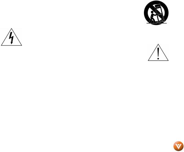
•Use only with the cart, stand, tripod, bracket or table specified by manufacturer, or sold with the apparatus. When a cart is used, use caution when moving the cart/apparatus combination to avoid injury from tip-over.
•The lightning flash with arrowhead symbol , within an equilateral triangle, is intended to alert the user to the presence of not isolated dangerous voltage within the inside of the product that may be sufficient magnitude to constitute a risk of electric shock to persons.
• The exclamation point within an equilateral triangle is intended to alert the user to the presence of important operating and servicing instructions in the literature
accompanying the appliance.
•Do not overload power strips and extension cords. Overloading can result in fire or electric shock.
•The wall socket shall be installed near the equipment and shall be easily accessible.
•Only the marked power source can be used for the product. Any power source other than the specified one may cause fire or electric shock.
•Do not touch the power cord during lightning. To avoid electric shock, avoid handling the power cord during electrical storms.
•Unplug the unit during a lightening storm or when it will not be used for long period of time. This will protect the VP504 FHDTV10A from damage due to power surges.
•Do not attempt to repair or service the product yourself. Opening or removing the back cover may expose you to high voltages, the risk of electric shock, and other hazards. If repair is required, please contact your dealer and refer all servicing to qualified service personnel.
•Keep the product away from moisture. Do not expose this appliance to rain or moisture. If water penetrates into the product, unplug the power cord and contact your dealer. Continuous use in this case may result in fire or electric shock.
•Do not use the product if any abnormality occurs. If any smoke or odor becomes apparent, unplug the power cord and contact your dealer immediately. Do not try to repair the product yourself.
•Avoid using dropped or damaged appliances. If the product is dropped and the housing is damaged, the internal components may function abnormally. Unplug the power cord immediately and contact your dealer for repair. Continued use of the product may cause fire or electric shock.
•Do not install the product in an area with heavy dust or high humidity. Operating the product in environments with heavy dust or high humidity may cause fire or electric shock.
•Follow instructions for moving the product. Ensure that the power connector and any other cables are unplugged before moving the product.
•Hold the power connector when removing the power cable. Pulling the power cable itself may damage the wires inside the cable and cause fire or electric shock. When the product will not be used for an extended period of time, unplug the power connector.
•To reduce risk of electric shock, do not touch the connector with wet hands.
Version 7/2/2008 |
2 |
|
www.VIZIO.com |
VIZIO VP504 FHDTV10A User Manual
•Insert batteries in accordance with instructions. Incorrect polarities may cause damage and leakage of the batteries, operator injury and contamination the remote controller.
•If any of the following occurs please contact the dealer:
o The power connector fails or frays.
o Liquid sprays or any object drops into the VP504 FHDTV10A. o The Display is exposed to rain or other moisture.
o The Display is dropped or damaged in any way.
oThe performance of the Display changes substantially.
•Operating environment. Temperature: 40˚F ~ 95˚F, Humidity: 20% ~ 80% non-condensing, Altitude: 0 ~ 6500ft (0 ~ 2000m)
Television Antenna Connection Protection
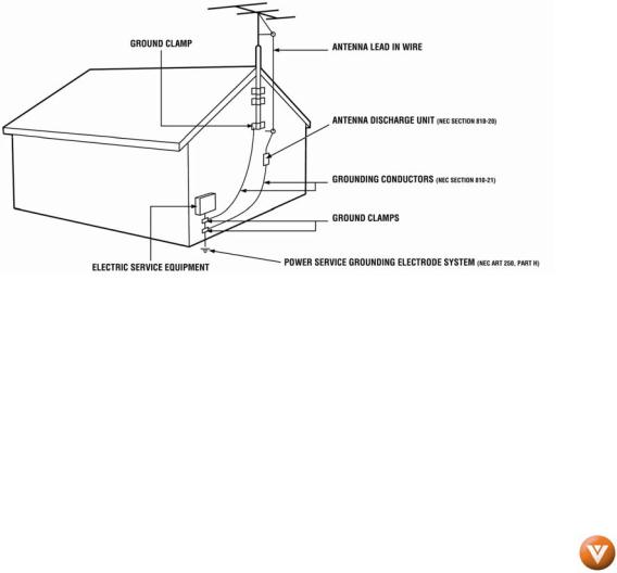
External Television Antenna Grounding
If an outside antenna/satellite dish or cable system is to be connected to the TV, make sure that the antenna or cable system is electrically grounded to provide some protection against voltage surges and static charges.
Article 810 of the National Electrical Code, ANSI/NFPSA 70, provides information with regard to proper grounding of the mast and supporting structure, grounding of the lead-in wire to an antenna discharge unit, size of the grounding conductors, location of antenna discharge unit, connection to grounding electrodes, and requirements of the grounding electrode.
Lightning Protection
For added protection of the TV during a lightning storm or when it is left unattended or unused for long periods of time, unplug the TV from the wall outlet and disconnect the antenna or cable system.
Power Lines
Do not locate the antenna near overhead light or power circuits, or where it could fall into such power lines or circuits.
Remember, the screen of the coaxial cable is intended to be connected to earth in the building installation.
Version 7/2/2008 |
3 |
|
www.VIZIO.com |
VIZIO VP504 FHDTV10A User Manual
Opening the Package
Your VIZIO VP504 FHDTV10A and its accessories are carefully packed in a cardboard carton that has been designed to protect it from transportation damage. Now you have opened the carton check that the VP504 FHDTV10A is in good condition and that all of the accessories are included.
The VP504 FHDTV10A weighs approximately 96lb and is about 50” wide; please exercise care when unpacking the HDTV.
The screen can easily be scratched or broken so please handle the product gently and never place the HDTV with the glass facing downwards on a surface without protective padding.
IMPORTANT: Save the carton and packing material for future shipping.
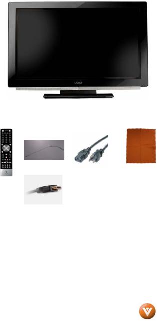
Package Contents
VIZIO VP504 FHDTV10A
VIZIO Remote Control VUR8P
HDMI Cable
VIZIO TV Stand
Premium Size VIZIO Screen Cleaning Cloth
Power Cord
This User Manual
Quick Setup Guide
Registration Card
VIP Services Brochure
2 AA Batteries for the Remote Control VIZIO Warranty and Repair Information
Version 7/2/2008 |
4 |
|
www.VIZIO.com |
VIZIO VP504 FHDTV10A User Manual
Additional Certified Accessories for the VIZIO VP504 FHDTV10A are sold separately
Wall Mounts
High Definition Cables
Extra or replacement Remote
VIZIO also offers Installation Services and Extended Warranty Services for your VIZIO VP504 FHDTV10A
To purchase or inquire about additional accessories and services for your VIZIO product, visit our web site at www.VIZIO.com or call us toll free at 888-VIZIOCE (888-849-4623)
Installation Preparation
Please read this user manual carefully before installing your VIZIO HDTV.
The power consumption of the TV is up to 700W, please use the power cord designated for TV. When an extension cord is required, use one with the correct power rating. The cord must be grounded and the grounding feature must not be defeated.
The TV should be installed on a flat surface to avoid tipping. For proper ventilation, you must allow space between the back of the TV and the wall. If you would like to mount your TV on the wall, please see below ‘Preparing Your PLASMA HDTV for Wall Mounting’ for additional information. Avoid installing the TV in places with high humidity, dust or smoke so as not to shorten the service life of the electronic components.
Install the TV in landscape orientation; any 90˚ clockwise or counter-clockwise installation may induce poor ventilation and excessive component damage.
The VIZIO VP504 FHDTV10A can either be kept on the stand base or mounted on the wall for viewing. If you choose to mount the VP504 FHDTV10A on the wall, please refer to “preparing your PLASMA HDTV for wall mounting” on page 6.
VIZIO offers professional installation services. Please contact VIZIO for more information on these services at 888-VIZIOCE (888-849-4623) or www.VIZIO.com.
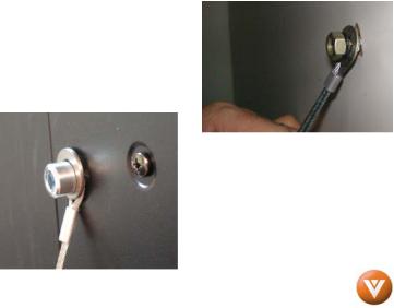
Attaching the Safety Strap
For when the VP504 FHDTV10A is not mounted on the wall with a Wall Mount, a Safety Strap has been included to attach the HDTV to the wall to reduce the chance of the HDTV being pulled over. The Safety Strap should be used with common sense practice such as ensuring that children (or adults) do not climb up, grabbing the top of the HDTV and pulling it onto themselves.
1.Fix one end of the strap to the wall. If you have a drywall finish it is preferable to fix it to a stud, using a washer underneath the screw head. If you have a solid wall you should use a lag bolt, again using a washer under the nut.
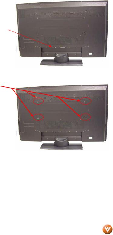
2.Fix the other end of the Safety Strap to one of the upper wall mounting holes on the back of the HDTV, using a washer under the screw head.
Version 7/2/2008 |
5 |
|
www.VIZIO.com |
VIZIO VP504 FHDTV10A User Manual
Preparing Your PLASMA HDTV for Wall Mounting
To remove the stand base
1.Unplug all of the cables and cords from your VIZIO VP504 FHDTV10A.
2.Place the VP504 FHDTV10A face down on a soft and flat surface (blanket, foam, cloth, etc) to prevent any damage to the TV.
3.Remove the cover on the stand.
4.Remove the six (6) screws holding the base to the VP504 FHDTV10A.
5.Carefully remove the stand base. 
Now, the VP504 FHDTV10A can fit securely to a mount (sold separately) by utilizing the mounting holes in the center of the back panel of the High Definition TV. Please make sure to read the instructions of your specific mount to properly hang the VP504 FHDTV10A.
The pitch of the mounting holes is 600mm horizontally and 200mm vertically.
The screw type required is metric M8, 20mm long, 1.25mm pitch. The length of the screws will depend on the thickness plate being attach to the TV; our brackets come with different length screws.
To find the perfect mount for the VIZIO VP504 FHDTV10A, browse VIZIO’s certified mount selection at www.VIZIO.com or call directly 888-VIZIOCE (888-849-4623).
Version 7/2/2008 |
6 |
|
www.VIZIO.com |

|
|
|
VIZIO VP504 FHDTV10A User Manual |
Table of Contents |
|
|
|
Chapter 1 Basic Controls and Connections.................................................................. |
9 |
||
1.1 |
Front Panel.......................................................................................................................................................... |
|
9 |
1.2 |
Side Panel Controls............................................................................................................................................. |
|
9 |
1.3 |
Rear Panel Connections ................................................................................................................................... |
|
10 |
1.4 |
Right-Side Panel Connection ............................................................................................................................ |
|
11 |
1.5 |
VIZIO Universal Remote Control....................................................................................................................... |
|
12 |
1.5.1 Insertion of Batteries in the Remote Control .............................................................................................. |
|
15 |
|
1.5.2 Remote Control Range .............................................................................................................................. |
|
15 |
|
1.5.3 VIZIO Universal Remote Control Precautions ........................................................................................... |
|
15 |
|
Chapter 2 Connecting Equipment .................................................................................. |
|
16 |
|
2.1 |
Which Video Connection Should I Use?............................................................................................................ |
|
16 |
2.2 |
Connecting Coaxial (RF) ................................................................................................................................... |
|
17 |
2.2.1 Using Your Antenna or Digital Cable for DTV............................................................................................ |
|
17 |
|
2.2.2 Using the Antenna or Cable through your VCR ......................................................................................... |
17 |
||
2.3 |
Connecting Your HDTV Set-Top Box ................................................................................................................ |
|
18 |
2.3.1 Using HDMI Input ...................................................................................................................................... |
|
18 |
|
2.3.2 Using Component Video............................................................................................................................ |
|
20 |
|
2.4 |
Connecting Your Basic Set-Top Box ................................................................................................................. |
|
21 |
2.4.1 Using Composite Video ............................................................................................................................. |
|
21 |
|
2.4.2 Using Coax (RF)........................................................................................................................................ |
|
21 |
|
2.5 |
Connecting Your DVD Player............................................................................................................................ |
|
22 |
2.5.1 Using HDMI Input ...................................................................................................................................... |
|
22 |
|
2.5.2 Using Component Video............................................................................................................................ |
|
24 |
|
2.5.3 Using S-Video (AV/S-VIDEO).................................................................................................................... |
|
25 |
|
2.5.4 Using Composite (AV) Video Input ............................................................................................................ |
|
25 |
|
2.6 |
Connecting Your VCR or Video Camera .......................................................................................................... |
|
26 |
2.7 |
Connecting an external Receiver/Amp .............................................................................................................. |
|
27 |
2.7.1 Optical Output of Audio received ............................................................................................................... |
|
28 |
|
2.8 |
Connecting a PC Computer .............................................................................................................................. |
|
29 |
2.8.1 Preset PC Resolutions............................................................................................................................... |
|
30 |
|
2.8.2 Resolution (1920x1080) through RGB (15-Pin VGA) Input........................................................................ |
30 |
||
Chapter 3 Setting Up to Watch Television................................................................... |
31 |
||
3.1 |
Basic PLASMA HDTV Start Up ......................................................................................................................... |
|
31 |
3.2 |
Watching a TV Program .................................................................................................................................... |
|
36 |
3.3 |
Adjusting Basic HDTV Settings ......................................................................................................................... |
|
37 |
3.4 |
Program Information.......................................................................................................................................... |
|
38 |
3.5 |
Information on HDTV Status ............................................................................................................................. |
|
38 |
Chapter 4 Advanced Adjustment of HDTV................................................................... |
39 |
||
4.1 |
Using the On Screen Display (OSD) ................................................................................................................. |
|
39 |
4.2 |
DTV / TV Input Picture Adjustment.................................................................................................................... |
|
40 |
4.2.1 Picture Mode ............................................................................................................................................. |
|
40 |
|
4.2.2 Brightness.................................................................................................................................................. |
|
40 |
|
4.2.3 Contrast ..................................................................................................................................................... |
|
41 |
|
4.2.4 Color .......................................................................................................................................................... |
|
41 |
|
4.2.5 Tint............................................................................................................................................................. |
|
41 |
|
4.2.6 Sharpness ................................................................................................................................................. |
|
42 |
|
4.2.7 Advanced Video Features ......................................................................................................................... |
|
42 |
|
4.2.8 Reset Picture Mode ................................................................................................................................... |
|
43 |
|
4.3 |
DTV / TV Input Audio Adjustment...................................................................................................................... |
|
44 |
4.3.1 Audio Mode ............................................................................................................................................... |
|
44 |
|
4.3.2 Equalizer.................................................................................................................................................... |
|
44 |
|
4.3.3 Balance...................................................................................................................................................... |
|
45 |
|
4.3.4 Surround.................................................................................................................................................... |
|
45 |
|
4.3.5 Digital Audio Out........................................................................................................................................ |
|
45 |
|
4.3.6 Speakers ................................................................................................................................................... |
|
45 |
|
4.3.7 Audio Out................................................................................................................................................... |
|
46 |
|
4.3.8 Lip Sync..................................................................................................................................................... |
|
46 |
|
4.3.9 Reset Audio Mode ..................................................................................................................................... |
|
46 |
|
4.4 |
DTV / TV Tuner Setup....................................................................................................................................... |
|
47 |
4.4.1 Tuner Mode ............................................................................................................................................... |
|
47 |
|
Version 7/2/2008 |
7 |
|
|
www.VIZIO.com

|
|
VIZIO VP504 FHDTV10A User Manual |
4.4.2 Auto Search............................................................................................................................................... |
47 |
|
4.4.3 Partial Channel Search.............................................................................................................................. |
48 |
|
4.4.4 Skip Channel ............................................................................................................................................. |
48 |
|
4.4.5 MTS........................................................................................................................................................... |
48 |
|
4.4.6 Time Zone ................................................................................................................................................. |
48 |
|
4.4.7 Daylight Saving.......................................................................................................................................... |
49 |
|
4.5 |
DTV / TV Input Setup ........................................................................................................................................ |
50 |
4.5.1 Language................................................................................................................................................... |
50 |
|
4.5.2 PIP (Picture-in-Picture) .............................................................................................................................. |
50 |
|
4.5.3 Adjusting Basic PIP Settings ..................................................................................................................... |
52 |
|
4.5.4 Sleep Timer ............................................................................................................................................... |
53 |
|
4.5.5 Wide .......................................................................................................................................................... |
53 |
|
4.5.6 Input Naming ............................................................................................................................................. |
54 |
|
4.5.7 CC (Closed Caption).................................................................................................................................. |
55 |
|
4.5.8 H/V Position............................................................................................................................................... |
56 |
|
4.5.9 DTV / TV Input Parental Control ................................................................................................................ |
57 |
|
4.5.10 Channel Block ......................................................................................................................................... |
57 |
|
4.5.11 US TV Rating........................................................................................................................................... |
58 |
|
4.5.12 US Movie Rating (For US) ....................................................................................................................... |
59 |
|
4.5.13 Canadian English Rating ......................................................................................................................... |
59 |
|
4.5.14 Canadian French Rating.......................................................................................................................... |
60 |
|
4.5.15 DTV Rating .............................................................................................................................................. |
60 |
|
4.5.16 Blocked Unrated Programming................................................................................................................ |
61 |
|
4.5.17 Change the Password ............................................................................................................................. |
61 |
|
4.5.18 Reset All Settings .................................................................................................................................... |
62 |
|
4.5.19 Image Cleaner ......................................................................................................................................... |
62 |
|
4.6 |
HDMI Input Picture Adjustment ......................................................................................................................... |
63 |
4.7 |
HDMI Input Audio Adjustment ........................................................................................................................... |
63 |
4.8 |
HDMI Input Setup.............................................................................................................................................. |
63 |
4.9 |
Video Input Picture Adjustment ......................................................................................................................... |
64 |
4.10 Video Input Audio Adjustment ......................................................................................................................... |
64 |
|
4.11 Video Input Setup............................................................................................................................................ |
64 |
|
4.11.1 Auto Phase (for Component input) .......................................................................................................... |
65 |
|
4.12 Video Input Parental Control ........................................................................................................................... |
66 |
|
4.13 PC Input Picture Adjustment ........................................................................................................................... |
66 |
|
4.13.1 Auto Adjust .............................................................................................................................................. |
66 |
|
4.13.2 Brightness................................................................................................................................................ |
66 |
|
4.13.3 Contrast ................................................................................................................................................... |
67 |
|
4.13.4 Color Temperature................................................................................................................................... |
68 |
|
4.13.5 H-SIZE..................................................................................................................................................... |
68 |
|
4.13.6 H. Position ............................................................................................................................................... |
68 |
|
4.13.7 V. Position ............................................................................................................................................... |
69 |
|
4.13.8 Fine Tune ................................................................................................................................................ |
69 |
|
4.14 PC Input Audio Adjustment ............................................................................................................................. |
69 |
|
4.15 PC Input Setup................................................................................................................................................ |
69 |
|
4.16 Understanding Viewing Features .................................................................................................................... |
70 |
|
4.16.1 Viewing Modes ........................................................................................................................................ |
70 |
|
Chapter 5 Maintenance and Troubleshooting............................................................. |
71 |
|
5.1 |
Maintenance...................................................................................................................................................... |
71 |
5.2 |
Troubleshooting Guide ...................................................................................................................................... |
71 |
5.3 |
Telephone & Technical Support ........................................................................................................................ |
74 |
5.4 |
Compliance ....................................................................................................................................................... |
75 |
5.5 |
FCC Class B Radio Interference Statement...................................................................................................... |
75 |
Chapter 6 Miscellaneous Information ........................................................................... |
76 |
|
6.1 |
Specifications .................................................................................................................................................... |
76 |
6.2 |
Glossary – Standard Definitions........................................................................................................................ |
77 |
6.3 |
Index ................................................................................................................................................................. |
78 |
6.4 |
Component Program Codes.............................................................................................................................. |
80 |
Version 7/2/2008 |
8 |
|
www.VIZIO.com |
VIZIO VP504 FHDTV10A User Manual
Chapter 1 Basic Controls and Connections
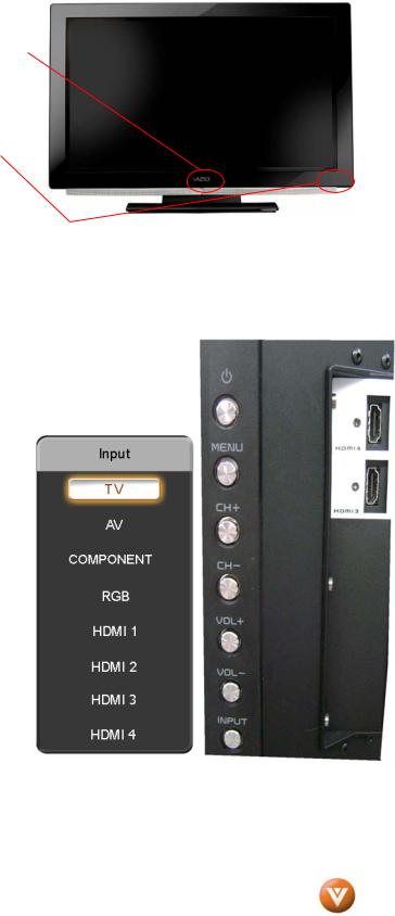
1.1 Front Panel
POWER ‘VIZIO’ LIGHT– The VIZIO name lights white when powered on and orange when powered off.
REMOTE CONTROL SENSOR – This is the window through which all of the remote control signals pass to the sensor. Point the remote control directly at this window for the best response to the remote signal.
1.2 Side Panel Controls
POWER (  ) – Switch the VP504 FHDTV10A on by pressing the button once. Press the button again to the VP504 FHDTV10A off.
MENU – This button activates the On Screen Display (OSD). If a sub-menu is active, pressing this button will return to the previous menu level.
CH + / - – Use these buttons to step up or down the TV channels. While the OSD is active, these buttons function as up and down controls in the OSD menus.
VOL + / - – Use these buttons to increase or decrease to the speaker volume. While the OSD is active, these buttons function as left and right controls in the OSD menus.
INPUT (ENTER) – Repeated pressing of this buttons steps through the input sources in the following sequence: TV, AV/S-Video, Component, RGB, HDMI 1, HDMI 2, HDMI 3 and HDMI 4. Once you have stepped through the entire sequence, you will return to the beginning.
Additionally, when the OSD is active, this button confirms the menu function to be adjusted. When the OSD is not active, pressing this button will display the current input mode.
Version 7/2/2008 |
9 |
|
www.VIZIO.com |
VIZIO VP504 FHDTV10A User Manual
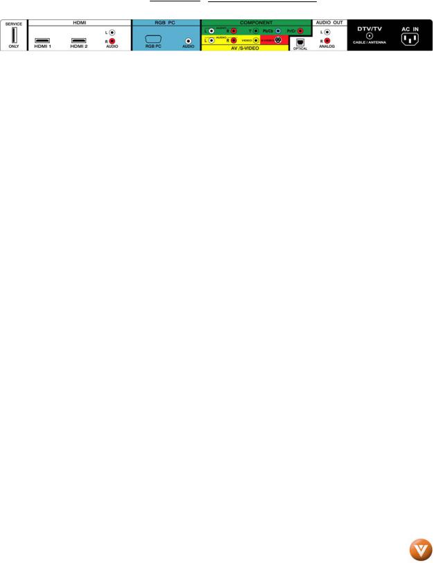
1.3 Rear Panel Connections
1 |
|
|
|
3 |
|
|
|
4 |
|
|
|
5 |
|
8 |
|
9 |
|
10 |
||||||
|
|
|
|
|
|
|
|
|
|
|
|
|
|
|
|
|
|
|
|
|
|
|
|
|
|
|
|
|
|
|
|
|
|
|
|
|
|
|
|
|
|
|
|
|
|
|
|
|
|
|
|
|
|
|
|
|
|
|
|
|
|
|
|
|
|
|
|
|
|
|
|
|
|
|
|
|
|
|
|
|
|
|
|
|
|
|
|
|
|
|
|
|
|
|
|
|
|
|
|
|
|
|
|
|
|
|
|
|
|
|
|
|
|
|
|
|
|
|
|
|
|
|
|
|
|
|
|
|
|
|
|
|
|
6 |
|
|
|
7 |
|
2 |
|
|
|
|
|||||
|
|
|
|
|
|
|
|
||
|
|
|
|
|
|
|
|
|
|
1.SERVICE – This custom communication port is for factory service only. Use of this input for any purpose other than factory authorized service will void the manufacturer’s warranty of this equipment.
2.HDMI 1 – Connect the primary source for digital video such as a DVD multimedia player or set top box through this all digital connector. The white color band on the rear of the TV indicates this connection.
3.HDMI 2 – Connect a secondary source for digital video such as a DVD multimedia player or set top box through this all digital connector. The white color band on the rear of the TV indicates this connection. For users who want to connect to a DVI enabled device, use a DVI-HDMI cable and connect the Analog Audio output of the device to the L+R AUDIO here. . Your VIZIO Certified HDMI and HDMI-DVI cables are available for purchase from www.VIZIO.com or by calling 888-VIZIOCE (888-849-4623).
4.RGB PC – Connect the video and audio from a computer here. The blue color band on the rear of the TV indicates this connection. A 1/8” plug stereo cable is needed to connect the audio out from the computer to the connector in the rear of the TV for audio from computer.
5.COMPONENT (YPb/CbPr/Cr with Audio L/R) – Connect the source for component video devices such as a DVD Player or set top box here. From left to right, use white for left audio and red for right audio inputs, green for Y, blue for Pb (or Cb) and red for Pr (or Cr). The green color band on the rear of the TV indicates this connection.
6.AV/S-VIDEO IN – Connect the primary source for composite video devices, such as a VCR or video game. Use the white and red connectors to connect the external audio from the same source, then use the S-Video or yellow connector to connect the external video from the same source. The S-Video, if connected, will take priority over AV RCA (yellow) connector. The yellow color band on the rear of the TV indicates this connection.
7.OPTICAL AUDIO OUT – When an audio signal is associated with an input which is selected for viewing, the audio associated with the programming will be available on this SPDIF Optical connector for connection to your home theatre system. The white color band on the rear of the TV indicates this connection.
8.ANALOG AUDIO OUT – Connect the audio from the PLASMA HDTV to an external device, such as a home theater system, external amplifier or stereo. Speakers cannot be connected directly to here. The white color band on the rear of the TV indicates this connection.
9.DTV – Connect to an antenna or digital cable (out-of-the-wall, not from Cable Box) for Digital TV.*
10.AC IN – Plug-in the supplied AC Power Cord here.
* For digital TV stations in your area visit www.antennaweb.org.
Version 7/2/2008 |
10 |
|
www.VIZIO.com |
VIZIO VP504 FHDTV10A User Manual
1.4 Right-Side Panel Connection
1.HDMI 3 - Connect the third source for digital video such as a DVD multimedia player or set top box through this all digital connector. The white color band on the side of the TV indicates this connection.
2. HDMI 4 - Connect the fourth source for digital video such as a |
2 |
DVD multimedia player or set top box through this all digital connector. The white color band on the side of the TV indicates this connection.
1
Version 7/2/2008 |
11 |
|
www.VIZIO.com |
VIZIO VP504 FHDTV10A User Manual
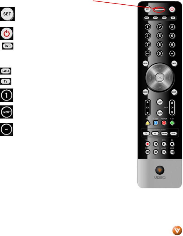
1.5 VIZIO Universal Remote Control
The VIZIO Universal Remote Control is a comprehensive remote that can be used to control up to four different components. The remote button functions are explained on the following pages.
Remote LED – Blinks when the remote operates.
This button starts all programming of the Remote Control.
Press this button to turn the TV on from the Standby mode.
Press it again to return to the Standby mode.
This button selects a programmed DVD player.
 This button selects a programmed Audio Receiver/Amp/Home Theatre System.
This button selects a programmed cable TV set-top box or a satellite TV set-top box.
This button has been pre-programmed to select the codes to operate the VIZIO HDTV.
Use these buttons to select a channel or enter a password.
This button allows the user to cycle through the inputs.
This DASH button is for the DTV mode. When selecting a digital channel directly use this button for the separation of main and subchannels. For example, channel 28-2 would be selected by the button sequence 2 8 DASH 2.
NOTE: This is a programmable remote supporting up to 4 devices (see TV, VCR, CABLE, DVD buttons at the top of the remote). If the remote is not working with your VIZIO TV, press the TV button on the remote to set the functions back to TV.
Version 7/2/2008 |
12 |
|
www.VIZIO.com |

VIZIO VP504 FHDTV10A User Manual
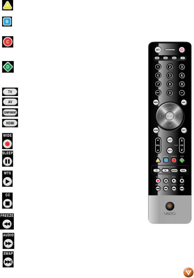
Use this button for the On-Screen Display (OSD) menus.
This button displays the image and system information display.
Use the NaVigation Wheel to operate the On-Screen
Display (OSD) after it has been activated by pressing the
MENU button.
Use the OK button to select your chosen option in On-
Screen Display (OSD) menus.
GUIDE – This button displays program information. Note: this button is only functional for DTV.
EXIT – This button exits the On-Screen Display (OSD) menus.
VOL (+ or -) – These buttons turn the volume up or down.
LAST – This button recalls the previously viewed channel.
MUTE – This button turns the sound on and off.
CH (+ or -) – These buttons change the channels up or down.
Version 7/2/2008 |
13 |
|
www.VIZIO.com |
VIZIO VP504 FHDTV10A User Manual
When CABLE is selected and the code to match your Cable (or Satellite) Box has been entered, this button will operate the Cable (or Satellite) Box the same as this button on your Cable (or Satellite) Remote. When TV is selected, this button activates Picture-in-Picture mode.
When CABLE is selected and the code to match your Cable (or Satellite) Box has been entered, this button will operate the Cable (or Satellite) Box the same as this button on your Cable Remote. When TV is selected, press this button to select the size of the PIP screen from one of the
following: small, medium or large
When CABLE is selected and the code to match your Cable Box (or Satellite) has been entered, this button will operate the Cable Box (or Satellite) the same as this button on your Cable Remote (or Satellite).
When TV is selected, press the button to choose the PIP input. Note: The TV must be in PIP mode for this button to be functional.
When CABLE is selected and the code to match your Cable Box (or Satellite) has been entered, this button will operate the Cable Box (or Satellite)the same as this button on your Cable Remote (or Satellite).
When TV is selected, this button is used to select the channels within the PIP screen when DTV/TV is the PIP input selected
Press this button to select TV programming.
Repeated pressing of this button will switch between AV1 and AV2 inputs.
Repeated pressing of this button will switch between Component 1 and Component 2 inputs.
Repeated pressing of this button will switch between HDMI 1, HDMI 2, HDMI 3 and HDMI 4 inputs.
This button cycles through the available screen formats. The options are Wide, Normal, Zoom, Panoramic. Note: in RGB/PC mode the options are 4:3 and 16:9. This button also starts recording when using the remote to control your Cable/Satellite Box or VCR.
This button allows the user to select the sleep options by adjusting the timer in 30 minute increments up to 120 minutes. This button also Pauses playback when using the remote to control your Cable/Satellite Box or VCR.
This button will select the MTS options of Stereo, SAP or Mono in standard TV mode and alternate audio channels, where available, in DTV mode. This button also starts Playback when using the remote to control your Cable/Satellite Box or VCR.
This button will select the Closed Caption mode. The options are OFF, CC1, CC2, CC3, CC4 and if Digital Cable Service is the signal; you would get Service1 through Service6, depending on your local company . This button also Stops playback/recording when using the remote to control your Cable/Satellite Box or VCR.
Press this button to “Freeze-Frame” the current screen. Press this button again the continue playing. This button also skips to the previous chapter when using the remote to control your
Cable/Satellite Box or DVD Player.
Press this button to switch the audio from the main screen to the sub-screen while in PIP or POP mode.
While in PIP/POP mode; pressing SWAP will switch the displays from the main screen to the sub-screen or vice versa.
Version 7/2/2008 |
14 |
|
www.VIZIO.com |
VIZIO VP504 FHDTV10A User Manual
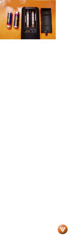
1.5.1 Insertion of Batteries in the Remote Control
Insert two AA batteries into the remote control. Make sure that you match the (+) and (-) symbols on the batteries with the (+) and (-) symbols inside the battery compartment. Re-attach the battery cover.
Precautionary Tips for Inserting the Batteries:
Only use the specified AA batteries.
Do not mix new and old batteries. This may result in cracking or leakage that may pose a fire risk or lead to personal injury.
Inserting the batteries incorrectly may also result in cracking or leakage that may pose a fire risk or lead to personal injury.
Dispose of the batteries in accordance with local laws and regulations.
Keep the batteries away from children and pets.
1.5.2 Remote Control Range
Point the remote control at the remote control sensor to transmit the commands. Do not place any obstacles between the remote control and the receiver window.
The effective range of the remote control is approximately 30 feet (10 meters) from the front of the receiver window, 30° to the left and right, 20° up and down.
1.5.3 VIZIO Universal Remote Control Precautions
The remote control should be kept dry and away from heat sources. Avoid humidity.
If the TV responds erratically to the remote control or does not respond at all, check the batteries. If the batteries are low or exhausted, replace them with fresh batteries.
When not using the remote control for a long period of time, remove the batteries. Do not take the batteries apart, heat them, or throw them into a fire.
Do not subject the remote control to undue physical stress, such as striking or dropping it.
Do not attempt to clean the remote control with a volatile solvent. Wipe it with a clean, damp cloth.
Version 7/2/2008 |
15 |
|
www.VIZIO.com |
VIZIO VP504 FHDTV10A User Manual
Chapter 2 Connecting Equipment
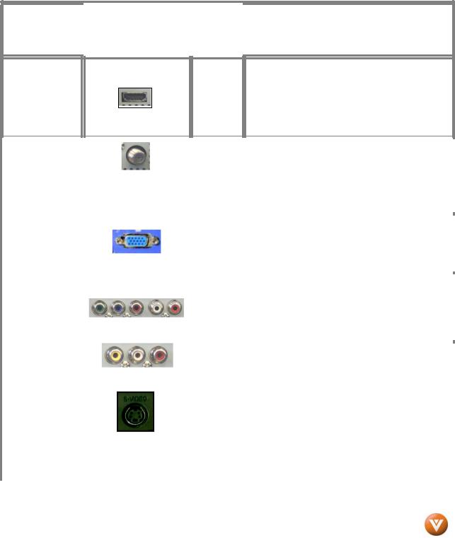
2.1 Which Video Connection Should I Use?
The VIZIO VP504 FHDTV10A has six different ways to connect your video equipment from a basic connection to the most advanced for digital displays.
|
|
|
|
|
|
|
|
|
|
|
|
|
|
|
|
|
|
|
|
Rear |
|
|
|
|
|
|
|
Connection |
|
|
Connector |
|
Panel |
|
|
Description |
|
|
|
|
Quality (type) |
|
|
|
Color |
|
|
|
|
||
|
|
|
|
|
|
|
|
|
|
|
||
|
|
|
|
|
|
|
Codes |
|
|
|
|
|
|
|
|
|
|
|
|
|
|
|
|
|
|
Best (digital)
HDMI (High-Definition Multimedia Interface) - It is the first and only industry-supported, uncompressed, all-digital audio/video interface. HDMI provides an
White interface between any audio/video source, such as a set-top box, DVD player, or A/V receiver and an audio and/or video monitor, such as a digital television (DTV), over a single cable.
|
Best |
|
|
|
|
|
|
|
|
|
|
|
DTV Coaxial RF. When used for MPEG2 encoded |
|
|
|
|
|
|
|
|
|
|
|
|||||
|
|
|
|
|
|
|||||||||
|
(digital) |
|
|
|
|
|
|
|
|
|
|
|
bit streams from ATSC broadcast programming, this |
|
|
|
|
|
|
|
|
|
|
|
input takes advantage of the High Definition content. |
||||
|
- - - - - - - - - - - - |
|
|
|
|
|
|
|
|
|
Black |
|
||
|
|
|
|
|
|
|
|
|
|
|
- - - - - - - - - - - - - - - - - - - - - - - - - - - - - - - - - - - - - - |
|||
|
Good |
|
|
|
|
|
|
|
|
|
|
|
||
|
|
|
|
|
|
|
|
|
|
TV Coaxial RF. This is the connection for standard |
||||
|
(analog) |
|
|
|
|
|
|
|
|
|
NTSC TV using antenna or cable. |
|||
|
|
|
|
|
|
|
|
|
|
|
|
|
|
|
|
|
|
|
|
|
|
|
|
|
|
|
|
RGB PC (VGA) – This video input has separate red, |
|
|
|
|
|
|
|
|
|
|
|
|
|
|
||
|
Best |
|
|
|
|
|
|
|
Blue |
|
green and blue |
color components. The signal |
||
|
(analog) |
|
|
|
|
|
|
|
|
|
|
carries horizontal and vertical sync information on |
||
|
|
|
|
|
|
|
|
|
|
the green signal. |
This is most commonly used for |
|||
|
|
|
|
|
|
|
|
|
|
|
|
|
PC input. |
|
|
|
|
|
|
|
|
|
|
|
|
|
|
|
|
|
|
|
|
|
|
|
|
|
|
|
|
|
Component - The video signal is separated into |
|
|
|
|
|
|
|
|
|
|
|
|
|
|
||
|
Better |
|
|
|
|
|
|
|
|
|
|
|
three signals, one containing the black-and-white |
|
|
|
|
|
|
|
|
|
|
|
Green |
|
information and the other two containing the color |
||
|
|
|
|
|
|
|
||||||||
|
(analog) |
|
|
|
|
|
|
|
|
|
|
information. This enhancement over S-Video takes |
||
|
|
|
|
|
|
|
|
|
|
|
|
|||
|
|
|
|
|
|
|
|
|
|
|
|
|
advantage of the superior picture provided by |
|
|
|
|
|
|
|
|
|
|
|
|
|
|||
|
|
|
|
|
|
|
|
|
|
|
|
|
progressive scan DVD players and HDTV formats. |
|
|
|
|
|
|
|
|
|
|
|
|
|
|
|
|
|
|
|
|
|
|
|
|
|
|
|
|
|
Composite - The complete video signal is carried |
|
|
|
|
|
|
|
|
|
|
|
|
|
|
||
|
|
|
|
|
|
|
|
|
|
|
|
|
through this single pin connector. This is the most |
|
|
|
|
|
|
|
|
|
|
|
|
|
|
commonly used video connection. |
|
|
|
|
|
|
|
|
|
|
|
|
|
|||
|
Good |
|
|
|
|
|
|
|
|
|
Yellow, |
|
S-Video - The video signal is separated into two |
|
|
|
|
|
|
|
|
|
and |
|
signals, one containing the black-and-white |
||||
|
(analog) |
|
|
|
|
|
|
|
|
|
|
|||
|
|
|
|
|
|
|
|
Red |
|
information and the other containing the color |
||||
|
|
|
|
|
|
|
|
|
|
|
|
information. Separating the color in this way avoids |
||
|
|
|
|
|
|
|
|
|
|
|
|
|
‘cross color’ effects where closely spaced black and |
|
|
|
|
|
|
|
|
|
|
|
|
|
|
white lines are erroneously displayed in color. It also |
|
|
|
|
|
|
|
|
|
|
|
|
|
|
enables text to be displayed more sharply. |
|
|
|
|
|
|
|
|
|
|
|
|
|
|
|
|
Note: For more info refer to the Quick Start Guide
Version 7/2/2008 |
16 |
|
www.VIZIO.com |
VIZIO VP504 FHDTV10A User Manual
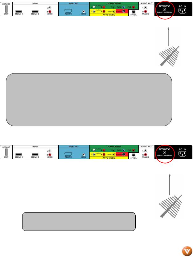
2.2 Connecting Coaxial (RF)
2.2.1Using Your Antenna or Digital Cable for DTV
1.Turn off the power to the HDTV.
2.Connect the coaxial (RF) connector from your antenna or digital cable (out-of-the-wall, not from the Cable Box) to the DTV/TV CABLE/ANTENNA connector on the rear of the HDTV.
3.Turn on the power to the HDTV.
4.Select DTV using the INPUT button on the remote or side of the HDTV, or directly by pressing the TV button on the Remote Control.
Note:
a)Not all digital TV broadcasts are High Definition (HD). Refer to the program guides, or consult your cable, satellite or TV station operator.
b)Digital broadcasts are not available in all areas. Refer to www.antennaweb.org for detailed information.
c)Make sure the antenna and coaxial cable are correctly grounded.
d)For Professional antenna installation contact us at www.VIZIO.com or call 1-888-VIZIOCE (1-888-849-4623).
2.2.2Using the Antenna or Cable through your VCR
1.Turn off the power to the HDTV and VCR.
2.Connect the “Output to TV”, “RF Out” or “Antenna Out” connector on the rear of your VCR to the DTV/TV CABLE/ANTENNA connector at the rear of the HDTV.
3.Turn on the power to the HDTV and VCR.
4.Select TV using the INPUT button on the remote or side of the HDTV, or directly by pressing the TV button on the Remote Control.
Note: If you have an off-air antenna or cable TV, connect it to the “Antenna In” connector on the rear of your VCR.
Version 7/2/2008 |
17 |
|
www.VIZIO.com |
VIZIO VP504 FHDTV10A User Manual
2.3 Connecting Your HDTV Set-Top Box
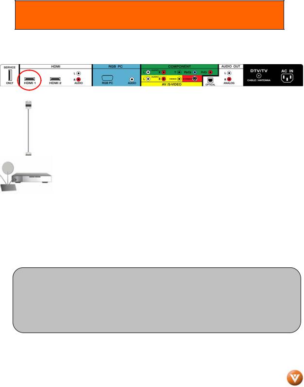
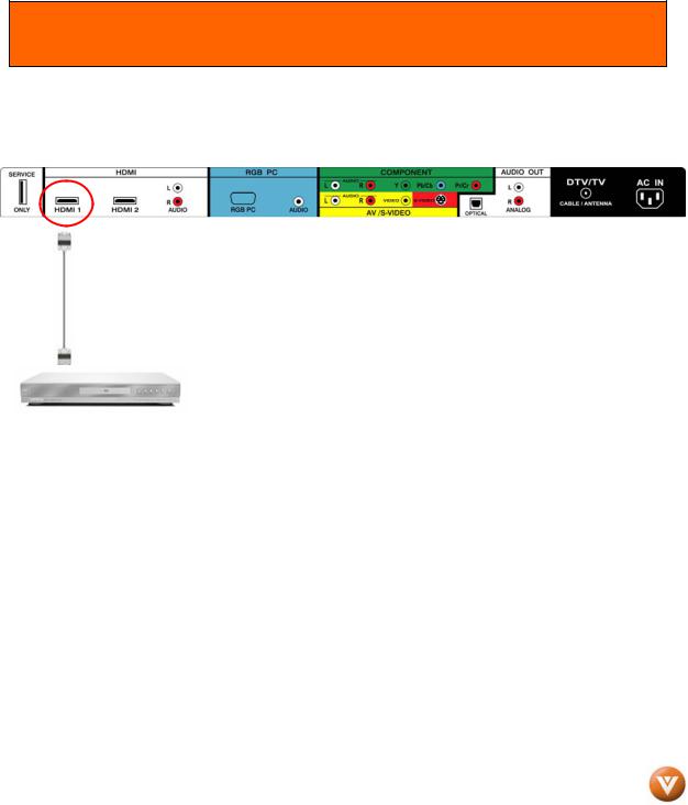
2.3.1 Using HDMI Input
HDTV Set-Top Boxes that have a HDMI digital interface should be connected to the HDMI input of the PLASMA HDTV for optimal results.
Note: To maintain the display quality, use a VIZIO certified HDMI cable. Length is available up to 10 meters. See www.vizioce.com or call 1-888-VIZIOCE (1-888-849-4623) for details.
Connecting your HDTV Set-Top Box (Best):
1.Turn off the power to the HDTV and HDTV Set-Top Box.
2.Connect a HDMI cable to the HDMI output of your HDTV Set-Top Box and the other end to the HDMI Input (white color area) at the rear of the HDTV.
3.Turn on the power to the HDTV and HDTV Set-Top Box.
4.Select HDMI using the INPUT button on the remote or side of the HDTV, or directly by pressing the HDMI button on the Remote Control.
Note:
a)The HDMI input on the HDTV supports High-bandwidth Digital Content Protection (HDCP). HDCP encrypts the transmission between the video source and the digital display for added security and protection.
b)Refer to your HDTV Set-Top Box user manual for more information about the video output requirements of the product or consult your cable or satellite operator.
Version 7/2/2008 |
18 |
|
www.VIZIO.com |
VIZIO VP504 FHDTV10A User Manual
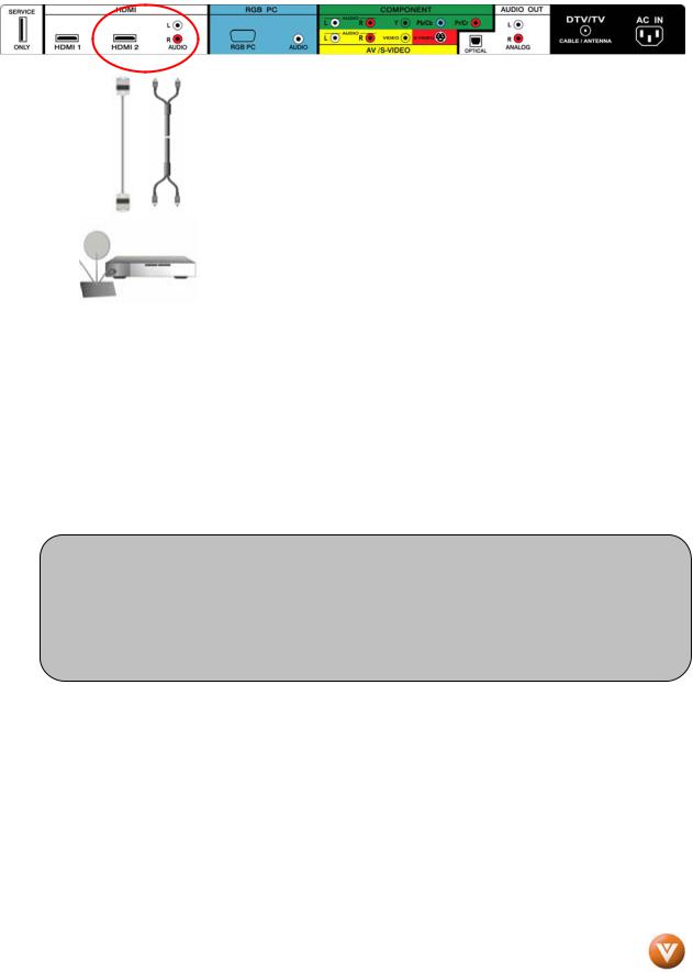
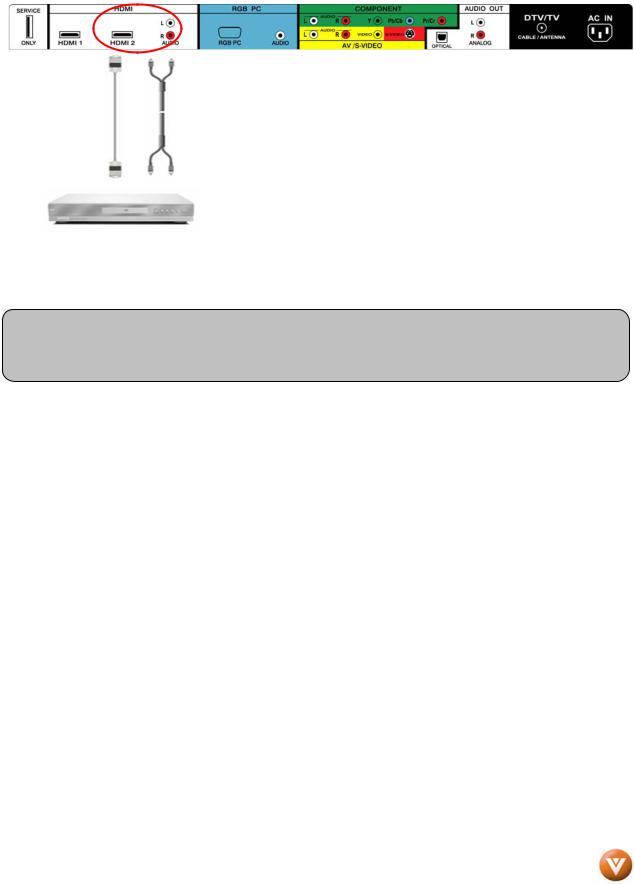
For HDTV Set-Top Boxes with DVI:
1.Turn off the power to the HDTV and HDTV Set-Top Box.
2.Using a HDMI-DVI cable, connect the DVI end to your HDTV Set-Top Box and the HDMI end to the HDMI 2 Input (white color area) at the rear of the HDTV.
3.Using an audio cable (white and red connectors), connect the cable to the audio output connectors associated with the DVI output on your HDTV Set-Top Box and connect the other end to the audio connectors associated with the HDMI input (white area) at the rear of the HDTV.
4.Turn on the power to the HDTV and HDTV Set-Top Box.
5.Select HDMI 2 using the INPUT button on the remote or side of the HDTV, or directly by pressing the HDMI button on the Remote Control.
Note:
a)The HDMI input on the HDTV supports High-bandwidth Digital Content Protection (HDCP). HDCP encrypts the transmission between the video source and the digital display for added security and protection.
b)Refer to your HDTV Set-Top Box user manual for more information about the video output requirements of the product or consult your cable or satellite operator.
Version 7/2/2008 |
19 |
|
www.VIZIO.com |
VIZIO VP504 FHDTV10A User Manual
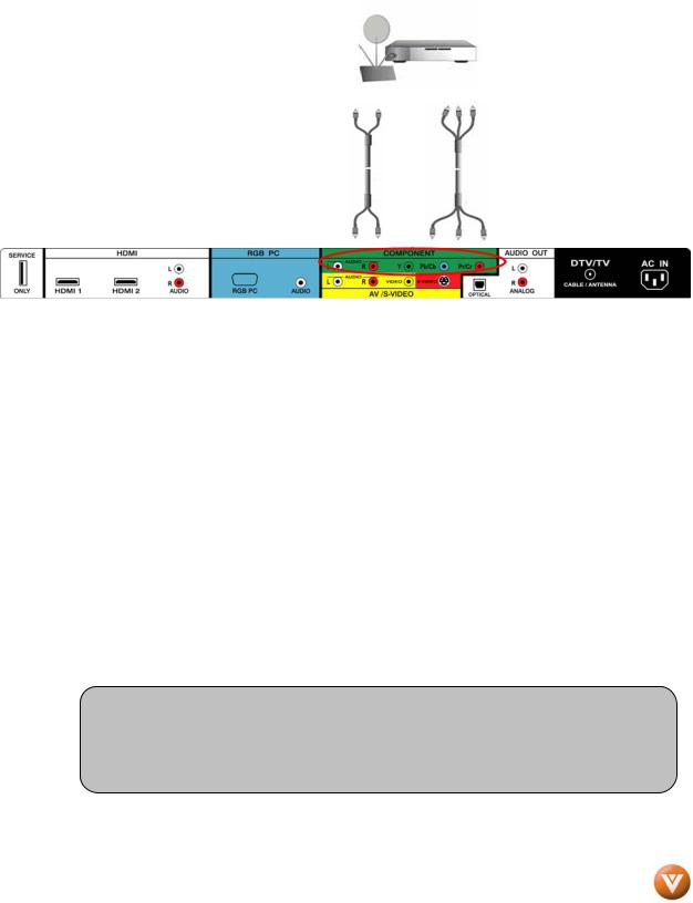
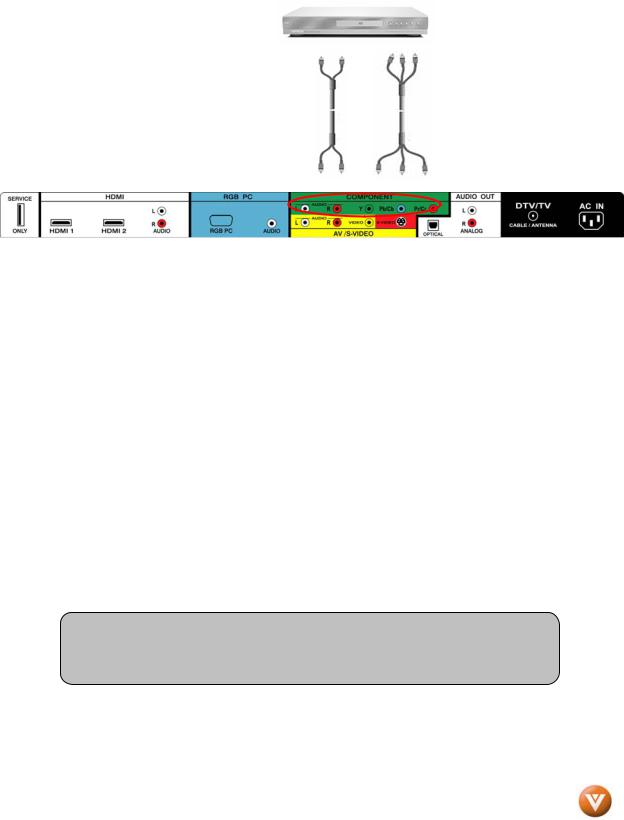
2.3.2 Using Component Video
Connecting your HDTV Set-Top Box (Better):
1.Turn off the power to the HDTV and HDTV Set-Top Box.
2.Connect the Y (green color) connector on your HDTV Set-Top Box to the corresponding Y (green color) connector in the Component group (green color area - row of connectors nearest to you when viewing from the rear of the TV) at the rear of the HDTV.
3.Connect the Pb (blue color) connector on your HDTV Set-Top Box to the corresponding Pb (blue color) connector in the Component input (green color area - row of connectors nearest to you when viewing from the rear of the TV) at the rear of the HDTV.
4.Connect the Pr (red color) connector on your HDTV Set-Top Box to the corresponding Pr (red color) connector in the Component input (green color area - row of connectors nearest to you when viewing from the rear of the TV) at the rear of the HDTV.
5.Using an audio cable (white and red connectors), connect the cable to the audio output connectors associated with the Component output on your HDTV Set-Top Box and connect the other end to the audio connectors associated with the Component1 input (green color area) at the rear of the HDTV.
6.Turn on the power to the HDTV and HDTV Set-Top Box.
7.Select Component using the INPUT button on the remote or side of the HDTV, or directly by pressing the Component button on the Remote Control.
Note:
a)Refer to your HDTV Set-Top Box user manual for more information about the video output requirements of the product or consult your cable or satellite operator.
Version 7/2/2008 |
20 |
|
www.VIZIO.com |
VIZIO VP504 FHDTV10A User Manual
2.4 Connecting Your Basic Set-Top Box
2.4.1 Using Composite Video
1.Turn off the power to the HDTV and Set-Top Box.
2.Using the AV Cable, connect the Video (yellow color) connector on your Set-Top Box to the
corresponding Video (yellow color)
connector in the AV input (yellow color area) at the rear of the HDTV.
3.Using the white and red connectors, connect the cable to the audio output connectors associated with the Video output on your Set-Top Box and connect the other end to the audio connectors associated with the AV input (yellow color area) at the rear of the HDTV.
4.Turn on the power to the HDTV and Set-Top Box.
5.Select AV using the INPUT button on the remote or side of the HDTV, or directly by pressing the AV button on the Remote Control.
2.4.2 Using Coax (RF)
1.Turn off the power to the HDTV and Set-Top Box.
2.Using a Coax (RF) cable, connect one end to the TV OUT (RF) on your Set Top Box and the other end to the DTV/TV input at the rear of the HDTV.
3.Turn on the power to the HDTV and Set-Top Box.
4.Select TV using the INPUT button on the remote or side of the HDTV, or directly by pressing the TV button on the Remote Control.
Note: Refer to your Set Top Box user manual for more information about selecting the video or RF output of the product.
Version 7/2/2008 |
21 |
|
www.VIZIO.com |
VIZIO VP504 FHDTV10A User Manual
2.5 Connecting Your DVD Player
You have several options for connecting your DVD player to your VP504 FHDTV10A; HDMI, Component, AV (S-Video or Composite) inputs. Based on your configuration, you can decide which option is right for you.
2.5.1 Using HDMI Input
DVD players that have a digital interface such as HDMI (High Definition Multimedia Interface) should be connected to the HDMI input of the VIZIO VP504 FHDTV10A for optimal results.
Note: To maintain the display quality, use a VIZIO certified HDMI cable available up to 10 meters. See www.VIZIOCE.com or call 1-888-VIZIOCE (1-888-849-4623) for details.
Connecting your DVD Player (Best):
1.Turn off the power to the HDTV and DVD player.
2.Connect a HDMI cable to the HDMI output of your DVD player and the other end to the HDMI1 Input (white color area) at the rear of the HDTV.
3.Turn on the power to the HDTV and DVD player.
4.Select HDMI1 using the INPUT button on the remote or side of the HDTV, or directly by pressing the HDMI button on the Remote Control.
5.If HDMI1 is being used, connect to either HDMI 2 or HDMI 3 as the input and follow steps 1 through 3; and then select the corresponding HDMI input step 4.
Version 7/2/2008 |
22 |
|
www.VIZIO.com |
VIZIO VP504 FHDTV10A User Manual
For DVD Players with DVI:
1.Turn off the HDTV and DVD player.
2.Using a HDMI-DVI cable, connect the DVI end to your DVD player and the HDMI2 end to the HDMI Input (white color area) at the rear of the HDTV.
3.Connect an audio cable (white and red connectors) to the audio output connectors associated with the DVI output of the DVD player and connect the other end to the audio connectors by the HDMI input (white area) at the rear of the HDTV.
4.Turn on the power to the HDTV and your DVD player.
5.Select HDMI 2 using the INPUT button on the remote or side of the HDTV, or directly by pressing the HDMI button on the Remote.
Note: Refer to your DVD player user manual for more information about the video output requirements of the product.
Version 7/2/2008 |
23 |
|
www.VIZIO.com |
VIZIO VP504 FHDTV10A User Manual
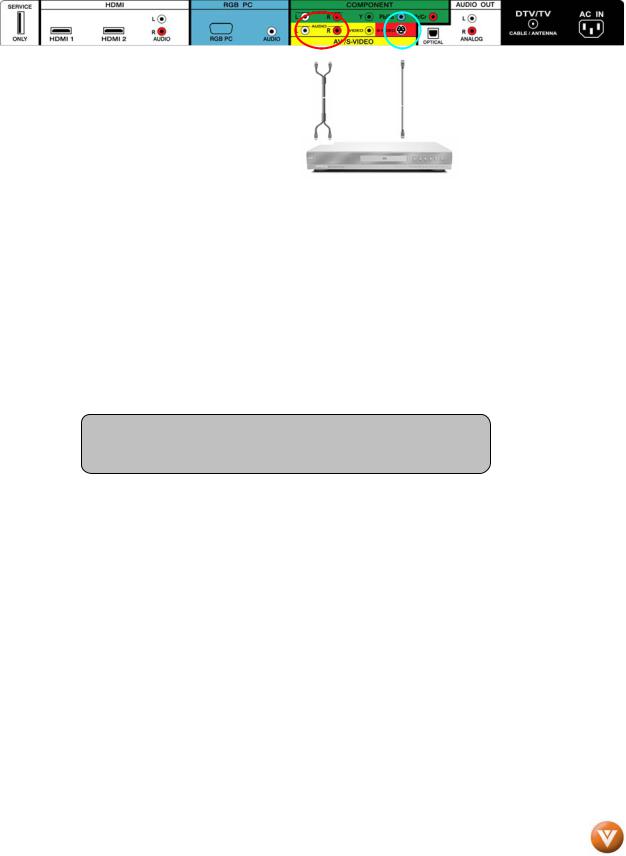
2.5.2 Using Component Video
Connecting your DVD Player (Better):
1.Turn off the power to the HDTV and DVD player.
2.Connect the Y (green color) connector on your DVD player to the corresponding Y (green color) connector in the Component input (green color area - row of connectors nearest to you when viewing from the rear of the TV) at the rear of the HDTV.
3.Connect the Pb (blue color) connector on your DVD player to the corresponding Pb (blue color) connector in the Component input (green color area - row of connectors nearest to you when viewing from the rear of the TV) at the rear of the HDTV.
4.Connect the Pr (red color) connector on your DVD player to the corresponding Pr (red color) connector in the Component input (green color area - row of connectors nearest to you when viewing from the rear of the TV) at the rear of the HDTV.
5.Using an audio cable (white and red connectors), connect the cable to the audio output connectors associated with the Component output on your DVD player and connect the other end to the audio connectors associated with the Component input (green color area) at the rear of the HDTV.
6.Turn on the power to the HDTV and DVD player.
7.Select Component using the INPUT button on the remote or side of the HDTV, or directly by pressing the Component button on the Remote Control.
Note:
a)Refer to your DVD player user manual for more information about the video output requirements of the product.
Version 7/2/2008 |
24 |
|
www.VIZIO.com |
VIZIO VP504 FHDTV10A User Manual
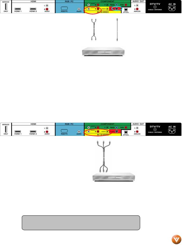
2.5.3 Using S-Video (AV/S-VIDEO)
Connecting your DVD Player (Good):
1.Turn off the power to the HDTV and DVD player.
2.Connect the S-Video jack on the rear of your DVD player to the S-Video jack in the AV/S-VIDEO input (yellow/red area) at the rear of the HDTV.
3.Connect an audio cable (white and red connectors) to the audio output connectors associated with the S-Video output on your DVD player and connect the other end to the audio connectors associated with the AV input (yellow/red area) at the rear of the HDTV.
4.Turn on the power to the HDTV and DVD player.
5.Select AV using the INPUT button on the remote or side of the HDTV, or directly by pressing the AV button on the Remote Control.
2.5.4 Using Composite (AV) Video Input
Connecting your DVD Player (Good) :
Turn off the power to the HDTV and DVD player.
1.Connect the Video (yellow color) connector on your DVD player to the Video (yellow color) connector in the AV/S-VIDEO input (yellow/red color area - row of connectors furthest from you when viewing from the rear of the HDTV) at the rear of the HDTV.
2.Connect the R (red color) and L (white
color) audio connectors on your DVD player to the corresponding R (red color) and L (white color) audio input connectors in the AV input (yellow/red color area - row of connectors furthest from you when viewing from the rear of the TV) on the rear of the HDTV.
3.Turn on the power to the HDTV and DVD Player.
4.Select AV using the INPUT button on the remote or side of the HDTV, or directly by pressing the AV button on the Remote Control.
Note: Refer to your DVD player user manual for more information about the video output requirements of the product.
Version 7/2/2008 |
25 |
|
www.VIZIO.com |
VIZIO VP504 FHDTV10A User Manual
2.6 Connecting Your VCR or Video Camera
1.Turn off the HDTV and VCR or Video Camera.
2.Connect the S-Video jack on the rear of your VCR or Video Camera to the S-Video jack in the AV input (yellow/red area) at the rear of the HDTV.
3.Connect an audio cable (white and red connectors) cable to the audio output connectors associated with the S-Video output on your VCR or Video Camera and connect the other end to the audio connectors associated with the AV input (yellow/red area) at the rear of the HDTV.
4.Turn on the power to the HDTV and VCR or Video Camera.
5.Select AV using the INPUT button on the remote or side of the HDTV, or directly by pressing the AV button on the Remote Control.
Note: Refer to your VCR or Video Camera user manual for more information about the video output requirements of the product.
Version 7/2/2008 |
26 |
|
www.VIZIO.com |
VIZIO VP504 FHDTV10A User Manual
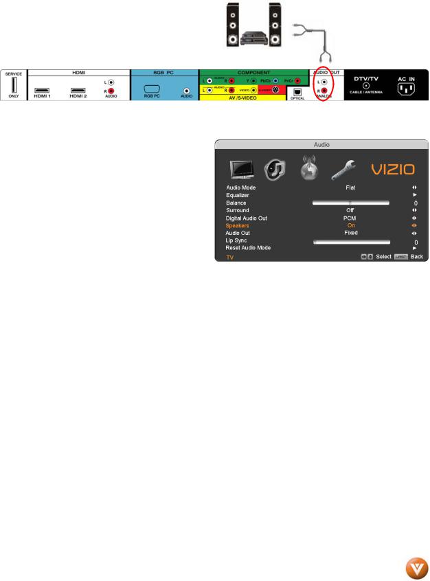
2.7 Connecting an external Receiver/Amp
1.Turn off the power to the PLASMA HDTV and Receiver/Amp.
2.Using an audio cable (white and red connectors), connect the cable to the audio input connectors on the Receiver/Amp and connect the other end to the ANALOG OUT (white area) audio connectors at the rear of the PLASMA HDTV.
3.Turn on the power to the PLASMA HDTV and Receiver/Amp.
4.Then press the MENU button on the remote control to open the OnScreen Display (OSD) menu.
5.Press the  on the remote control to select the Audio Adjust menu.
6.Press the  on the remote control to select SPEAKERS.
7.Press the  on the remote control to select OFF so that the sound from the PLASMA HDTV will now be routed through your Receiver/Amp system.
Version 7/2/2008 |
27 |
|
www.VIZIO.com |
VIZIO VP504 FHDTV10A User Manual
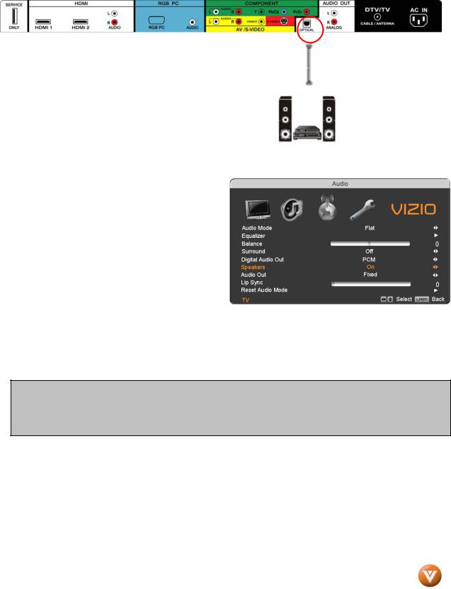
2.7.1 Optical Output of Audio received
If your sound system has a SPDIF (optical) digital audio input you can connect it to the optical AUDIO OUT (white area) at the rear of the VP504 HDTV10A.
1.Turn off the power to the PLASMA HDTV and Receiver/Amp.
2.Using an SPDIF cable, connect the cable to the audio input connector on the Receiver/Amp and connect the other end to the OPTICAL OUT (white area) audio connectors at the rear of the PLASMA HDTV.
3.Turn on the power to the PLASMA HDTV and Receiver/Amp.
4.Then press the MENU button on the remote control to open the On-Screen Display (OSD) menu.
5.Press the  on the remote control to select the Audio Adjust menu.
6.Press the  on the remote control to select SPEAKERS.
7.Press the  on the remote control to select OFF so that the sound from the
PLASMA HDTV will now be routed through your Receiver/Amp system.
Press the LAST key once to return to the previous screen or repeatedly to return to your program if task has been completed.
Note:
a)Refer to your Receiver/Amp user manual to select the corresponding audio input.
b)The audio output is not amplified and cannot be connected directly to external speakers.
Version 7/2/2008 |
28 |
|
www.VIZIO.com |
VIZIO VP504 FHDTV10A User Manual
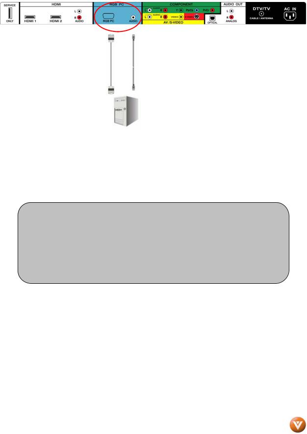
2.8 Connecting a PC Computer
1.Turn off the power to the HDTV and PC Computer.
2.Connect a 15-pin D-Sub RGB (VGA) cable to the RGB output of your pc computer and the other end to the RGB PC input (blue area) at the rear of the HDTV.
3.Connect the Audio Out on your pc computer to the RGB PC Audio input (blue area) at the rear of the HDTV.
4.Turn on the HDTV and PC Computer.
5.Select RGB using the INPUT button on the remote or side of the HDTV.
Note:
a)For the best picture quality when connecting a pc computer through RGB PC, set your pc computer timing mode to VESA 1920x1080 at 60Hz. Please refer to the pc or graphic card’s user guide for additional information on how to set the timing mode and the video output requirements of the product.
b)A RGB (VGA) cable and stereo mini jack cable are not included and can be purchased at an electronics store.
Version 7/2/2008 |
29 |
|
www.VIZIO.com |

VIZIO VP504 FHDTV10A User Manual
2.8.1 Preset PC Resolutions
If connecting to a PC through the RGB PC input, set the TV timing mode to VESA 1920x1080 at 60Hz for best picture quality (refer to the graphic card’s user guide for questions on how to set this timing mode). Please see the table below for the factory preset resolutions.
Resolution |
Refresh (Hz) |
H.Freq (kHz) |
V.Freq (Hz) |
H.Sync |
V.Sync |
Pixel Freq (MHz) |
640x480 |
60 |
31.47 |
59.94 |
N |
N |
25.18 |
|
|
|
|
|
|
|
640x480 |
75 |
37.50 |
75.00 |
N |
N |
31.50 |
|
|
|
|
|
|
|
720x400** |
70 |
31.46 |
70.08 |
N |
P |
28.32 |
|
|
|
|
|
|
|
800x600 |
60 |
37.90 |
60.32 |
P |
P |
40.00 |
|
|
|
|
|
|
|
800x600 |
72 |
48.07 |
72.19 |
P |
P |
50.00 |
|
|
|
|
|
|
|
800x600 |
75 |
46.90 |
75.00 |
P |
P |
49.50 |
|
|
|
|
|
|
|
1024x768 |
60 |
48.40 |
60.01 |
N |
N |
65.00 |
|
|
|
|
|
|
|
1024x768 |
70 |
56.48 |
70.07 |
N |
N |
75.00 |
|
|
|
|
|
|
|
1024x768 |
75 |
60.00 |
75.03 |
P |
P |
78.75 |
|
|
|
|
|
|
|
1366x768 |
60 |
47.70 |
60.00 |
P |
P |
85.50 |
|
|
|
|
|
|
|
1920x1080* |
60 |
66.50 |
60.00 |
P |
P |
136.500 |
|
|
|
|
|
|
|
NOTES: N = Negative, P = Positive, *Native Resolution with Reduced Blanking, see below for more details, ** = DOS Mode
2.8.2 Resolution (1920x1080) through RGB (15-Pin VGA) Input
If your PC supports VESA Reduce Blanking timing via the VGA card drive program (usually offered by the VGA Card Manufacturer), your TV set is equipped to have the 1920X1080 resolution display through this connection using the following timing 136.5MHz. The following parameters are often the values required by the software or programs to set up the display:
Parameters |
Horizontal Values |
Vertical Values |
|
(Pixels) |
(Lines) |
|
|
|
Address |
1920 |
1080 |
|
|
|
Front Porch |
32 |
1 |
|
|
|
Sync Width |
32 |
3 |
|
|
|
Back Porch |
64 |
27 |
|
|
|
Total |
2048 |
1111 |
|
|
|
Frequency |
66.7 kHz |
60 Hz |
|
|
|
Sync Polarity |
P |
P |
|
|
|
Pixel Rate (MHz) |
136.5 |
|
|
|
|
Refresh Rate (Hz) |
60 |
|
|
|
|
Version 7/2/2008 |
30 |
|
www.VIZIO.com |
Loading...