


VIVOTEK - Built with
 Reliability
ND9541
ND9441 Network Video Recorder
User’s Manual
H.265 • 32-CH & 16-CH • 4 HDDs • ONVIF • Dual LAN • Fisheye Dewarp • HDMI/VGA Monitor Display • Storyboard Search • Mobile EZConnect


 Rev. 1.6.1.11


 Rev. 1.0


 Rev. 1.0

User's Manual - 1 

VIVOTEK - Built with Reliability
Table of Contents
Chapter One Hardware Installation and Initial Configuration 6
Introducing the Network Video Recorder 6 Special Features 6 Safety 7 Chassis Dimensions 8 Physical Description 9 LED Indicators 29 Power Up and Power Down 30
Section One Management over a Local Console 31
Chapter Two Introduction to the Local Console Interface 31
2-1. How to Begin 33 2-2. Operation on Camera View Cell 39 2-2-1. PTZ Panel 39 2-2-2. Digital zoom Panel 41 2-2-3. Play Recording Clips Panel 42 2-2-4. DI/DO 43 2-2-5. Others 43 2-2-6. Right-click Commands 44
Chapter Three Configuation Using the Local Console 45
The Main Control Portal 45 3-1. Layout 45 3-2. DI/DO 45 3-3. Search recording clips 46 3-3-1. Basic Search 46 3-3-2. Advanced Search 50 3-3-3. Storyboard 53 3-4. Export recordings 57 3-5. Settings 59 3-5-1. Settings - Overview 59 3-5-2. Settings - Camera - Management 60 3-5-3. Settings - Camera - Recording 65 3-5-4. Settings - Camera - Media 67 3-5-5. Settings - Camera - Image 70 3-5-6. Settings - Camera - Motion Detection 72 3-5-7. Settings - Camera - PTZ settings 73 3-5-8. Settings - Alarm - Alarm 75 3-5-9. Settings - Alarm - Email 84 3-5-10. Settings - System - Information 85 3-5-11. Settings - System - Maintenance 86 3-5-12. Settings - System - Display 87
2 - User's Manual

VIVOTEK - Built with Reliability
3-5-13. Settings - System - UPS 88 3-5-14. Settings - System - Log 89 3-5-15. Settings - System - EZConnect service 91 3-5-16. Settings - User 92 3-5-17. Settings - Storage 94 3-5-18. Settings - Network 96 Bonding mode 96 Settings - Network - IP 97 Settings - DDNS 98 Settings - Service 99
3-6. Information 100
Section Two Management over a Web Console 101
Chapter Four Login and Getting Started 102
4-1. Login 102 4-2. Graphical Layout and Screen Elements - Liveview 106 4-2-1. Camera List Panel 107 4-2-2. Layout 109 4-2-3. Layout contents 110 4-2-4. Logo & Menu 110 4-2-5. View Cell panel 111 Adding Cameras to View Cells 111 4-2-6. PTZ panel 120 4-2-7. Alarm panel 122 4-3. Graphical Layout and Screen Elements - Search recording clips 126 4-3-1. Camera List Panel 127 4-3-2. Search Recording Clips Layout 128 4-3-3. Logo & Menu 128 4-3-4. View Cells in Search Recording Clips 129 Search Recording Clips Control Panel 130 4-3-5. Alarm Panel 132 4-3-6. Calendar Panel 133
Chapter Five System Settings 134
5-1. System 135 5-1-1. Settings - Camera > Management 135 5-1-2. Settings - Camera > Recording 139 5-1-3. Settings - Camera > Media 141 5-1-3. Settings - Camera > Image 144 5-1-4. Settings - Camera > Motion Detection 146 5-1-5. Settings - Camera - PTZ settings 147 5-2-1. Settings - Alarm - Alarm 149 5-2-2. Settings - Alarm - Email 159 5-3-1. Settings - System - Information 160 5-3-2. Settings - System - Maintenance 161 5-3-3. Settings - System - Display 162
User's Manual - 3

VIVOTEK - Built with Reliability
5-3-4. Settings - System - UPS 163 5-3-5. Settings - System - Log 164 5-3-6. Settings - System - EZConnect service 166 5-4. Settings - User 167 5-5. Settings - Storage 169 5-6. Settings - Network 171
Bonding mode 171 Settings - Network - IP 172 Settings - DDNS 173 Settings - Service 174 5-7. Information 175
Chapter Six Operation............................................................................................................................................. |
176 |
6-1. Liveview 176 6-1-1. Placing Cameras into the Layout 176 6-1-2. PTZ and Other Screen Controls 180 6-1-3. Audio 183 6-1-4. Camera Properties and Controls 184 6-1-5. Alarm Panel 185 6-1-6. Layout view Control Buttons 186
6-2. Search Recording Clips 187 6-2-1. Begin Playback and Search for Past Recordings 187 6-2-2. Past Alarms and Bookmarks 188 6-2-3. Synchronous Playback 189 6-2-4. Export media 190 6-2-5. Time Search 192
Technical Specifications .......................................................................................................................................... |
194 |
Safety and Compatibility.......................................................................................................................................... |
196 |
Revision History
* Rev. 1.0: Initial release.
4 - User's Manual

VIVOTEK - Built with Reliability
Read Before Use
The use of surveillance devices may be prohibited by law in your country. The Network Camera is not only a high-performance web-ready camera but can also be part of a flexible surveillance system. It is the user’s responsibility to ensure that the operation of such devices is legal before installing this unit for its intended use.
It is important to first verify that all contents received are complete according to the Package Contents listed below. Take note of the warnings in the Quick Installation Guide before the Network Camera is installed; then carefully read and follow the instructions in the Installation chapter to avoid damage due to faulty assembly and installation. This also ensures the product is used properly as intended.
The Network Camera is a network device and its use should be straightforward for those who have basic networking knowledge. It is designed for various applications including video sharing, general security/surveillance, etc. The Configuration chapter suggests ways to best utilize the Network Camera and ensure proper operations. For creative and professional developers, the URL Commands of the Network Camera section serves as a helpful reference to customizing existing homepages or integrating with the current web server.
NOTE:
The operating system and management software are installed on a flash memory mounted on the main board. Except for the plug-ins for the onscreen control, there is no need to install software.
Package Contents
■ ND9541 or ND9441 |
■ Mouse |
■ Power adapter & power cord |
■ Screws and HDD brackets |
■ Software CD |
■ SATA cables |
■ Quick Installation Guide |
■ Slide rails (separately purchased) |
|
|
Symbols and Statements in this Document
i |
INFORMATION: provides important messages or advices that might help prevent inconvenient |
or problem situations. |
|
|
NOTE: Notices provide guidance or advices that are related to the functional integrity of the |
|
machine. |
|
Tips: Tips are useful information that helps enhance or facilitate an installation, function, or |
|
process. |
WARNING! or IMPORTANT: These statements indicate situations that can be dangerous or hazardous to the machine or you.
Electrical Hazard: This statement appears when high voltage electrical hazards might occur to an operator.
User's Manual - 5

VIVOTEK - Built with Reliability
Chapter One Hardware Installation and
Initial Configuration
Introducing the Network Video Recorder
VIVOTEK ND9541 and ND9441 series is a compact Linux embedded 32-CH or 16-CH standalone desktop NVR designed for any small-scale video surveillance installation. The series features ease of installation, and facilitates “One Button Setup” with its plug & play and auto setup functionality.
Supporting HDMI and VGA local video output, users can control the GUI OSD interface via mouse & keyboard, eliminating the need for a separate PC to search video or to playback from the NVR. The new local display design - Auto Adaptive Stream will dynamically modify Stream
2 resolution of a camera to best fit the display resolution according to the layout type, resulting in an efficient display, while maintaining superb image quality. What’s more, the NVR provides various I/O ports, such as alarm input/output and RS485 giving users great flexibility with applications.
Together with VAST CMS and ST7501 VMS, users can set up an easy-to-use IP surveillance system with ease. VIVOTEK also provides the mobile application, iViewer, for both iOS and Android handheld devices, enabling users to monitor live video anytime, anywhere.
Special Features
●Runs on embedded Linux
●1 x HDMI and 1 x VGA for local display
●4 x HDD bay, for a max. capacity of 24TB
●2 x Gigabit RJ45 Ethernet ports;
●3 x USB Ports (2 USB 2.0 in front and 1 USB 3.0 in Back)
●Size: 430 mm (W) x 400 mm (D) x 44.5 mm (H). Weight: 3.87kg.
●32or 16-CH Live View & 4-CH Synchronous Playback (web console)
●H.265 / H.264 / MJPEG
●PTZ Support
●Snapshot / Export Media
●Digital zoom Video Control
●EZConnect for effortless access from cell phones using a QR code
●Terminal block pins for DI/DO and RS-485 connection.
●Configuration Backup / Restore
●Compatible with VIVOTEK VAST Central Management Software*
●Integration with VIVOTEK Network Cameras
●VIVOTEK iViewer Support (iOS/Android cellphone/hand-held devices)
*The VIVOTEK VAST Central Management Software is not included in the package.
6 - User's Manual

VIVOTEK - Built with Reliability
Safety
Connect the system to an earthed main power outlet.
Never open the housing of the power supply unit.
Install and operate the system only in a dry, weather-proof location.
Observe the following safety factors:
•Is there visible damage to the system or power cord?
•Is the system operating correctly?
•Has the system been exposed to rain or moisture?
•Has the system been in a long storage under harsh conditions or exposed to unconforming stress?
The relevant electrical engineering regulations must be complied with at all times during installation.
Ensure that all maintenance and repair work is handled by qualified personnel such as electrical engineers or network specialists.
Read this manual before installing or operating the system. The documentation contains important safety instructions about permitted uses.
The rated AC input is: 100-240V~ 2-1A, 60-50Hz; the max. consumption: 120W (DC56V, 2.5A)
If a fault occurs, disconnect the power cord from the power supply.
Do not install the system close to heaters or other heat sources. Avoid locations with direct sunlight.
All ventilation openings must not be blocked.
Use only the cables shipped with system or use appropriate cables that can withstand electromagnetic interference.
User's Manual - 7
VIVOTEK - Built with Reliability
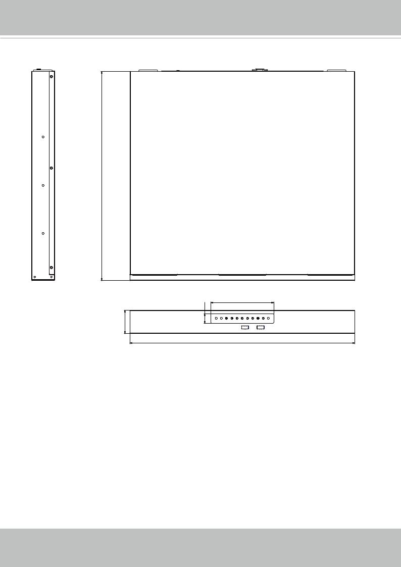
Chassis Dimensions
400
120
18
44.5 |
430
8 - User's Manual
VIVOTEK - Built with Reliability
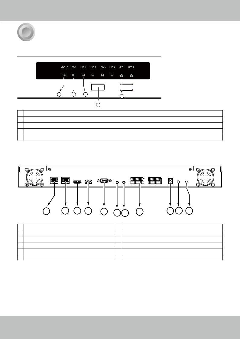
1 Physical Description
 Front View
1 |
2 |
3 |
5 |
|
|
|
4
1System status LED
2Recording activity LED
3HDD activity LED (#1 ~ 4)
4USB 2.0 ports
5Network status/activity LED
 Rear View
1 |
2 |
3 |
4 |
5 |
6 7 |
8 |
9 10 11 |
1 |
Net 1 RJ45 port - GbE uplink |
7 |
Audio IN |
2 |
Net 2 RJ45 port - GbE uplink |
8 |
DI/DO terminal block |
3 |
HDMI |
9 |
Power socket (DC56V, 2.5A) |
4 |
USB 3.0 port |
10 |
Power button |
5 |
VGA |
11 |
Reset button |
6 |
Audio OUT |
|
|
User's Manual - 9
VIVOTEK - Built with Reliability
NOTE:
You can also use the Reset button to restore system defaults. Press and hold down the button for longer than 5 seconds. The system should start restoring defaults.
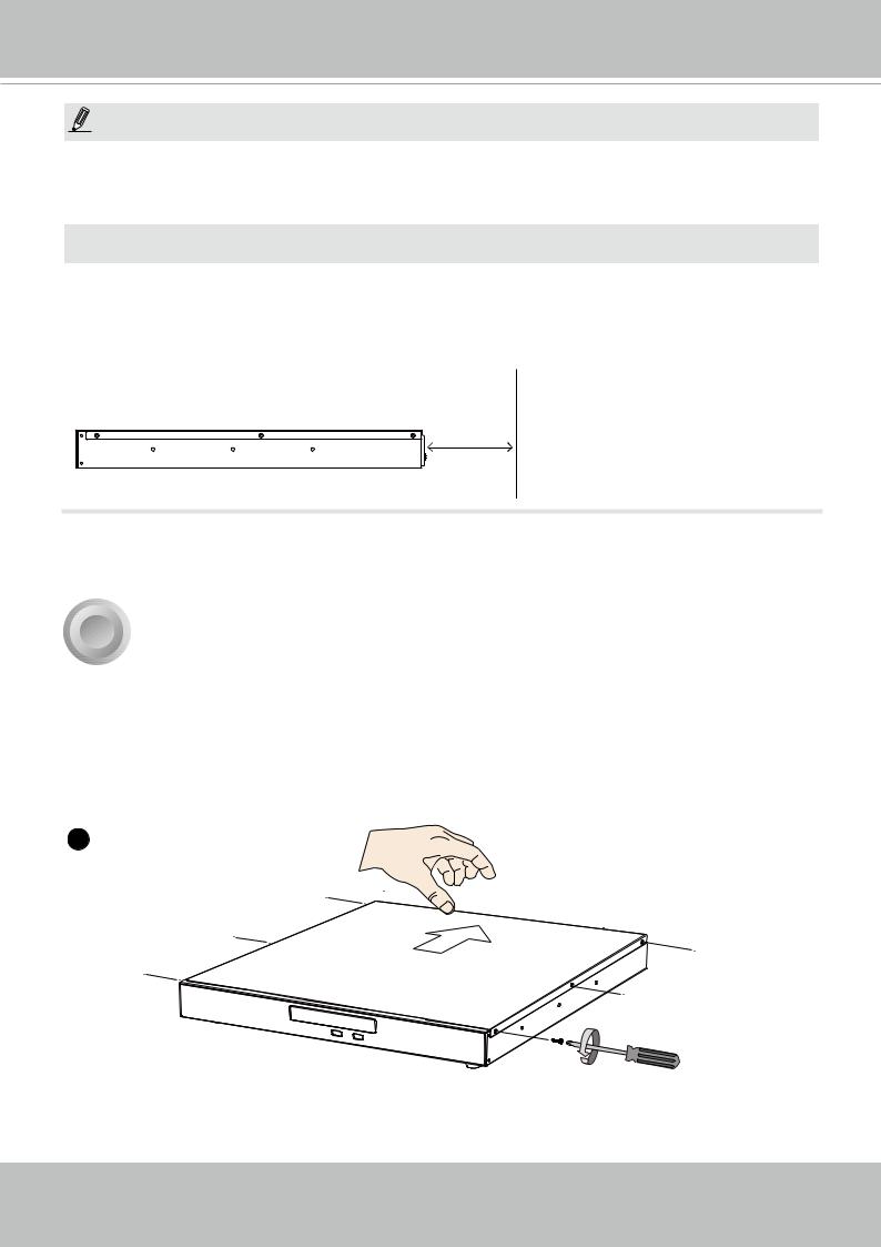
 IMPORTANT:
It is important to leave a clearance of 25cm behind the chassis. The clearance is required to ensure an adequate airflow through the chassis to ventilate heat.
To ensure normal operation, maintain ambient airflow. Do not block the airflow around chassis such as placing the system in a closed cabinet.
25cm
2 Hardware Installation
SATA hard disk(s) are user-supplied. The network video recorder can readily accommodate most of the off-the-shelf SATA hard drives.
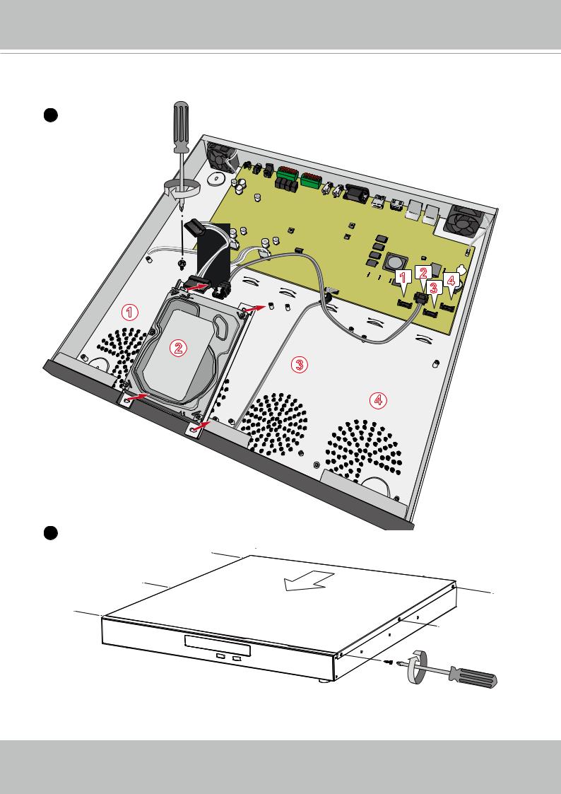
1. Use a screwdriver to loosen the retention screw on the sides of the chassis. Slide the top cover back, and then remove the top cover.
1
10 - User's Manual

VIVOTEK - Built with Reliability
2. Secure the HDD brackets to the hard drives.
2
Label side
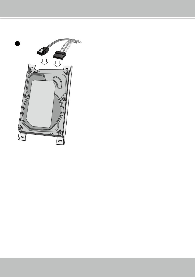
3. Connect SATA data cables to the connectors on the main board.
3
SATA Power
2 |
4 |
3 |
 1
1 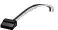
SATA Data
2
3 |
HDD connectors |
|
4


 HDD positions
User's Manual - 11
VIVOTEK - Built with Reliability
4. Connect SATA data and power cables to the hard drives.
SATA Data SATA Power
4
12 - User's Manual
VIVOTEK - Built with Reliability
5.Secure the hard disks to the mounting positions in the chassis with its label side facing up, and the connectors facing the inside of the chassis.
5


 1 2
1 2
 3
3


 4
4


2 


 3
3
4
6
User's Manual - 13
VIVOTEK - Built with Reliability
Rack-mounting (Optional, and the slide rails are separately purchased)
 IMPORTANT:
If you have either a round-holed or square-holed rack, install cage nuts or clip nuts to the desired positions on the rack posts. 

The instructions below are based on the installation to a 4-post equipment rack.
The slide rails apply to rack cabinet of a depth of 700 to 900mm. With 4 hard drives, the chassis can weigh up to 7kg.
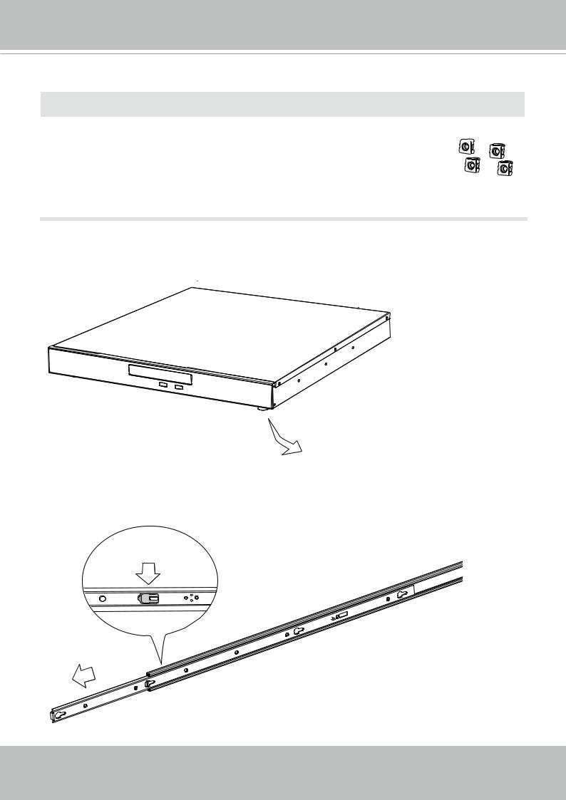
If you need to install the NVR system into a rack cabinet, 1. Remove the foot pads from underneath the chassis.
 x4
x4
2.Unpack the rack-mount rails' package, and detach the inner rails from the rail assembly. Detach the inner rail by pressing on the release tab.
Release tab
 Inner rail
14 - User's Manual
VIVOTEK - Built with Reliability
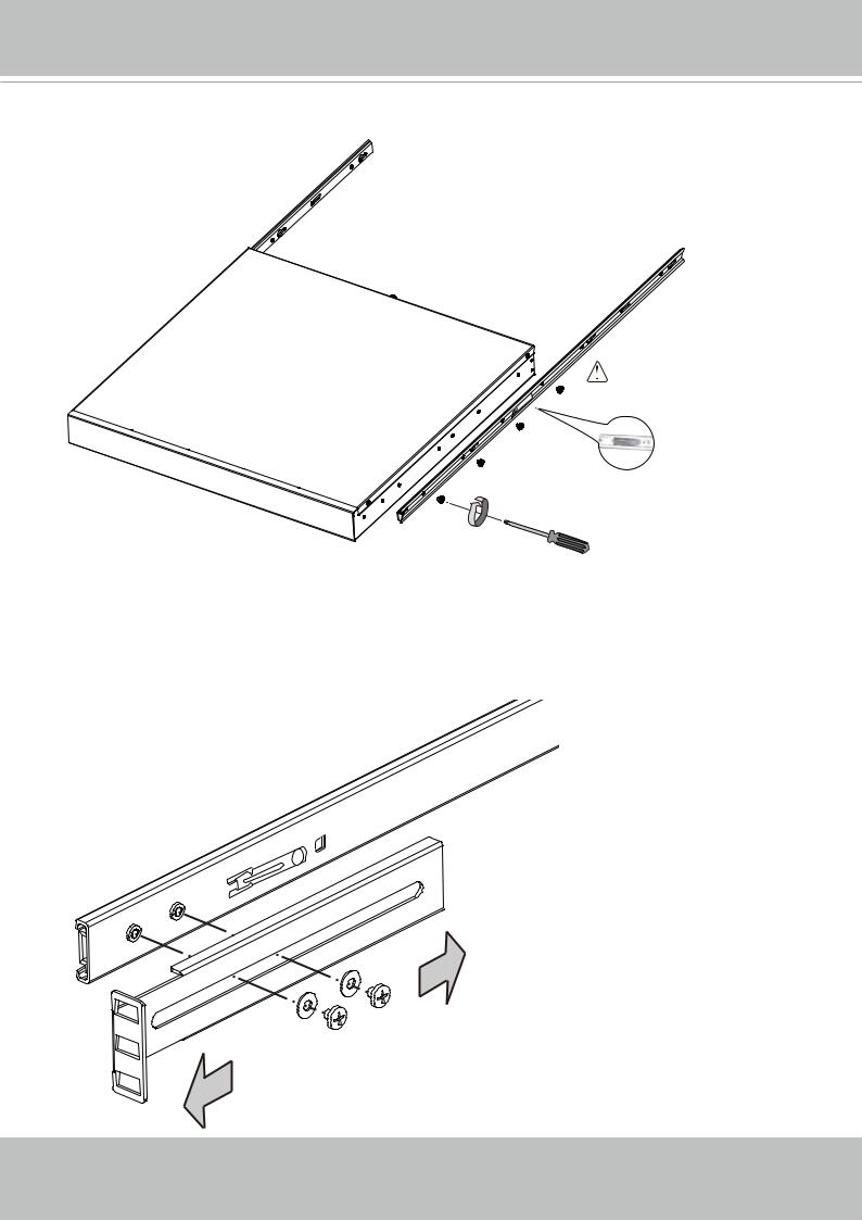
3. Secure the inner rails to the sides of the chassis using the M4 screws.
Locking Clip to the rear
M4 x6
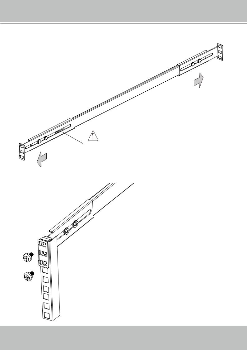
4.Secure the L-shape brackets to the frontand rear-ends of outer rails using the black round head screws and washers. Do not completely tighten the screws yet. Adjust the length of slide rails by extending and matching the rails between rack posts.
M4 screws
User's Manual - 15
VIVOTEK - Built with Reliability
Adjust the length of rails to match the rack posts.
 The side w/ a locking clip to the front
5. Secure the slide rails to rack posts using the #10 screws.
16 - User's Manual
VIVOTEK - Built with Reliability
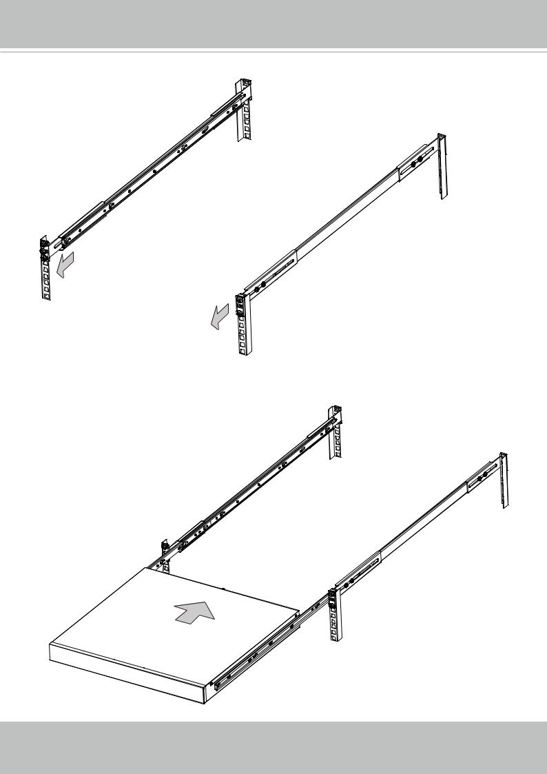
6. Pull the middle rails out of the slide rail assemblies.
7.Hold the chassis using both hands on the sides of the chassis. Align the tips of inner rails on the chassis with the open portion of the slide rail assemblies. Push the system into the assemblies until the system stops.
User's Manual - 17
VIVOTEK - Built with Reliability
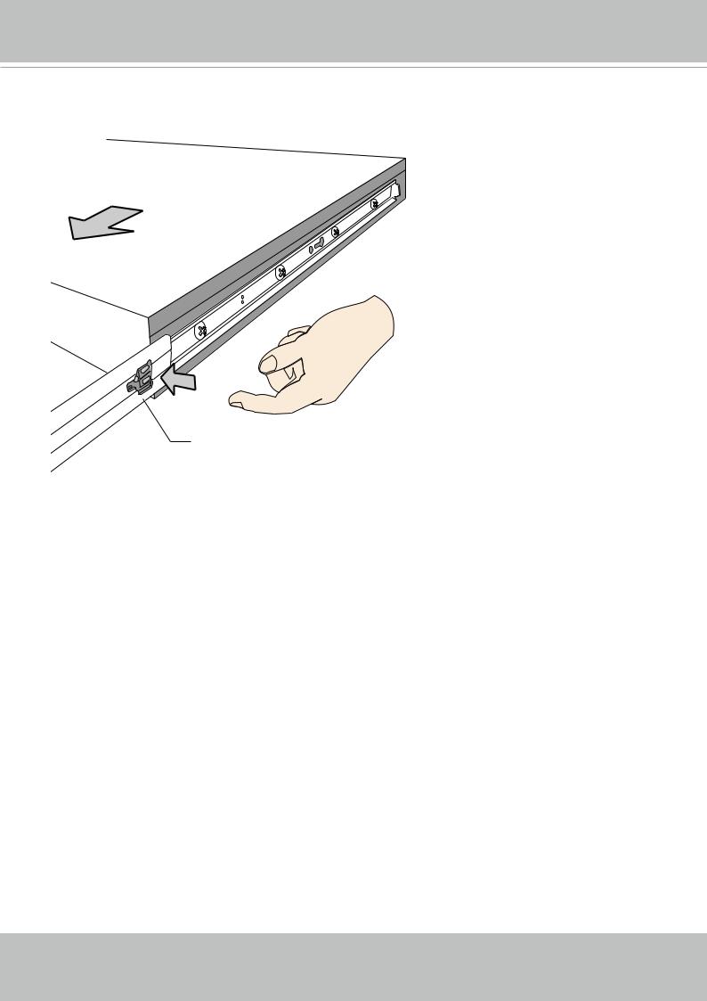
8.The inner rails and the rail assemblies should be locked on the way into the rack cabinet.
Press the release tabs on the sides to slide the chassis into rack.
 Release tab
18 - User's Manual
VIVOTEK - Built with Reliability
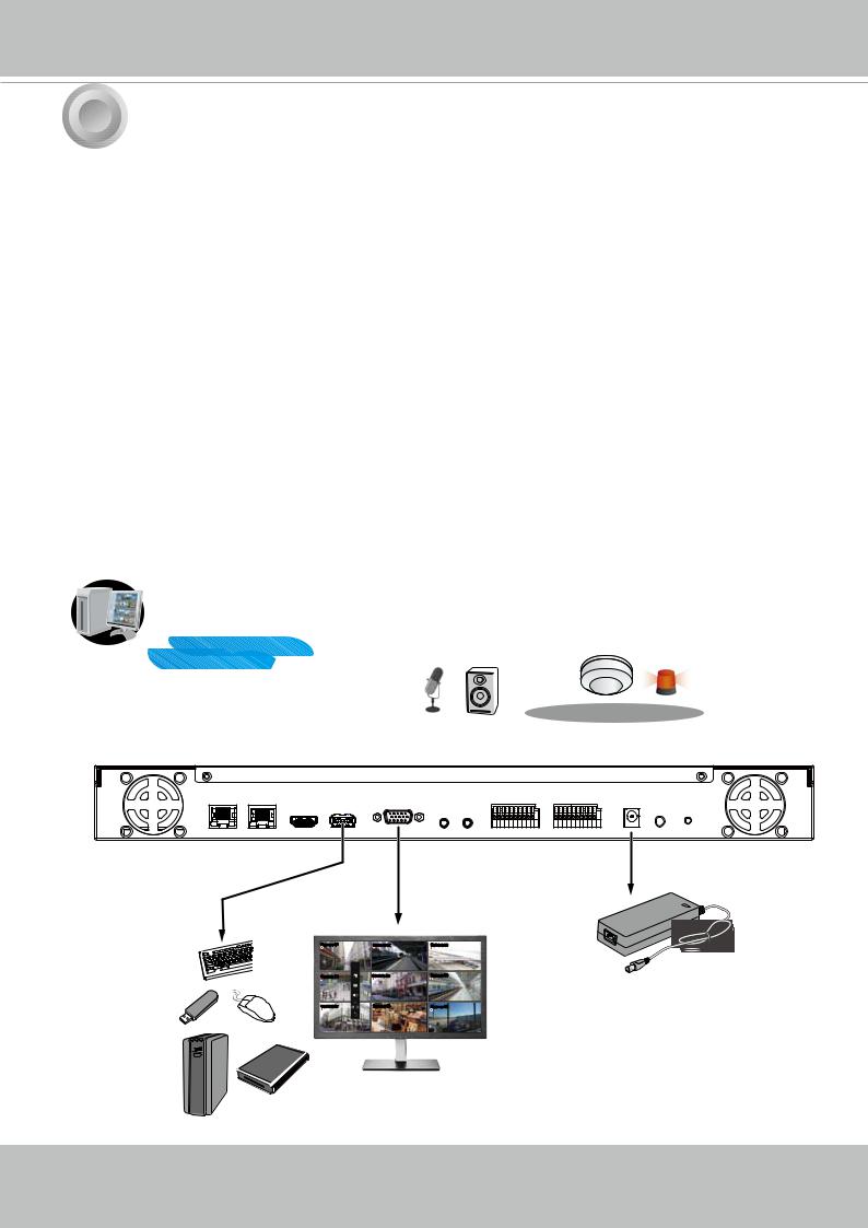
3 |
Interface Connections |
1.Connect to a monitor using an HDMI cable. VGA is also supported.
2.Connect CAT5e or better-quality Ethernet cable to the Gb/E Ethernet ports. IP cameras are connected via an Ethernet switch or PoE switches.
3.Connect USB devices such as, mouse, keyboard, USB optical drive, or USB thumb drive (formatted in FAT format), or UPS.
4.Connect external devices, such as sensors, relays, or alarms to the terminal block.
5.Connect the power adaptor to the power mains and the system.
LAN/WAN
USB 3.0
Camera 01 |
Camera 02 |
Camera 03 |
Camera 04 |
Camera 05 |
Camera 06 |
Camera 07 |
Camera 08 |
Camera 09 |
AC100~240V 50/60Hz, 2-1A
User's Manual - 19

VIVOTEK - Built with Reliability
 NOTE:
NOTE:
Although the system supports MAC Binding, the system should be able to detect VIVOTEK's cameras within the network regardless of the presence of a DHCP server. Ideally, cameras and the NVR should reside in the same subnet. If a camera's IP is changed for some reasons, the system should be able to detect its new IP.
20 - User's Manual
VIVOTEK - Built with Reliability
Terminal Block Connections
The terminal block pinouts is shown as follows:
The DO pins default status is set to Normally Closed. Connect your relay or external devices’ signal wires to the system, the system will automatically detect the current signal status. You can then trigger the external devices using the DI/DO panel on the live view.
You can also configure the system alarm setting for the system to automatically trigger a DO on the occurrence of system events. See Alarm settings on page 75.
Normally Closed 
COMMON
Normally Open
|
|
|
|
|
|
|
|
|
|
|
Alarm IN |
|
|
|
|
|
|
|
Alarm OUT |
|
|
|
|
|
|
|
|
|
|
|
|
|
|
|
|||||||||||||||||||||||||||||||||||||||||||||||
|
|
|
|
|
|
|
|
|
|
|
|
|
|
1 |
|
|
|
|
2 |
|
|
|
3 |
|
|
|
|
|
|
|
4 |
|
|
RS485 |
|||||||||||||||||||||||||||||||||||||||||||||||
|
|
|
|
|
|
|
|
|
|
|
|
|
|
|
|
|
|
|
|
|
|
|
|
|
|
|
|
|
|
|
|
|
|
|
|
|
|
|
|
|
|
|
|
|
|
|
|
|
|
|
|
|
|
|
|
|
|
|
|
||||||||||||||||||||||
|
|
1 2 3 4 5 6 7 8 G G NO |
|
|
|
|
|
COM NO COM + - |
|||||||||||||||||||||||||||||||||||||||||||||||||||||||||||||||||||||||||
|
|
|
COM NO COMNO |
||||||||||||||||||||||||||||||||||||||||||||||||||||||||||||||||||||||||||||||
|
|
|
|
|
|
|
|
|
|
|
|
|
|
|
|
|
|
|
|
|
|
|
|
|
|
|
|
|
|
|
|
|
|
|
|
|
|
|
|
|
|
|
|
|
|
|
|
|
|
|
|
|
|
|
|
|
|
|
|
|
|
|
|
|
|
|
|
|
|
|
|
|
|
|
|
|
|
|
|
|
|
|
|
|
|
|
|
|
|
|
|
|
|
|
|
|
|
|
|
|
|
|
|
|
|
|
|
|
|
|
|
|
|
|
|
|
|
|
|
|
|
|
|
|
|
|
|
|
|
|
|
|
|
|
|
|
|
|
|
|
|
|
|
|
|
|
|
|
|
|
|
|
|
|
|
|
|
|
|
|
|
|
|
|
|
|
|
|
|
|
|
|
|
|
|
|
|
|
|
|
|
|
|
|
|
|
|
|
|
|
|
|
|
|
|
|
|
|
|
|
|
|
|
|
|
|
|
|
|
|
|
|
|
|
|
|
|
|
|
|
|
|
|
|
|
|
|
|
|
|
|
|
|
|
|
|
|
|
|
|
|
|
|
|
|
|
|
|
|
|
|
|
|
|
|
|
|
|
|
|
|
|
|
|
|
|
|
|
|
|
|
|
|
|
|
|
|
|
|
|
|
|
|
|
|
|
|
|
|
|
|
|
|
|
|
|
|
|
|
|
|
|
|
|
|
|
|
|
|
|
|
|
|
|
|
|
|
|
|
|
|
|
|
|
|
|
|
|
|
|
|
|
|
|
|
|
|
|
|
|
|
|
|
|
|
|
|
|
|
|
|
|
|
|
|
|
|
|
|
|
|
|
|
|
|
|
|
|
|
|
|
|
|
|
|
|
|
|
|
|
|
|
|
|
|
|
|
|
|
|
|
|
|
|
|
|
|
|
|
|
|
|
|
|
|
|
|
|
|
|
|
|
|
|
|
|
|
|
|
|
|
|
|
|
|
|
|
|
|
|
|
|
|
|
|
|
|
|
|
|
|
|
|
|
|
|
|
|
|
|
|
|
|
|
|
|
|
|
|
|
|
|
|
|
|
|
|
|
|
|
|
|
|
|
|
|
|
|
|
|
|
|
|
|
|
|
|
|
|
|
|
|
|
|
|
|
|
|
|
|
|
|
|
|
|
|
|
|
|
|
|
|
|
|
|
|
|
|
|
|
|
|
|
|
|
|
|
|
|
|
|
|
|
|
|
|
|
|
|
|
|
|
|
|
|
|
|
|
|
|
|
|
|
|
|
|
|
|
|
|
|
|
|
|
|
|
|
|
|
|
|
|
|
|
|
|
|
|
|
|
|
|
|
|
|
|
|
|
|
|
|
|
|
|
|
|
|
|
|
|
|
|
|
|
|
|
|
|
|
|
|
|
|
|
|
|
|
|
|
|
|
|
|
|
|
|
|
|
|
|
|
|
|
|
|
|
|
|
|
|
|
|
|
|
|
|
|
|
|
|
|
|
|
|
|
NO = Normally Open
COM = Common pin
The pins are listed and described from left to right as shown in the drawing above.
Pin |
Description |
NOTE |
DI no. 1 ~ 8 Open-short-to-GND |
|
|
GPins #1~4 share a common ground. Pins #5~8 share a common ground.
NO |
Normally open. Use the DO trigger |
|
|
buttons on the live view window to |
|
|
trigger the digital output. |
|
COM |
Common pin |
|
RS485+ |
RS485 Data+ |
A 120Ω terminator is enabled on the |
RS485- |
RS485 Data- |
bus. The terminator cannot be disabled. |
User's Manual - 21

VIVOTEK - Built with Reliability
 WARNING:
If you connect the NVR to a PoE port of the AW-FED series PoE switch, make sure you turn off the PoE output on that specific port using the onboard DIP switch. Otherwise, the high power output can damage the LAN port on NVR.
PoE cameras
AW-FED PoE switch
1 2 3 4 5 6 7 8
ON
PoE ON/OFF switch
NVR
22 - User's Manual
VIVOTEK - Built with Reliability
4 Initial Configuration - via a Local Console
A local console requires the following:
1.A monitor is connected via an HDMI or VGA cable.
2.A mouse and/or a keyboard are connected to the system.
3.It is presumed that the system has not been configured yet.
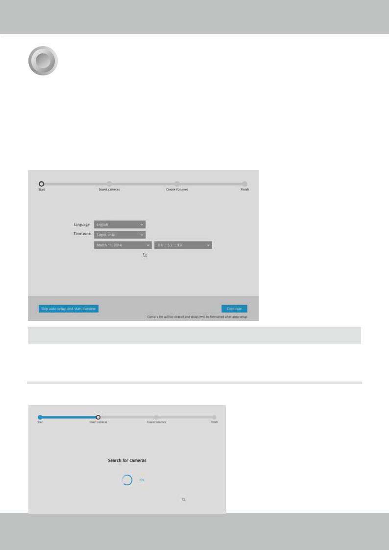
Follow the onscreen messages to complete the initial configuration:
1.Select the UI language, Time zone, and current date and time. Click on the Continue button to proceed.
 IMPORTANT:
Except in the initial setup, changing system time can produce disruptions to the existing recordings. Turning the current system time back to a time when video recording was taking place can generate duplicate files. And those files may not be playable.
2. The system will then start to scan the local subnet for connected cameras.
User's Manual - 23
VIVOTEK - Built with Reliability
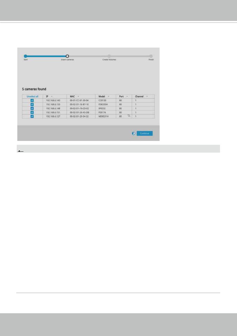
3.All cameras detected on the network will be automatically selected. If necessary, deselect the cameras you want to exclude from the configuration. Click Continue to proceed.
 NOTE:
NOTE:
1.The maximum recording bandwidth is
2560x1920 @ 120 fps (4-CH)
1920x1080 @ 480 fps (16-CH)
1280x720 @ 960 fps (32-CH)
Display bandwidth:
2560x1920 @ 30 fps (1-CH)
1920x1080 @ 120 fps (4-CH)
1280x720 @ 240 fps (8-CH)
1280x720 @ 480 fps (16-CH)
720x480 @ 960 fps (32-CH)
When cameras are recruited into the configuration, their stream 1 is used as the recording stream.
The resolution and fps (frame rate per second) of stream 1 may vary depending on the specifications of different cameras.
2.If there are more than 16 or 32 cameras in your local network, you will need to manually select cameras.
If there are less than 8 or 16 cameras, the Auto Setup will automatically move to the next configuration step.
24 - User's Manual

VIVOTEK - Built with Reliability
4.The system will automatically create volumes from the installed disk drives. The process will take several minutes.
5.An optional utility, EZConnect, is available through the Apple and Android App Stores. The EZConnect works with a server hosted by VIVOTEK for bridging and tunneling video requests between client devices and network cameras/CMS/NVR. The utility simplifies and facilitates network configuration for access across the Internet.
The prerequisites for using the EZConnect are as follows:
1.Download and install the EZConnect utility to your cell phone.
2.Both the NVR and your cell phone have access to the Internet.
With this utility, you do not need to configure IP port forwarding on router or set up a DDNS address for the NVR. You do not even need to know the IP address of the NVR. The EZConnect utility automatically manages the network parameters required for making the connection. The EZConnect comes with viewing and playback interfaces very similar to those in the iViewer utility.
To connect the NVR from a cell phone using the EZConnect: 5-1. Click on the EZConnect button on the wizard.
User's Manual - 25

VIVOTEK - Built with Reliability
5-2. The QR code will be generated.
5-3. Open the utility from your cell phone. If you already registered an account, tap LOG IN.
If not, tap SIGN UP to register an account from a VIVOTEK server.
User
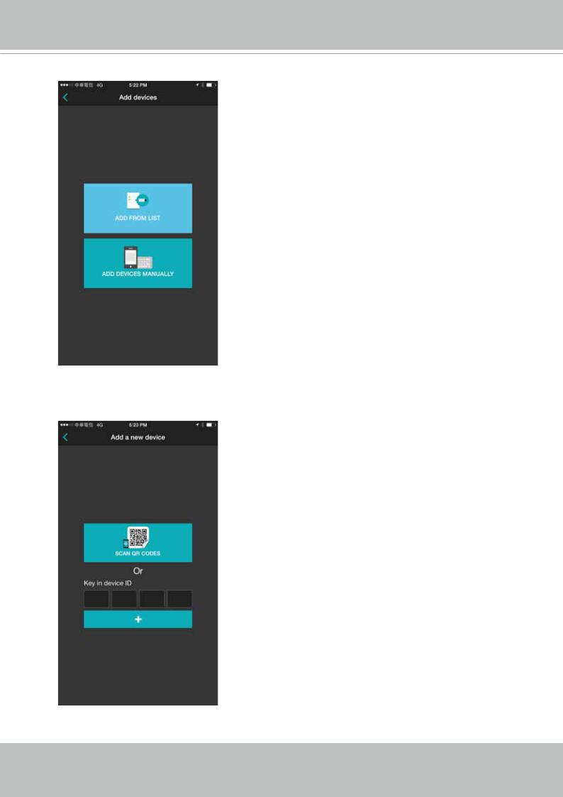
5-4. You can be defaulted to the Live view page. Tap the Add button below to add devices.
26 - User's Manual
VIVOTEK - Built with Reliability
5-5. Tap the ADD DEVICES MANUALLY button.
5-6. You can then point your cell phone lens at the NVR screen (Step 5-3.) and use the SCAN QR CODES function to establish the connection. You may also manually enter the device ID.
User's Manual - 27
VIVOTEK - Built with Reliability
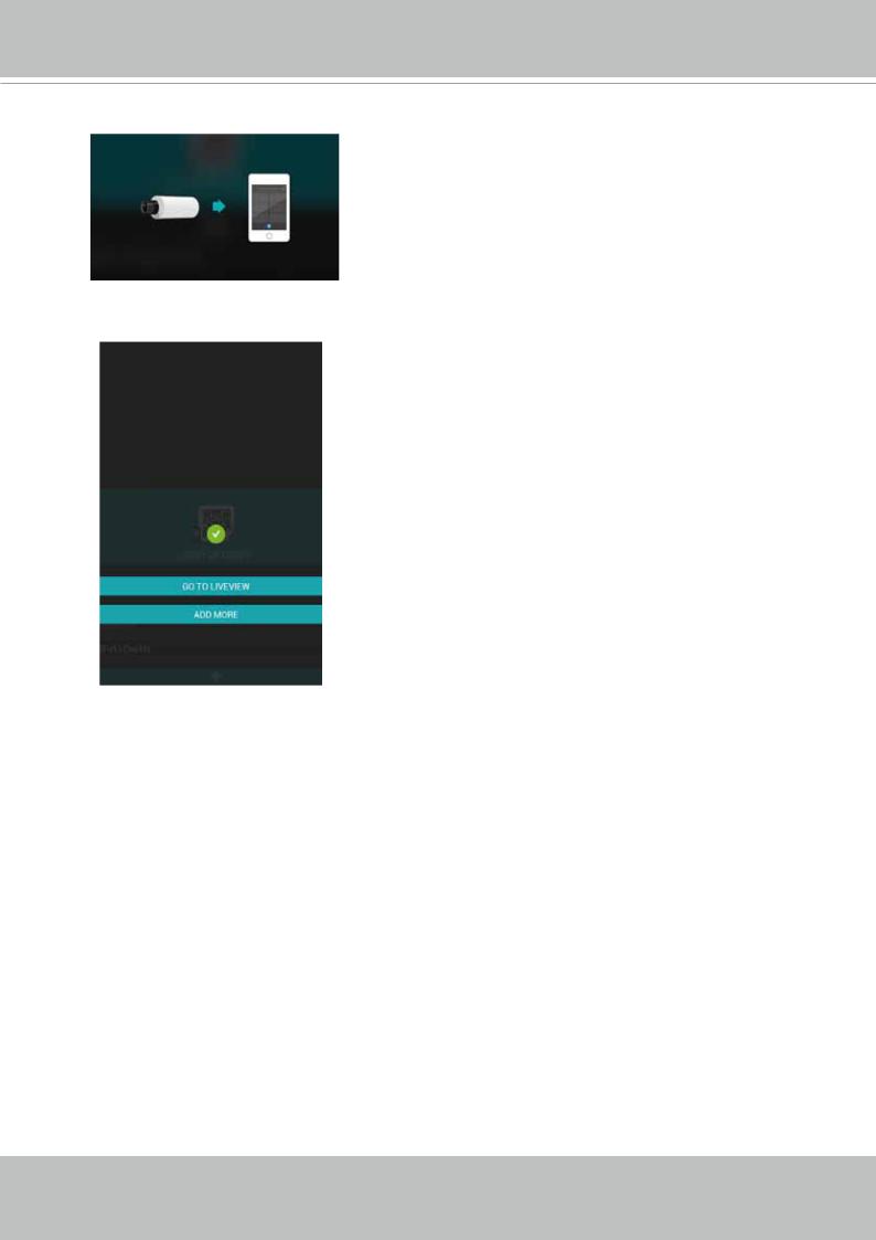
5-7. The process will take several seconds to complete.
5-8. The NVR and the cameras under it will be ready for access.
6.Click the Done button. The LiveClient screen will display, and, by default, the recording from the selected cameras will immediately take place.
28 - User's Manual
VIVOTEK - Built with Reliability
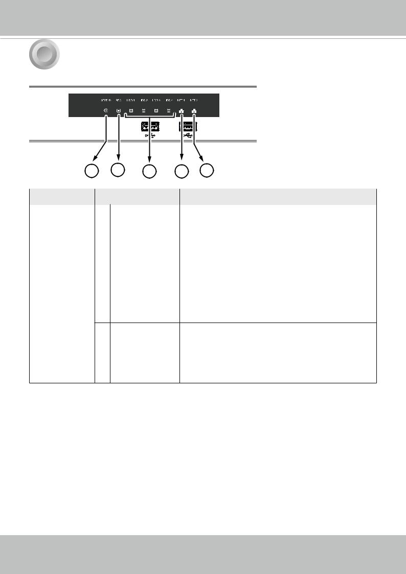
5 LED Indicators
1 |
2 |
3 |
4 |
5 |
Name |
Behavior |
Definitions |
|
|
|
|
|
1. Status LED |
1 |
Constant Green |
System is ready. |
|
2 |
Blinking Green |
Updating firmware or device pack. |
|
|
every 1 second |
|
|
3 |
Constant Red |
S.M.A.R.T.-related disk errors, or a configured H.D.D. |
|
|
|
is missing, or H.D.D. is full. Buzzer will also be |
|
|
|
sounded. When buzzer is turned off, LED will return |
|
|
|
normal. |
2. Record LED |
1 |
Flashing Red |
Camera streams are recorded to the system storage. |
|
2 |
OFF |
No recording. |
3. HDD activity |
1 |
Constant Green |
H.D.D. is connected and ready. |
LED |
2 |
Constant Red |
SMART-related disk errors or a configured H.D.D. is |
|
|
|
missing. |
3Blinking Red every H.D.D. configuration errors. 1 second
|
4 |
OFF |
H.D.D. is disconnected or removed. |
4 & 5. NET |
1 |
Flashing Orange |
Indicating on-going traffic over the LAN connection. |
activity LED |
2 |
Solid Orange |
Ethernet is connected. |
|
3 |
OFF |
Ethernet is disconnected. |
User's Manual - 29
VIVOTEK - Built with Reliability
6 Power Up and Power Down
To power up and power down,
On the initial configuration:
1.Connect the power adapter between the system and power outlet.
2.Turn on the system by pressing the power button for more than one second.
After the initial connection,
1.Press the power button for 1 second to power on.
2.Press the power button for 4 seconds to power down. The system should start flushing the cached contents in system memory and gracefully shut down.
Press the Reset button for longer than 5 seconds can restore system defaults.
 WARNING:
1.No storage system is completely fail-safe. Damage to data might occur due to file system corruption, operating system malfunction, virus infection, HDD component failures, and so on.
Therefore, it is highly recommended to regularly back up your data, and VIVOTEK disclaims responsibilities of data loss or recovery.
2.Always power off the system using the power button. Do not disconnect the power cord while the system is still operating. Doing so will result in data inconsistencies. The normal power-off procedure allows cached data to be written to disks.
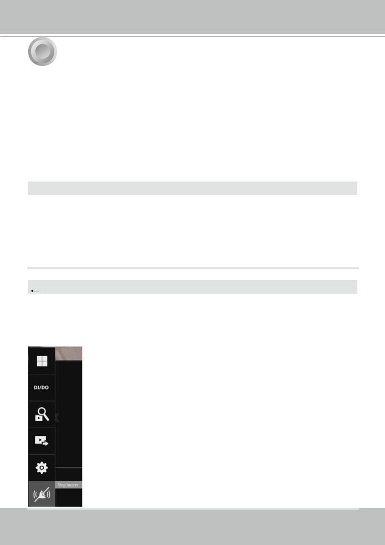
 NOTE:
NOTE:
If system buzzer is sounded, move your mouse cursor to reveal the main screen portal, and then click on the Stop buzzer button.
Serious system faults, such as a missing volume, can trigger the system buzzer. Verify the cause of system fault and turn off the buzzer.
30 - User's Manual
 Loading...