


AE Series
Outdoor Housing
Installation Guide
Ordering part no.:
AE-238 |
900041100G |
|
AE-239 |
900041200G |
|
AE-243 |
900041900G |
|
AE-244 |
900042400G |
|
AE-23A |
900042300G |
|
AE-23B |
900042200G |
Rev. 1.0 |
AE-23C |
900041700G |
|
AE-23D |
900041800G |
|
AE-23E |
900041600G |
|
AE-23F |
900042100G |
|
IP Sur veillance
UNPACKING:
Unpack carefully. Electronic components can be damaged if improperly handled or dropped. If an item appears damaged in shipment, place it properly in its carton and notify the shipper.
IMPORTANT!:
1.Read and follow Instructions: All operating and user instructions should be read and followed before the unit is to be operated.
2.Electrical Connections: Only a qualified electrician is allowed to make electrical connections.
I |
Specifications |
|
|
|
|
|
|
|
|
|
|
Model Number |
AE-238, AE-243 |
AE-23A, AE-23B, AE- |
AE-239, AE-244 |
AE-23E, AE-23F |
|
|
|
|
23C, AE-23D |
|
|
Power Input |
24V AC/ DC |
24V AC/ DC |
PoE: 50~57V DC |
PoE: 30/60/95W, 50~57V |
|
|
|
|
|
|
DC |
Max. Output power |
30W |
80W, 100W (-AIW) |
30W |
25W - 30W PoE PSE |
|
budget |
|
|
|
|
48W - 60W PoE PSE |
|
|
|
|
|
72W - 95W PoE PSE |
Power Consumption |
Window heater: 10W; |
Window heater: 10W; |
Window heater: 10W; |
Window heater: 10W; |
|
|
|
Blower: 2W; Camera: 6 ~ |
Blower: 2W; Camera: 6 |
Blower: 2W; Camera: 6 ~ |
Blower: 2W; Camera: 6 ~ |
|
|
8W |
~ 8W; Cold start heater: |
8W; IR: 6W |
8W; Wiper: 6W |
|
|
|
30W |
|
|
|
|
|
|
|
|
Environmental |
-20°C ~ +65°C (-4°F ~ |
-20°C ~ +65°C |
-20°C ~ +65°C |
-20°C ~ +65°C |
|
Operation Temp. |
+149°F) |
-20°C ~ +50°C (w/ IR) |
-20°C ~ +50°C (w/ IR) |
-20°C ~ +50°C (w/ IR) |
|
|
|
|
-24°C ~ +50°C (Cold start) |
|
|
|
|
|
|
|
|
Window heater ON/OFF |
≤ 30°C (86°F) ON; ≥ 35°C |
≤ 30°C (86°F) ON; ≥ 35°C |
≤ 30°C (86°F) ON; ≥ 35°C |
≤ 30°C (86°F) ON; ≥ 35°C |
|
|
|
(95°F) OFF |
(95°F) OFF |
(95°F) OFF |
(95°F) OFF |
|
|
|
|
|
|
Blower Control |
≥40°C (104°F) ON; ≤ 35°C |
≥40°C (104°F) ON; ≤ 35°C |
≥40°C (104°F) ON; ≤ 35°C |
≥40°C (104°F) ON; ≤ 35°C |
|
|
|
(95°F) OFF |
(95°F) OFF |
(95°F) OFF |
(95°F) OFF |
Protection Level |
IP67, IK10 |
IP67, IK10 (IP66 w/ wiper) |
IP67, IK10 |
IP67, IK10 (IP66 w/ wiper) |
|
|
|
|
|
|
|
Construction |
Die-cast Aluminum Alloy |
Die-cast Aluminum Alloy |
Die-cast Aluminum Alloy |
Die-cast Aluminum Alloy |
|
|
|
|
|
|
|
Coating |
|
White epoxy powder |
White epoxy powder |
White epoxy powder |
White epoxy powder |
|
|
coating |
coating |
coating |
coating |
|
|
|
|
|
|
Dimensions |
415 (L) x 170 (W) x 125 (H) |
502.8 (L) x 170 (W) x |
415 (L) x 170 (W) x 125 (H) |
502.8 (L) x 170 (W) x 135.5 |
|
|
|
mm |
135.5 (H) mm |
mm - IR not included |
(H) mm - IR not included |
Net Weight |
2,2kg (4.84 lb) |
2,7kg (5.95 lb), 2,8kg (6.18 |
2,2kg (4.85 lb) |
2,7kg (5.95 lb), 2,8kg (6.18 |
|
|
|
|
lb - wiper model) |
|
lb - wiper model) |
If you plan to install this camera enclosure into a tropical, sea coastal, or an environment where salt water or corrosive industrial waste water/moist are present, please seal each stainless steel screws and fittings with a silicon grease compounds. This will help prevent electrolysis to occur and extend the life span of the camera and housing.
IMPORTANT:
1.Disconnect devices: A readily accessible disconnect device in the building installation wiring should be incorporated.
2.Electrical Connection: Only a qualified electrician is allowed to make electrical connections.
2
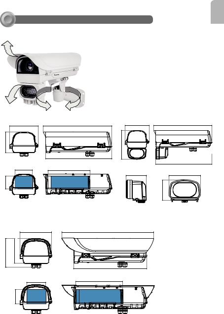
II Mounting Configuration & Dimensions
Swivel Positions and Directions
English
AE-238, AE-239
170 mm
125 mm
|
105 mm |
|
mm |
USABLE |
|
77.4 |
||
AREA |
||
|
AE-243, AE-244
415 mm |
170 mm |
415 mm |
|
206.9 mm |
|
400 mm |
|
|
255 mm |
|
400 mm |
|
|
|
|
87.01 mm |
135 mm |
USABLE AREA |
|
|
|
|
88.05 mm |
AE-23A, 23B, 23C, 23D, 23E, 23F
|
|
170 mm |
158.5 mm |
135.5 mm |
|
|
|
105 mm |
|
mm |
USABLE |
|
77.4 |
|
|
AREA |
|
|
|
502.8 mm
400 mm
255 mm
USABLE AREA |
3
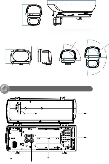
Dimensions with the IR unit and wiper
217.4 mm
135 mm |
|
87.01 mm |
|
|
|
88.05 mm
502.8 mm
417 mm
R9 |
6 |
. 5 |
95˚ |
45 |
95˚ |
R9 |
. |
||
|
|
|
6 |
|
|
|
|
95˚ |
|
III Component Description
Ventilation fan |
Window frame |
|
heater coil |
||
|
|
VAIR module |
AC/DC or PoE Power |
Camera Mounting Platform |
distribution board |
|
M16 1/2" Waterproof cable glands |
|
4
IV Installation Suggestions
 WARNING:
•When install a housing with an IR illuminator:
Please avoid eye exposure or apply appropriate protection, such as wearing a pair of Infrared protection glasses, when working with the product. Always use camera live view to oberve IR lighting effects.
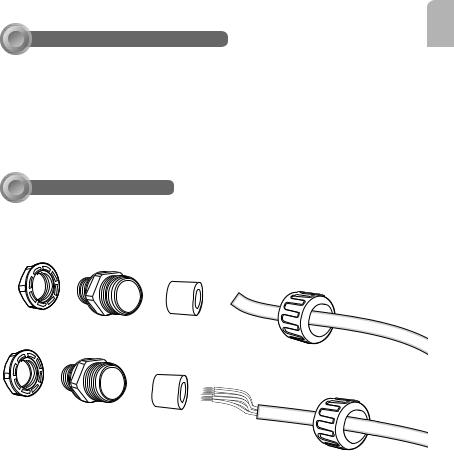
VInstallation
1.Prepare power wires, a ground wire, and a CAT5e Ethernet cable. Pass them through the M16 waterproof connectors and its waterproof components.
English
Ethernet cable Ø4 ~ 6.5mm
Power wires & DI/DO wires,
a combo cable from IR illuminator (if applied)
Note that some cables are connected when shipped. You do not need to connect heater, blower, and the front IR powere wires.
5
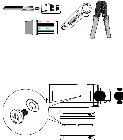
You may need to remove the RJ45 connector, and use a crimping tool to connect the
Ethernet wires to an RJ45 connector inside the enclosure. Use an Ethernet cable of the width of 5 ~ 6.5mm.
o: white/orange stripe O: orange solid
g: white/green stripe
B: blue solid
b: white/blue stripe
G: green solid
br: white/brown stripe BR: brown solid
o |
1 |
O |
2 |
g |
3 |
B |
4 |
b |
5 |
G |
6 |
br |
7 |
BR |
8 |
2. When done, tighten up and install the waterproof connectors.
3. Assemble the camera components, e.g., the CS ring and lens module. Secure the mounting plate to the bottom of the camera (the label side) using the included screw.
6

4. Adjust the camera's position so that the lens module can flush align with the tempered glass. Secure the camera using the screws and washers to the bottom of the housing.
English
Lens flush w/ edge of enclosure
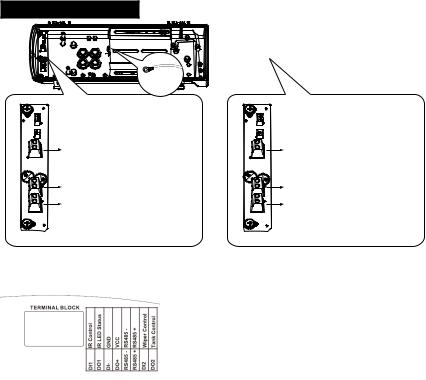
5. Connect 24V power source to the power input terminal. Connect power wires from the DC 12V output to the camera. You may also connect the 24V power to drive an external
IRs.
Below is the distribution board drawing power from 24V AC/DC.
AE-23A, AE-23B, AE-23C, AE-23D
I/O terminal block
24V AC/DC OUT |
|
Heater |
|
Power LED |
Blower |
|
|
24V AC/DC IN |
12V DC OUT |
|
|
Camera heater |
IR angle selector |
|
|
|
|
|
Connectors to the front IR |
|
|
7 |
AE-238, AE-243
Ground |
|
AE-238 |
AE-243 |
DC 12V OUT - to camera |
for IR LED |
AC 24V OUT - to external IR |
AC 24V OUT - to camera |
AC 24V IN |
AC 24V IN |
Below is the pinouts for the DI/DO terminal block:
Facing the rear side of the housing, from left to right:
DO2 |
Tank water pump control, connects to IP camera's DO for manually triggering |
|
washer. |
DI2 |
Wiper control. |
RS485+ |
RS485+, RS485 can be used to control IR illuminator beam angles, etc. |
RS485- |
RS485- |
DO+ |
+5V VCC |
DI- |
GND |
DO1 |
IR LED status |
DI1 |
IR control, synchronizes day/night mode switching for IP camera. It is related to IR |
|
cut filter. |
8
 Loading...