


AE-211/AE-232/AE-233
Camera Enclosure
User’s Manual
Rev. 1.0
IP Surveillance

CAUTION:
TO REDUCE RISK OF FIRE OR ELECTRIC SHOCK, DO NOT REMOVE COVER. NO USER SERVICEABLE PARTS INSIDE.
REFER SERVICING TO QUALIFIED SERVICE PERSONNEL.
UNPACKING:
Unpack carefully. Electronic components can be damaged if improperly handled or dropped. If an item appears damaged in shipment, place it properly in its carton and notify the shipper.
IMPORTANT!
1.Read and follow Instructions: All operating and user instructions should be read and followed before the unit is to be operated.
2.Electrical Connections: Only a qualified electrician is allowed to make electrical connections.
I Specifications
Model Number |
AE-211/AE-232/AE-233 |
Power Input |
90~240VAC (+/-10%) |
Rating Current |
3.5 A |
Heater Control |
18 +/-3°C (ON) / 28 +/-3°C (OFF) |
Blower Control |
35 +/-3°C (ON) / 25 +/-3°C (OFF) |
Environmental Operation Temp. |
-20°C ~ +50°C |
Protection Level |
IP68 |
Temper Glass thickness |
4mm |
Mounting Bracket |
Fully-cable Management |
Construction |
Die-cast Aluminum Alloy |
Coating |
Ivory Powder & Stove Finish |
Dimensions |
425 (L) x 160 (W) x 165 (H) mm |
Camera Space |
275 (L) x 90 (W) x 100 (H) mm |
Net Weight |
5230 g |
2
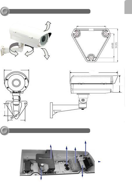
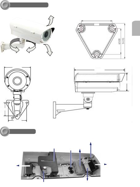
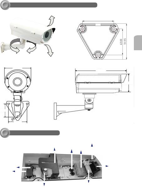
II Mounting Configuration & Dimensions
Swivel Positions and |
Bracket Base Dimensions |
Directions |
82.80mm |
|
|
|
|
|
69.00mm |
||||
|
94.95mm |
BR-13 Full-cable Management
Bracket
160mm
425mm
165mm
68.5mm
83.2mm
English
III Component Description
Ground Wire
Camera Mounting Cable Conduits
Platform Bushing Power Supply
Unit
Heater
Shield 
 Blower
Heater 
Terminal Block
Thermal Control Assembly
Board
3
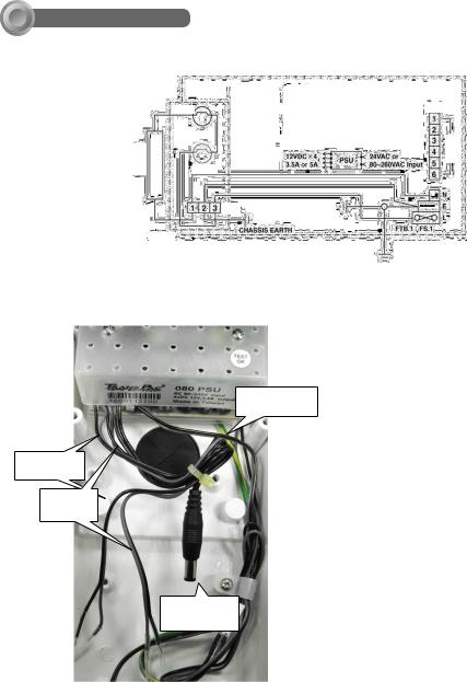
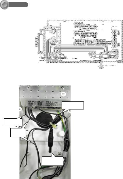
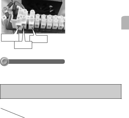
IV Wiring Diagram
Shown below is the wiring diagram for the window demister. A spare 6-way terminal block is provided at the rear of the chassis for additional camera and lens connections.
TB.1 |
6 way terminal block |
TB.2 |
3 way terminal block |
FTB.1 |
Fused terminal block |
STAT.1 |
18°C Thermostat |
STAT.2 |
35°C Thermostat |
H.1 |
Heater |
PSU |
Power Supply Unit |
P.C.B.1 |
Thermal control |
|
circuit board |
FS.1 |
3 Amp. Fuse |
STAT.1
H.1 or
B.2
STAT.2
PCB.1
DC Output of PSU Connectors
H1., Heaterr |
|
|
STAT.1 TURN OFF at 28O |
||
. |
|
°C |
TURN ON at 18°C |
O |
TB. 1 |
TURN ON at 18 C |
||
B2. Blower |
|
|
STATB2, Blower.2 TURN OFF at 25°C
TURNSTAT.2ONTURNat 35°COFF at 25O C
TURN ON at 35O C
12VDC X4 |
|
|
|
24VAC or |
|
PSU |
|
||
3.5A or 5A |
|
|
80~260VAC Input |
|
|
|
|
||
|
|
|
|
|
TB.2
|
CHASSISEARTH |
|
FTB. 1 FS. 1 |
|
|
|
|
|
|
|
|
|
|
|
|
|
|
|
|
|
|
COVEREARTH |
|
SPARE
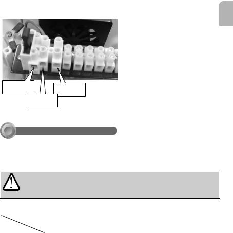
1.Pins 1, 2, 3, and 4 are DC 12V output for motor lens, siren, or speaker connecitons. If they are not connected, remove cables from the connectors.
2.Pins 5 and 6 are DC 12V output for camera.
Lines for heater & blower
Pins 1 & 2
12V Output
Pins 3 & 4
12V Output
Pins 5 & 6
DC for camera
4
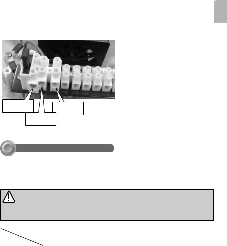
AC Power Connection
Below are AC power connections to the FTB. 1 connector.
AC 24V Input |
AC 24V Input |
|
Ground
Green Line
English
V Installation Suggestions
If you plan to install this camera enclosure into a tropical, sea coastal, or an environment where salt water or corrosive industrial waste water/moist are present, please seal each stainless steel screws and fittings with a silicon grease compounds. This will help prevent electrolysis to occur and extend the life span of the camera and housing.
IMPORTANT!
1.Disconnect devices: A readily accessible disconnect device in the building installation wiring should be incorporated.
2.Electrical Connection: Only a qualified electrician is allowed to make electrical connections.
Features |
Heater: |
Blower |
PSU |
|
|
On at 18O C |
On at 35O C |
(Power Supply Unit) |
|
Model Name |
Off at 28O C |
Off at 25O C |
|
|
|
12VDC/24VAC |
12VDC |
080 |
324 |
080/F |
- |
• |
• |
- |
|
|
|
||
|
|
|
|
|
080/HF |
• |
• |
• |
- |
|
|
|
||
|
|
|
|
|
324/HF |
• |
• |
- |
• |
|
|
|
||
|
|
|
|
|
1.080: [90~240VAC input (+/-10%), 4x12VDC output, 3.5A]
2.324 (24VAC input, 4x12VDC output, 3.5A)
5
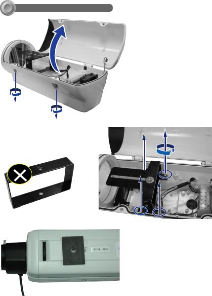
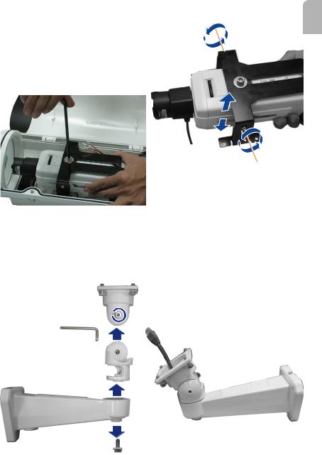
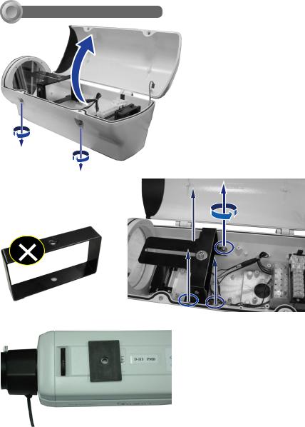
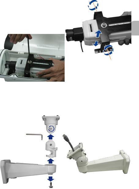
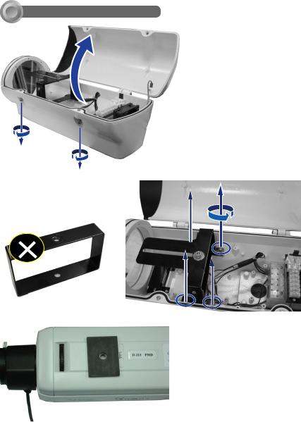
VI Camera Installation
2. Remove the camera bracket by loosening 4 screws using a mid-size
Phillips screwdriver. Loosen the socket screw on top of the bracket to remove the rectangular support.
Rectangular Support
1. Loosen the socket screws using the included L-type hex key wrench, and open the cover.
3. Place the rubber insulation pad on top of the camera with its opening aligned with the screw hole.
6
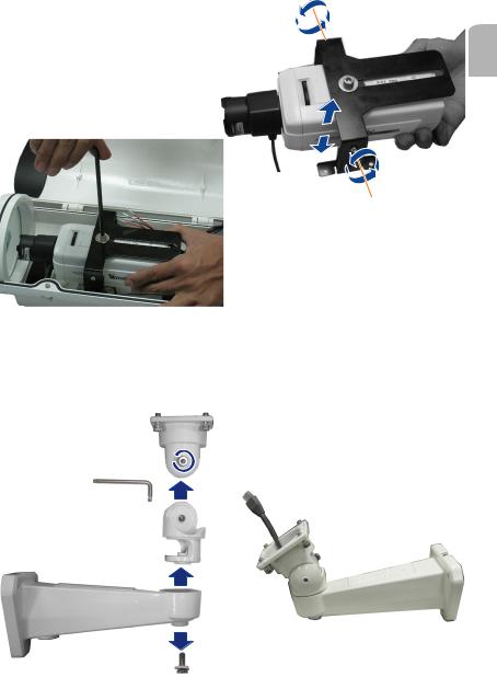
4. Mount the bracket on top of camera in a reversed orientation to gain more space for the lens module to zoom in/ out. You may change the camera's vertical position by adjusting the screws on the sides of bracket.
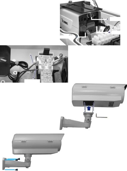
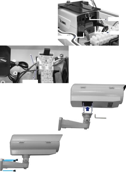
6. Route your AC input, DI/DO, and Ethernet cables through the BR-13 bracket, and then the rubber bushing at the bottom of the housing.
English
5. When done, place the camera into the housing, secure the bracket to the bottom of housing, and tighten the socket screw.
In order to pass cables through, you may need to disassemble the BR-13 bracket. Use the included L-type wrench to loosen the screws and pass cables through the bracket.
When done, re-assemble the bracket and its swivel parts.
7
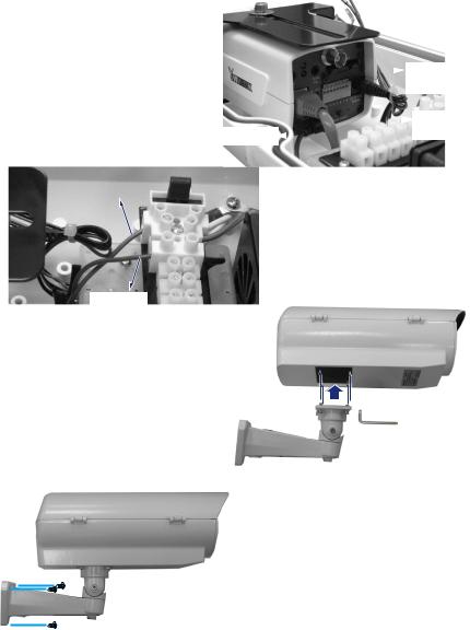
7. Connect the Ethernet cable and the
12V DC connector to your camera. You may use the BNC connector for initial image adjustment.
RJ-RJ45-45Ethernett 


 BNCConnector
Connector

 12VACDCInput
Input
|
8. Connect 24V AC lines to the FTB. |
ACInput |
|
|
1 connectors. |
|
ACACInput
9. Secure the housing to the bracket using the supplied socket screws. Pan and tilt the housing to aim at the monitored area.
10. Mount the bracket to a desired position using the included mounting screws.
8

11. After you adjust the camera's zoom and focus, close and secure the cover by tightening the socket screws using the L-type wrench.
English
9

I
|
AE-211/AE-232/AE-233 |
|
90~240VAC (+/-10%) |
|
|
|
3.5 A |
|
|
|
18 +/-3°C ( ) / 28 +/-3°C ( ) |
|
35 +/-3°C ( ) / 25 +/-3°C ( ) |
|
-20°C ~ +50°C |
|
IP68 |
|
|
|
4mm |
|
|
|
|
|
|
|
|
|
|
|
|
|
|
|
425 (L) x 160 (W) x 165 (H) mm |
|
|
|
275 (L) x 90 (W) x 100 (H) mm |
|
|
|
5230 g |
|
|
10
II
|
|
82.80mm
( )
|
|
|
|
|
69.00mm |
||||
|
94.95mm |
BR-13
160mm
425mm
165mm
68.5mm
83.2mm
III

|
|
|
|
|
|
|
|
||
|
|
|
|


11
IV
6
TB.1 |
6 |
|
|
|
|
|
|
|
|
|
|
|
|
|
|
|
|
|
|
|
|
|
|
|
|
|
|
|
. |
|
|
|
|
|
|
|
|||
|
|
|
|
|
|
|
|
|
|
|
|
|
|
|
|
||||
TB.2 |
3 |
|
|
|
|
|
|
|
|
|
H1, Heater |
|
|
|
|
|
|
|
|
|
|
|
|
|
|
|
|
|
AT. 28°C |
|
O |
|
|
|
|||||
FTB.1 |
|
|
|
|
|
|
|
|
|
|
ST .1 TURN OFF at 28 C |
|
|
|
|||||
|
|
|
|
|
|
|
|
|
18°C |
|
O |
|
|
|
|
TB. 1 |
|||
STAT.1 |
18°C |
|
|
STAT.1 |
|
|
|
|
|
|
TURN ON at 18 C |
|
|
|
|
||||
|
|
|
|
|
|
|
|
|
B2. |
|
|
|
|
|
|
|
|||
|
|
|
|
|
|
|
|
|
|
|
|
|
|
|
|||||
STAT.2 |
35°C |
|
|
|
|
|
|
|
|
|
B2, Blower |
|
|
|
|
|
|
|
|
|
|
|
|
|
|
|
|
|
|
|
STAT.2 25°C |
|
|
|
|
|
|
||
|
|
|
|
|
|
|
|
|
|
|
STAT°.2 TURN OFF at 25 C |
|
|
|
|||||
H.1 |
|
|
|
|
|
|
|
|
|
|
35 C |
|
|
O |
|
|
|
||
|
|
|
|
|
|
|
|
|
TURN ON at 35O C |
|
|
|
|
|
|||||
PSU |
|
H.1 |
|
|
|
|
|
|
|
|
|
|
|
|
|
|
|
|
|
|
|
|
|
|
|
|
|
|
|
|
|
|
|
|
|
|
|||
1 |
|
or |
|
|
|
|
|
|
|
|
12VDC X4 |
|
|
|
|
24VAC or |
|
||
|
|
|
|
|
|
|
|
PSU |
|
|
|
||||||||
FS.1 |
3 |
B.2 |
|
|
|
|
|
|
|
|
3.5A or 5A |
|
|
|
80~260VAC Input |
|
|||
|
|
|
STAT.2 |
|
|
|
|
|
|
|
|
|
|||||||
|
|
|
|
|
|
|
|
|
|
|
|
|
|
|
|
|
|||
|
|
|
|
|
|
|
|
|
|
|
|
|
|
|
|||||
|
|
|
|
|
|
|
|
|
|
|
|
|
|
|
|
|
|
|
|
|
|
|
|
|
|
|
|
|
|
|
|
|
|
|
|
|
|||
|
|
|
|
|
|
|
|
TB.2 |
|
|
|
|
|
|
|
|
|
||
|
|
|
|
|
|
|
|
|
CHASSIS EARTH |
|
|
|
|
FTB. 1 FS. 1 |
|||||
PCB.1
COVER EARTH
DC
SPARE
1.1 2 3 4 DC 12V
2.5 6 DC 12V
1 2 12V
3 4 12V
5 6DC
12
AC
FTB.1 AC
AC 24V |
AC 24V |
|
( )
V
/
|
|
|
|
(PSU) |
||
|
|
18°C |
35°C |
|
|
|
|
|
28°C |
25°C |
|
|
|
|
|
12VDC/24VAC |
12VDC |
080 |
324 |
|
080/F |
|
- |
• |
• |
|
- |
|
|
|
|
|
||
|
|
|
|
|
|
|
080/HF |
|
• |
• |
• |
|
- |
|
|
|
|
|
||
|
|
|
|
|
|
|
324/HF |
|
• |
• |
- |
|
• |
|
|
|
|
|
||
|
|
|
|
|
|
|
1.080 [90~240VAC (+/-10%) 4x12VDC 3.5A]
2.324 (24VAC 4x12VDC 3.5A)
13
VI
1. L
2.
3.
14
4. /
( )
5.
6. AC DI/DOBR-13
15
BR-13L
7. 12V DCBNC
|
|
|
|
|
|
|
|
|
|
|
|
onnector |
|
|
|
|
|
|
|
|
|
|
|
|
BNC |
|
|
|
|
|
|
|
|
|
|
|
|
|
|
|
|
|
|
|
|
|
|
|
|
|
|
|
|
|
|
|
|
|
|
|
|
|
|
|
|
|
|
12VACDCInput |
|
|
|
|
|
|
|
|
|
|
|
|
|||
|
|
|
|
|
|
|
|
|
|
||||
|
|
|
RJ-45 Ethernet |
|
|
|
|
|
|
|
|
|
|
|
|
|
RJ-45 |
|
|
||||||||
|
|
|
8. 24V AC FTB. 1 |
|
|||||||||
AC Input |
|
|
|
||||||||||
AC Input
9.
10.
16

11. L
( )
17

员来操作。
I
|
AE-211/AE-232/AE-233 |
|
90~240V (+/-10%) |
|
3.5 A |
|
18 +/-3°C ( ) / 28 +/-3°C ( ) |
|
35 +/-3°C ( ) / 25 +/-3°C ( ) |
|
-20°C ~ +50°C |
|
IP68 |
|
4mm |
|
|
|
|
|
|
|
|
|
& |
|
425 (L) x 160 (W) x 165 (H) mm |
|
275 (L) x 90 (W) x 100 (H) mm |
|
5230 g |
18
II &
|
|
|
82.80mm |
( )
|
|
|
|
|
69.00mm |
||||
|
94.95mm |
BR-13
160mm
425mm
165mm
68.5mm
83.2mm
III


|
|
|
|
|
|
|
|
||
|
|
|
|


19

IV
6
TB. 1 |
6- |
|
|
|
|
|
|
|
|
|
|
|
|
|
|
|
|
|
|
|
|
|
|
|
|
|
|
|
|
|
|
|
|
H1. |
|
|
|
|
|
|
|
|
|
||||
|
|
|
|
|
|
|
|
|
|
|
|
|
|
|
|
|
|
|
|||||
TB. 2 |
3- |
|
|
|
|
|
|
|
|
|
|
|
, Heater |
|
|
O |
|
|
|
|
|
||
|
|
|
|
|
|
|
|
|
|
STAT.1 28°C |
|
|
|
|
|
||||||||
FTB. 1 |
|
|
|
|
|
|
|
|
|
|
|
|
. TURN OFF at 28 C |
|
|
|
|
|
|||||
|
|
|
|
|
|
|
|
|
|
18°C |
O |
|
|
|
|
|
TB. 1 |
||||||
|
|
STAT.1 |
|
|
|
|
|
|
|
|
|
|
|
||||||||||
STAT.1 |
18°C |
|
|
|
|
|
|
|
|
|
|
TURN ON at 18 C |
|
|
|
|
|
||||||
|
|
|
|
|
|
|
|
|
|
B2. |
|
|
|
|
|
|
|
|
|
||||
|
|
|
|
|
|
|
|
|
|
|
|
|
|
|
|
|
|
||||||
STAT.2 |
35°C |
|
|
|
|
|
|
|
|
|
|
STATB2, Blower.2 25°C |
|
|
|
|
|
|
|
||||
|
|
|
|
|
|
|
|
|
|
STAT35°.C2 TURN OFF at 25O C |
|
|
|
|
|
||||||||
H.1 |
|
|
|
|
|
|
|
|
|
|
|
|
TURN ON at 35O C |
|
|
|
|
|
|
|
|||
PSU |
|
H.1 |
|
|
|
|
|
|
|
|
|
|
|
|
|
|
|
|
|
|
|
|
|
|
|
|
|
|
|
|
|
|
|
|
|
|
|
|
|
|
|
|
|
|
|||
P.C.B. 1 |
|
or |
|
|
|
|
|
|
|
|
|
12VDC X4 |
|
|
|
|
24VAC or |
|
|
||||
|
|
|
|
|
|
|
|
|
PSU |
|
|
|
|
||||||||||
FS. 1 |
3 |
B.2 |
|
|
|
|
|
|
|
|
|
3.5A or 5A |
|
|
|
80~260VAC Input |
|
|
|||||
|
|
|
STAT.2 |
|
|
|
|
|
|
|
|
|
|
|
|||||||||
|
|
|
|
|
|
|
|
|
|
|
|
|
|
|
|
|
|
|
|
|
|||
|
|
|
|
|
|
|
|
|
|
|
|
|
|
|
|
|
|
|
|||||
|
|
|
|
|
|
|
|
|
|
|
|
|
|
|
|
|
|
|
|
|
|
|
|
|
|
|
|
|
|
|
|
|
|
|
|
|
|
|
|
|
|
|
|||||
|
|
|
|
|
|
|
|
TB.2 |
|
|
|
|
|
|
|
|
|
|
|
||||
|
|
|
|
|
|
|
|
|
|
|
|
|
|
|
|
|
|
|
|
|
|
|
|
|
|
|
|
|
|
|
|
|
|
|
|
|
|
|
|
|
|
|
|
FTB. 1 FS. 1 |
|
||
|
|
|
PCB.1 |
|
|
|
|
|
CHASSIS EARTH |
|
|
|
|
|
|||||||||
|
|
|
|
|
|
|
|
|
|
|
|
|
|
|
|
|
|
|
|
|
|
||
COVER EARTH
SPARE
1.1, 2, 3 4 12V
2.5 6 12V
1 2 12V
3 4 12V
5 6
20
FTB.1
( )
24V |
24V |
|
|
||
|
||
|
||
|
|
V
/
|
|
|
|
PSU |
|
|
|
|
18°C |
35°C |
( ) |
|
|
|
|
28°C |
25°C |
|
|
|
|
|
|
|
|
|
|
|
|
12VDC/24VAC |
12VDC |
080 |
324 |
|
080/F |
|
- |
• |
• |
|
- |
|
|
|
|
|
||
|
|
|
|
|
|
|
080/HF |
|
• |
• |
• |
|
- |
|
|
|
|
|
||
|
|
|
|
|
|
|
324/HF |
|
• |
• |
- |
|
• |
|
|
|
|
|
||
|
|
|
|
|
|
|
1.080: [ 90-240V (+/-10%), 4x12V , 3.5A]
2.324 ( 24V 4x12V 3.5A)
21

VI
1. L
2. Phillips 4
3.
22
4.
( )
5.
6. DI/DOBR-13
BR-13L
23
7. 12VBNC
|
|
|
|
|
|
|
|
|
|
|
BNCConnector |
|
|
|
|
|
|
|
|
|
|||||
|
|
|
|
|
|
|
|
|
|
|||
|
|
|
|
|
|
|
|
|
|
|
|
|
|
|
|
|
|
|
|
|
|
|
|
|
|
|
|
|
|
|
|
|
|
|
|
|
|
|
|
|
|
|
|
|
|
|
|
|
|
12V |
|
|
|
|
|
|
|
|
|
|
|
|
AC Input |
|
|
|
RRJ-4-45 Ethernet |
|
|
|
|
|
|
|
|
|
|
|
|
|
|
|
|
|
|
|
||||
|
|
|
|
|
|
|
||||||
|
|
|
|
|
|
|||||||
|
|
8. |
24V FTB.1 |
|
||||||||
|
|
|
||||||||||
AC Input |
|
|
|
|
|
|
|
|
|
|
||
AC Input
9.
10.
24

11. L
( )
25

発火や感電の危険を避けるため、カバーは開かないでください。ユーザによって交換できる部 品はありません。
開封は慎重に行います。不適切な取り扱いや落下は、電機部品に損傷を与える可能性があ ります。運送の際に損傷したとみられる部分がある場合、カートンに収めてから運送業者にご 連絡ください。

1.
.
I
|
AE-211/AE-232/AE-233 |
|
90~240VAC(±10%) |
|
3.5A |
|
18±3 ( )/28±3 ( ) |
|
35±3 ( )/25±3 ( ) |
|
-20 ~+50 |
|
IP68 |
|
4mm |
|
|
|
|
|
|
|
|
|
|
|
|
|
425 (L) x 160 (W) x 165 (H) mm |
|
275 (L) x 90 (W) x 100 (H) mm |
|
5230 g |
26
II
|
|
|
82.80mm |
|
|
|
|
|
69.00mm |
|
|||
|
94.95mm |
|
||
|
|
|
|
BR-13
160mm
425mm
165mm
68.5mm
83.2mm
III
|
|
|
|
|
|
|
|
|
||||
|
|
|
|
|
|
|
|
|
||||
|
|
|
|
|
|
|
|
|
|
|||
|
|
|
|
|
|
|
|
|
||||
|
|
|
|
|
|
|
|
|||||
|
|
|
|
|
|
|||||||
|
|
|
|
|
|
|||||||
|
|
|
|
|
|
|||||||
|
|
|
|
|
|
|
|
|
|
|
||
|
|
|
|
|
|
|
|
|
|
|||
|
|
|
|
|
|
|
|
|
|
|
||
|
|
|
|
|
|
|
|
|
|
|
||
|
|
|
|
|
|
|
|
|
|
|
||
|
|
|
|
|
|
|
|
|||||
|
|
|
|
|
|
|
|
|
|
|
||
|
|
|
|
|
|
|
|
|||||
|
|
|
|
|
|
|
||||||
|
|
|
|
|
|
|
||||||
27

IV
6
TB.1 |
6 |
|
|
|
|
|
|
|
|
|
|
|
|
|
|
|
|
|
|
|
|
||
|
|
|
|
|
|
|
|
H1. |
|
|
|
|
|
|
|
|
|
||||||
|
|
|
|
|
|
|
|
|
|
|
|
|
|
|
|
|
|||||||
TB.2 |
3 |
|
|
|
|
|
|
|
|
|
, Heater |
|
|
O |
|
|
|
|
|
||||
|
|
|
|
|
|
|
|
STAT.1 28°C |
|
|
|
|
|
|
|||||||||
FTB.1 |
|
|
|
|
|
|
|
|
|
|
. TURN OFF at 28 C |
|
|
|
|
|
|||||||
|
|
|
|
|
|
|
|
18°C |
|
O |
|
|
|
|
|
TB. 1 |
|||||||
STAT.1 |
|
|
|
|
|
|
|
|
|
|
|
|
|||||||||||
STAT.1 |
18°C |
|
|
|
|
|
|
|
|
|
|
TURN ON at 18 C |
|
|
|
|
|
||||||
|
|
|
|
|
|
|
|
|
|
B2. |
|
|
|
|
|
|
|
|
|
||||
|
|
|
|
|
|
|
|
|
|
|
|
|
|
|
|
|
|
||||||
STAT.2 |
35°C |
|
|
|
|
|
|
|
|
|
|
STATB2, Blower.2 25°C |
|
|
|
|
|
|
|
|
|||
|
|
|
|
|
|
|
|
|
|
35STAT°C .2 TURN OFF at 25O C |
|
|
|
|
|
||||||||
H.1 |
|
|
|
|
|
|
|
|
|
|
|
|
TURN ON at 35O C |
|
|
|
|
|
|
|
|||
PSU |
|
H.1 |
|
|
|
|
|
|
|
|
|
|
|
|
|
|
|
|
|
|
|
|
|
|
|
|
|
|
|
|
|
|
|
|
|
|
|
|
|
|
|
|
|
|
|||
P.C.B. 1 |
|
or |
|
|
|
|
|
|
|
|
|
12VDC X4 |
|
|
|
|
24VAC or |
|
|
||||
|
|
|
|
|
|
|
|
|
PSU |
|
|
|
|
||||||||||
FS. 1 |
3A |
B.2 |
|
|
|
|
|
|
|
|
|
3.5A or 5A |
|
|
|
80~260VAC Input |
|
|
|||||
|
|
|
STAT.2 |
|
|
|
|
|
|
|
|
|
|
|
|||||||||
|
|
|
|
|
|
|
|
|
|
|
|
|
|
|
|
|
|
|
|
|
|||
|
|
|
|
|
|
|
|
|
|
|
|
|
|
|
|
|
|
|
|||||
|
|
|
|
|
|
|
|
|
|
|
|
|
|
|
|
|
|
|
|
|
|
|
|
|
|
|
|
|
|
|
|
|
|
|
|
|
|
|
|
|
|
|
|||||
|
|
|
|
|
|
|
|
TB.2 |
|
|
|
|
|
|
|
|
|
|
|
||||
|
|
|
|
|
|
|
|
|
|
|
|
|
|
|
|
|
|
|
|
|
|
|
|
|
|
|
|
|
|
|
|
|
|
|
|
|
|
|
|
|
|
|
|
FTB. 1 FS. 1 |
|
||
|
|
|
PCB.1 |
|
|
|
|
|
|
CHASSIS EARTH |
|
|
|
|
|
||||||||
|
|
|
|
|
|
|
|
|
|
|
|
|
|
|
|
|
|
|
|
|
|
|
|
COVER EARTH
PSU DC
SPARE
1.1, 2, 3, 4 DC 12V
2.5 6 DC 12V
1 212V
3
4 12V
5 6DC
28
AC
AC FTB.1
AC 24V |
AC 24V |
|
リード線
V
/

1.
.
|
|
|
|
PSU( ) |
||
|
|
18 |
35 |
|
|
|
|
|
28 |
25 |
|
|
|
|
|
12VDC/24VAC |
12VDC |
080 |
|
324 |
080/F |
|
- |
• |
|
• |
- |
|
|
|
|
|
||
|
|
|
|
|
|
|
080/HF |
|
• |
• |
|
• |
- |
|
|
|
|
|
||
|
|
|
|
|
|
|
324/HF |
|
• |
• |
|
- |
• |
|
|
|
|
|
||
|
|
|
|
|
|
|
1.080: [90~240VAC (±10%), 4x12VDC , 3.5A]
2.324: (24VAC , 4x12VDC , 3.5A)
29
VI
1. L
2. 4
3.
30
 Loading...