


IFP6560/IFP7560
Commercial Touch Display
User Guide
IMPORTANT: Please read this User Guide to obtain important information on installing and using your product in a safe manner, as well as registering your product for future service. Warranty information contained in this User Guide will describe your limited coverage from ViewSonic Corporation, which is also found on our web site at http:// www.viewsonic.com in English, or in specific languages using the Regional selection box in the upper right corner of our website. “Antes de operar su equipo lea cu idadosamente las instrucciones en este manual”
Model No. VS17302/ VS17303
Thank you for choosing ViewSonic
As a world leading provider of visual solutions, ViewSonic is dedicated to exceeding the world’s expectations for technological evolution, innovation, and simplicity. At ViewSonic, we believe that our products have the potential to make a positive impact in the world, and we are confident that the ViewSonic product you have chosen will serve you well.
Once again, thank you for choosing ViewSonic !

Compliance Information
NOTE: This section addresses all connected requirements and statements regarding regulations. Confirmed corresponding applications shall refer to nameplate labels and relevant markings on unit.
FCC Compliance Statement
This device complies with part 15 of FCC Rules. Operation is subject to the following two conditions: (1) this device may not cause harmful interference, and (2) this device must accept any interference received, including interference that may cause undesired operation.
This equipment has been tested and found to comply with the limits for a Class B digital device, pursuant to part 15 of the FCC Rules. These limits are designed to provide reasonable protection against harmful interference in a residential installation. This equipment generates, uses, and can radiate radio frequency
energy, and if not installed and used in accordance with the instructions, may cause harmful interference to radio communications. However, there is no guarantee that interference will not occur in a particular installation. If this equipment does cause harmful interference to radio or television reception, which can be determined
by turning the equipment off and on, the user is encouraged to try to correct the interference by one or more of the following measures:
•Reorient or relocate the receiving antenna.
•Increase the separation between the equipment and receiver.
•Connect the equipment into an outlet on a circuit different from that to which the receiver is connected.
•Consult the dealer or an experienced radio/TV technician for help.
Warning: You are cautioned that changes or modifications not expressly approved by the party responsible for compliance could void your authority to operate the equipment.
Industry Canada Statement
CAN ICES-3 (B)/NMB-3(B)
Contains FCC ID:
IC ID:
CE Conformity for European Countries
The device complies with the EMC Directive 2014/30/EU and Low Voltage
Directive 2014/35/EU.
Following information is only for EU-member states:
The mark shown to the right is in compliance with the Waste Electrical and
Electronic Equipment Directive 2012/19/EU (WEEE).The mark indicates the requirement NOT to dispose the equipment as unsorted municipal waste, but use the return and collection systems according to local law.
i

Indian Restriction of Hazardous Substances
Restriction on Hazardous Substances statement (India) This product complies with the “India E-waste Rule 2011” and prohibits use of lead, mercury, hexavalent chromium, polybrominated biphenyls or polybrominated diphenyl ethers in concentrations exceeding 0.1 weight % and 0.01 weight % for cadmium, except for the exemptions set in Schedule 2 of the Rule.
Declaration of RoHS2 Compliance
This product has been designed and manufactured in compliance with Directive
2011/65/EU of the European Parliament and the Council on restriction of the use of certain hazardous substances in electrical and electronic equipment (RoHS2
Directive) and is deemed to comply with the maximum concentration values issued by the European Technical Adaptation Committee (TAC) as shown below:
Substance |
Proposed Maximum |
Actual |
|
Concentration |
Concentration |
||
|
|||
|
|
|
|
Lead (Pb) |
0.1% |
< 0.1% |
|
|
|
|
|
Mercury (Hg) |
0.1% |
< 0.1% |
|
|
|
|
|
Cadmium (Cd) |
0.01% |
< 0.01% |
|
|
|
|
|
Hexavalent Chromium (Cr6+) |
0.1% |
< 0.1% |
|
Polybrominated biphenyls (PBB) |
0.1% |
< 0.1% |
|
|
|
|
|
Polybrominated diphenyl ethers (PBDE) |
0.1% |
< 0.1% |
|
|
|
|
|
Bis (2-ethylhexyl) phthalate (DEHP) |
0.1% |
< 0.1% |
|
|
|
|
|
Butyl benzyl phthalate (BBP) |
0.1% |
< 0.1% |
|
|
|
|
|
Dibutyl phthalate (DBP) |
0.1% |
< 0.1% |
|
|
|
|
|
Diisobutyl phthalate (DIBP ) |
0.1% |
< 0.1% |
|
|
|
|
Certain components of products as stated above are exempted under the Annex III of the RoHS2 Directives as noted below:
Examples of exempted components are:
1.Mercury in cold cathode fluorescent lamps and external electrode fluorescent lamps (CCFL and EEFL) for special purposes not exceeding (per lamp):
(1)Short length ( 500 mm): maximum 3.5 mg per lamp.
(2)Medium length ( 500 mm and 1,500 mm): maximum 5 mg per lamp.
(3)Long length ( 1,500 mm): maximum 13 mg per lamp.
2.Lead in glass of cathode ray tubes.
3.Lead in glass of fluorescent tubes not exceeding 0.2% by weight.
4.Lead as an alloying element in aluminium containing up to 0.4% lead by weight.
5.Copper alloy containing up to 4% lead by weight.
ii

6.Lead in high melting temperature type solders (i.e. lead-based alloys containing
85% by weight or more lead).
7.Electrical and electronic components containing lead in a glass or ceramic other than dielectric ceramic in capacitors, e.g. piezoelectronic devices, or in a glass or ceramic matrix compound.
Cautions and Warnings
1.Read these instructions completely before using the equipment.
2.Keep these instructions in a safe place.
3.Heed all warnings and follow all instructions.
4.Always handle the LCD display with care when moving it.
5.Never remove the rear cover. This LCD display contains high-voltage parts.
You may be seriously injured if you touch them.
6.Do not use this equipment near water. Warning: To reduce the risk of fire or electric shock, do not expose this apparatus to rain or moisture.
7.Avoid exposing the LCD display to direct sunlight or another heat source. Orient the LCD display away from direct sunlight to reduce glare.
8.Clean with a soft, dry cloth. If further cleaning is required, see the “Care and Maintenance” section in this guide for further instructions.
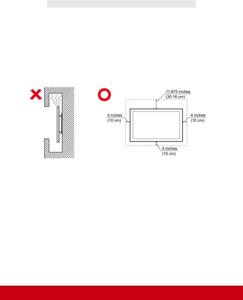
9.Do not block any ventilation openings. Install the equipment in accordance with the manufacturer’s instructions.
10.Do not install near any heat sources such as radiators, heat registers, stoves, or other devices (including amplifiers) that produce heat.
11.Place the LCD display in a well ventilated area. Do not place anything on the LCD display that prevents heat dissipation.
12.Do not place heavy objects on the LCD display, video cable, or power cord.
13.If smoke, an abnormal noise, or a strange odor is present, immediately switch the LCD display off and call your dealer or ViewSonic. It is dangerous to continue using the LCD display.
14.Do not attempt to circumvent the safety provisions of the polarized or groundingtype plug. A polarized plug has two blades with one wider than the other. A grounding type plug has two blades and a third grounding prong. The wide blade and the third prong are provided for your safety. If the plug does not fit into your outlet, consult an electrician for replacement of the outlet.
15.Protect the power cord from being tread upon or pinched, particularly at the plug, and the point where if emerges from the equipment. Be sure that the power outlet is located near the equipment so that it is easily accessible.
(Continued on next page)
iii

16.Only use attachments/accessories specified by the manufacturer.
17.Use only with the cart, stand, tripod, bracket, or table specified by the manufacturer, or sold with the equipment. When a cart is used, use caution when moving the cart/equipment combination to avoid injury from tipping over.
18.Unplug this equipment when it will be unused for long periods of time.
19.Refer all servicing to qualified service personnel. Service is required when the unit has been damaged in any way, such as: if the power-supply cord or plug is damaged, if liquid is spilled onto or objects fall into the unit, if the unit is exposed to rain or moisture, or if the unit does not operate normally or has been dropped.
20.The Unit is a Monitor with LED backlight intended for general office used.
iv

Contents |
|
|
Compliance Information |
|
|
FCC Compliance Statement................................................................ |
i |
|
Industry Canada Statement................................................................. |
i |
|
CE Conformity for European Countries............................................... |
i |
|
Indian Restriction of Hazardous Substances....................................... |
ii |
|
Declaration of RoHS2 Compliance...................................................... |
ii |
|
Cautions and Warnings....................................................................... |
iii |
|
Copyright Information |
|
|
For Your Records................................................................................ |
1 |
|
1. Getting Started |
|
|
1.1 |
Package Contents......................................................................... |
2 |
1.2 |
Wall Mount Kit Specifications (VESA)........................................... |
3 |
2. ViewBoard Features |
|
|
2.1 |
Control Panel Overview................................................................ |
5 |
2.2 |
Terminal Interface Overview......................................................... |
8 |
2.3 |
Remote Control Overview............................................................. |
9 |
2.4 |
Inserting Remote Control Batteries............................................. |
10 |
2.5 |
Remote Control Receiver Range................................................ |
11 |
3. Set Up Your Display |
|
|
3.1 |
Connecting an External Device................................................... |
12 |
3.2 |
RS232 Connections.................................................................... |
14 |
3.3 |
Connect a USB, HDMI or Media devices.................................... |
15 |
3.4 |
Video and Audio out connection................................................. |
16 |
4. ViewBoard Basic Operation |
|
|
4.1 |
ViewBoard Launcher screen....................................................... |
19 |
4.2 |
Tool Bar...................................................................................... |
21 |
4.3 |
ViewBoard OSD (On Screen Display) Menu.............................. |
24 |
5. ViewBoard Embedded Application and Setting |
|
|
5.1 vBoard......................................................................................... |
53 |
|
5.2 |
ViewBoard Cast.......................................................................... |
58 |
5.3 |
Other default apps...................................................................... |
61 |
v

6.Trouble Shooting
7.Care and Maintenance
8.Display Modes
8.1 VGA............................................................................................ |
68 |
8.2 HDMI1/2/3/OPS/SDM................................................................. |
69 |
8.3 DP............................................................................................... |
70 |
9.Specifications
10.RS-232 Protocol
10.1 |
Introduction............................................................................... |
72 |
10.2 |
Description................................................................................ |
72 |
10.3 |
Protocol..................................................................................... |
74 |
Warranty Statement |
|
|
Limited Warranty............................................................................... |
89 |
|
Mexico Limited Warranty.................................................................. |
91 |
|
vi

Copyright Information
Copyright © ViewSonic Corporation, 2018. All rights reserved.
Macbook, Macbook Pro, Mac OS, iOS are registered trademarks of Apple Inc.
Microsoft, Windows, and the Windows logo are registered trademarks of Microsoft
Corporation in the United States and other countries.
ViewSonic, the three birds logo, OnView, ViewMatch, and ViewMeter are registered trademarks of ViewSonic Corporation.
VESA is a registered trademark of the Video Electronics Standards Association. DPMS, DisplayPort, and DDC are trademarks of VESA.
Disclaimer: ViewSonic Corporation shall not be liable for technical or editorial errors or omissions contained herein; nor for incidental or consequential damages resulting from furnishing this material, or the performance or use of this product.
In the interest of continuing product improvement, ViewSonic Corporation reserves the right to change product specifications without notice. Information in this document may change without notice.
No part of this document may be copied, reproduced, or transmitted by any means, for any purpose without prior written permission from ViewSonic Corporation.
|
For Your Records |
Product Name: |
IFP6560/IFP7560 |
Model Number: |
ViewSonic Commercial Touch Display |
VS17302/VS17303 |
|
Document Number: |
IFP6560/IFP7560_UG_ENG Rev. 1A 10-30-18 |
Serial Number: |
_______________________________________ |
Purchase Date: |
_______________________________________ |
Product disposal at end of product life
ViewSonic respects the environment and is committed to working and living green. Thank you for being part of Smarter, Greener Computing.
Please visit ViewSonic website to learn more.
USA & Canada: http://www.viewsonic.com/company/green/recycle-program/ Europe: http://www.viewsoniceurope.com/eu/support/call-desk/
Taiwan: https://recycle.epa.gov.tw/
1
1. Getting Started
Congratulations on your purchase of a ViewBoard
Important! Save the original box and all packing material for future shipping needs.
Note: The word “Windows” in this user guide refers to Microsoft Windows operating system.
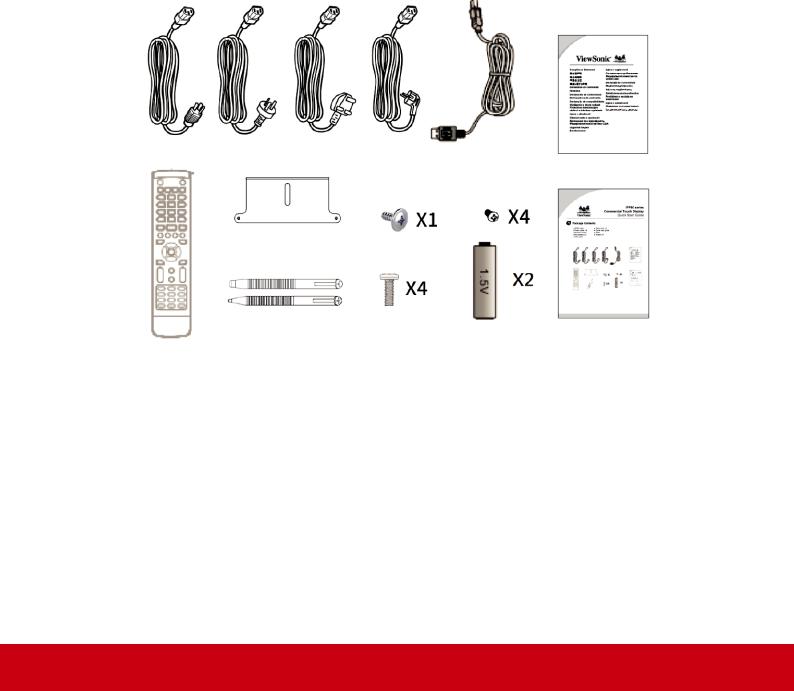
1.1 Package Contents
• |
HDMI cable |
• Stylus pen x 2 |
|
• |
Power cable x 4 |
• |
Quick start guide |
• |
Remote control |
• |
Plate |
• |
AAA battery x 2 |
• |
Screw x 9 |
• |
USB cable |
|
|
2

1.2 Wall Mount Kit Specifications (VESA)
To obtain a wall-mounting kit or height adjustment base, contact ViewSonic® or your local dealer. Refer to the instructions that come with the base mounting kit. Do the following for wall mount installation.
1.Verify that the display power was turned off, and then disconnect the power cord.
2.Remove touch pans from the front bezel of display. Lay the display face down on a towel or blanket. Making sure the surface of panel won’t be damaged when lay the display down.
3.To fix wall mount braces (or holder) on the back cover using screws of the appropriate length. (Screws removal might be required.)
4.To find and identify a VESA mount bracket which compatible with display VESA mount holder. To fix the bracket on a wall which made by cement or metal. Attach the display on the wall mount bracket and make sure it’s solid.
IFP6560
IFP7560
3
•ViewSonic provides the standard dimensions for wall mount kits as shown in the table below.
Model |
VESA Spec. |
Screw |
Quantity |
IFP6560 |
600x400mm |
M8x18mm |
4 |
IFP7560 |
800x400mm |
M8x18mm |
4 |
NOTE: For use only with UL Listed Wall Mount Bracket with minimum weight/load: 80kg
•To find the perfect mount, please browse www.viewsonic.com or call our service team.
•When purchasing our wall mount kit, a detailed install manual and all parts necessary for assembly were provided.
•Do not use the screws that longer than the standard dimension, as they may cause damage to the inside of the LCD display set.
4
2. ViewBoard Features
This section is mention about the features of interface and keypad on IFP6560 and
IFP7560.
Note: The features or applications described in this user’s manual may vary depending on the purchased model.
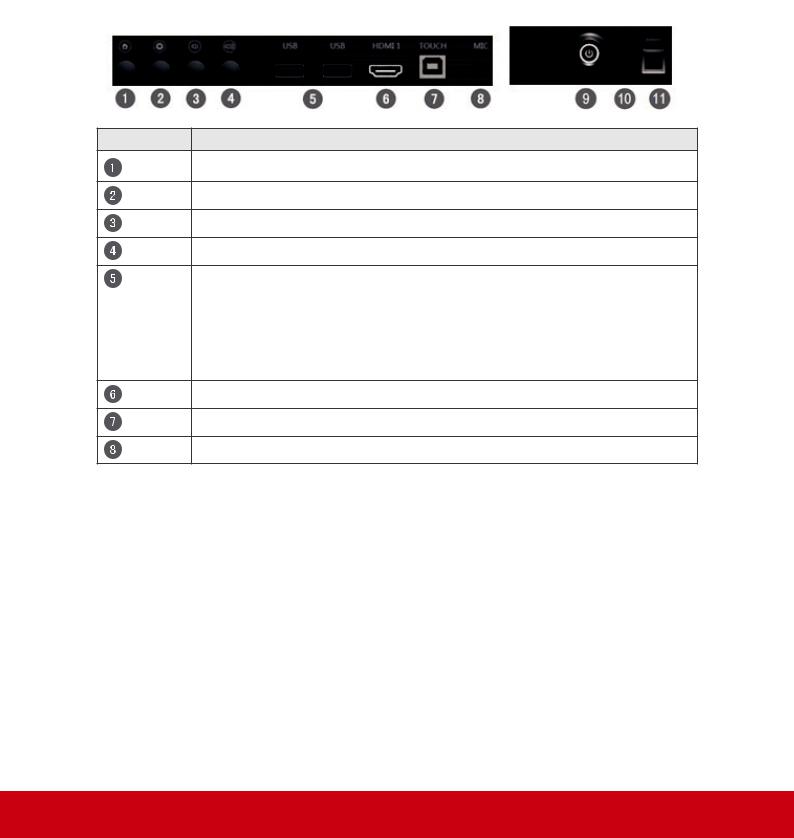
2.1 Control Panel Overview
Item Description
Home button: Back to Embedded player home page.
Menu: Bring up setting menu.
Volume down: Decrease volume
Volume up: Increase volume
Front USB 2.0 *2
Those two USB ports support auto switch function. When switch to a new channel from currently, USB port will direct to the new channel.
Note: You may need to connect the USB touch to your external PC from front/rear touch port.
HDMI 1(ver.1.4) support resolution up to 3840x2160 30Hz.
Touch USB for HDMI1
3.5mm MIC in
5
9Power key:
LED indicator states
RED: Standby mode. Press the power button to power up ViewBoard.
BLUE: Device is in operation. Press and hold the power button to turn off ViewBoard.
RED/BLUE blinking: ViewBaord is in operation but panel is off. Press power button to wake up panel.
Power On: Press power button. LED will turn to blue from red.
Power Off: Press and hold power button for 5s. LED will turn to red from blue.
Panel backlight Off: Press power button shortly. Power LED will blink in blue/red.
10Ambient light sensor / Remote control IR receiver.
IFP6560/IFP6570 support Intelligent Eye Protection. When you turn on the feature, panel backlight will be adjusted according to the ambient light.
Please do not cover ambient light sensor and IR receiver to avoid the features malfunction.
11Fingerprint sensor
The sensor to provide the most secure for biometrics sign-in.
It is able to apply on Windows Hello or MyViewBoard – a Digital cloud Whiteboard designed by ViewSonic.
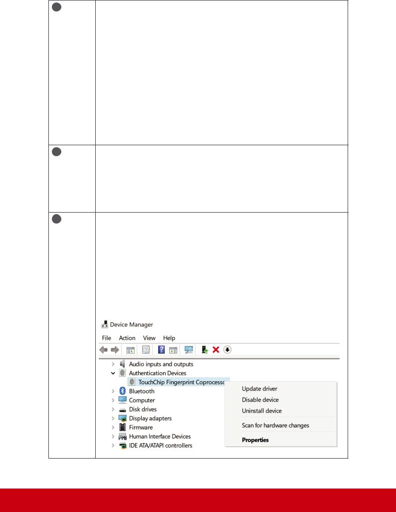
Since Windows Hello is requiring the driver framework by WBF, if you can’t see the fingerprint sign-in option in Windows control panel, you may need to remove and delete fingerprint driver from Windows Device Manager and reinstall driver by Windows update.
[Remove and delete driver from Windows Device Manager]
6
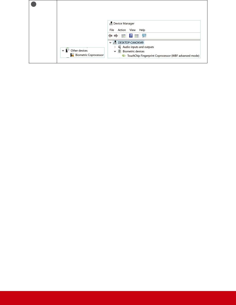
11[Press  , right click on “Biometric Coprocessor” > Update driver
> Search automatically for updated software, internet connection is required]
7
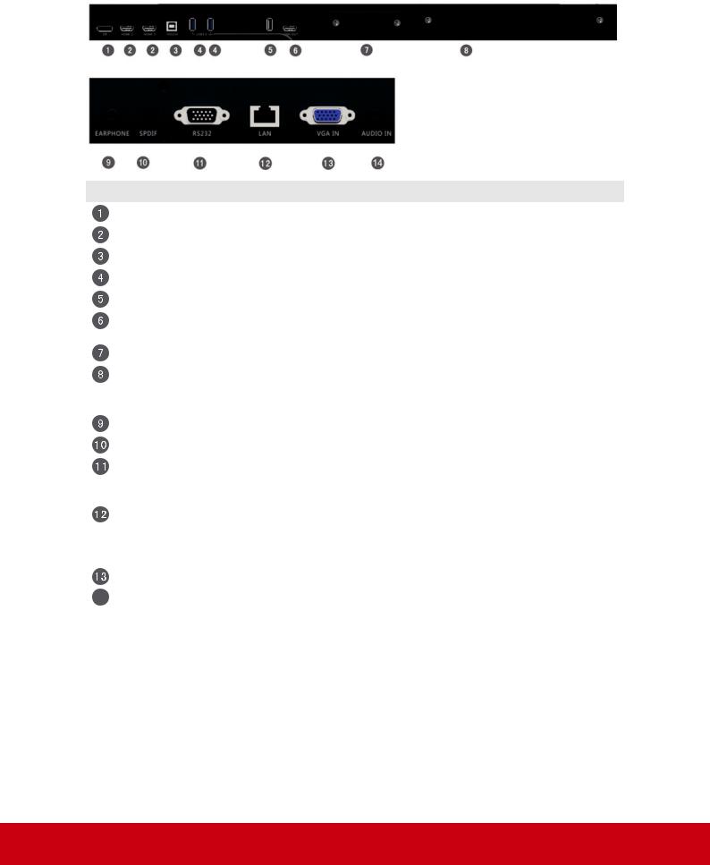
2.2 Terminal Interface Overview
Item |
Description |
|
DP in: DisplayPort (1.2ver). Support resolution up to 3840x2160 60Hz. |
|
HDMI 1.4/2.0 in: Resolution support up to 3840x2160 60Hz. |
|
Touch USB: Touch USB connection for HDMI2/3, DP, and VGA |
|
USB 3.0: For embedded player. |
|
USB 2.0: For embedded player. |
|
HDMI Out: Support 2K/4K image output to another monitor. It only provides |
|
screen mirroring from IFP6560/IFP7560. |
|
SDM: An optional PC module for IFP7560 |
|
OPS: The Open Pluggable Specification PC module slot. The optional PC |
|
module, VPC12-WPO series was optimized for IFP60 ViewBoard. Please |
|
contact local dealer or visit ViewSoinc website for detail information. |
|
3.5mm earphone out |
|
SPDIF out. |
|
RS232: ViewBoard was allowed to control through RS232 device e.g. |
|
Remote PC or a console. Please to get more information from the chart of |
|
RS-232 Protocol. |
|
Ethernet: It supports 10M/100M Ethernet connection by RJ-45 jack. It also |
|
supports remote control by LAN when the standby mode set on “Sleep”. |
|
The control codes are same as RS-232 command code. Please get more |
|
information from the chart of RS-232 Protocol. |
|
VGA in: Support resolution up to 1920x1080. |
14 |
3.5mm Audio in jack for VGA. |
Note: For your safety, please turn off ViewBoard and remove power cord before install/uninstall OPS or SDM
8
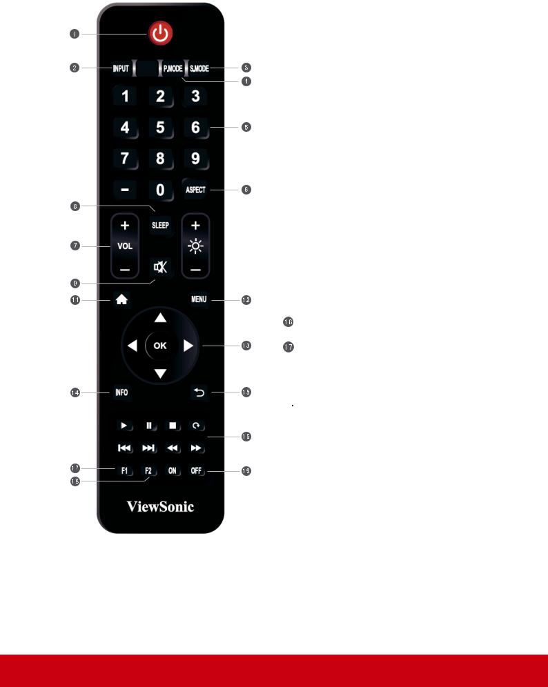
2.3 Remote Control Overview
 Power on/off
 Input Source selection
 Image adjustment menu for DP/HDMI/VGA
 Audio adjustment menu for DP/HDMI/VGA
 Numbers keypad
 Adjust aspect ratio for DP/HDMI/VGA
 Volume +/- 1PC applications
 Display sleep countdown
 Mute
Mute
 Brightness +/- 1
 Back to Embedded player Home screen
 Setting menu
 Up/Down/Right/Left/Ok keys
 Channel information
 Return to previous page
Media control
F1: Screen capture
The files would be saved in the embedded player under the path of System files\Screenshots\
 F2: Screen Freeze
 Power on/off
9
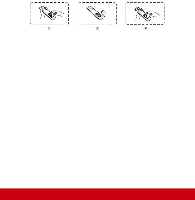
2.4 Inserting Remote Control Batteries
To load the provided batteries into the remote control follow these instructions. We recommend that don’t mix old and new batteries together.
1.Remove the batteries cover on the rear of the remote control.
2.Load two “AAA” batteries in to the battery sink. Please make sure the battery polarities are in correct location.
3.Make sure the batteries are installed neat and correctly, after that put the battery cover back and start to use the remote control.
Warning: There is a risk of explosion if batteries are replaced with the incorrect type.
Note: Always dispose of old batteries in an environmentally friendly way. Contact your local government for more information on how to dispose batteries safely.
10
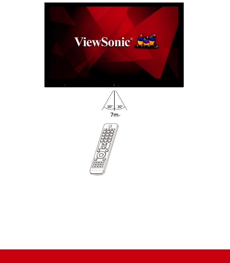
2.5 Remote Control Receiver Range
The working range of the remote control is 7 meter. Make sure there is no object between remote control and IR receiver. You may need to replace a pair of new battery if the remote control workable rage decreases or out of order.
11
3. Set Up Your Display
Warning: For the safety of you and your device, please do not connect to a power supply before the external device is prepared.
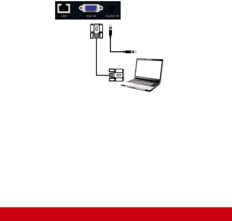
3.1 Connecting an External Device
1.To display video by VGA cable.
•Connect a VGA cable (15-pin) from an external device or PC to the VGA IN port on the ViewBoard.
•Export audio from a PC or media box to audio in by 3.5mm jack.
•Connect a Touch USB cable from PC to display rear Touch USB port.
Audio cable
VGA cable
Computer
Note: Rear Touch USB port is arranged in pair with HDMI2/3, DP and VGA.
12
2.To display video via HDMI cable.
•Connect a HDMI cable from your player or PC to the HDMI port on
ViewBoard.
•Connect a Touch USB cable from PC to ViewBoard Touch port.
Note:
Front Touch USB port is arraged in pair with HDMI1
Rear Touch USB port is arranged in pair with HDMI2/3, DP and VGA.
13
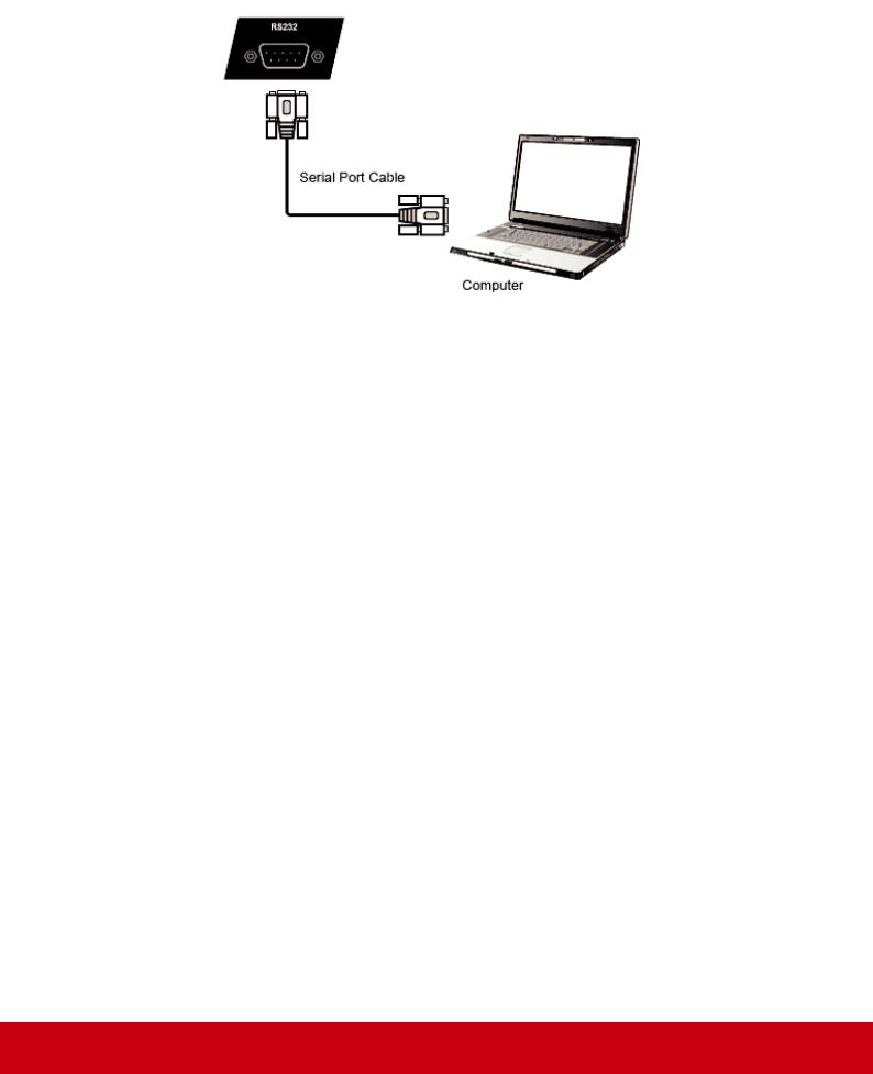
3.2 RS232 Connections
Serial Port Cable
Through RS-232 connection, you could turn on ViewBoard, adjust volume or switch input source from a remote PC or console. ViewSonic also provide an easy-to-use control tool, vController. Please find the introduction and download the SW from ViewSonic website. More information about the remote control connection, please refer the chart of RS-232 Protocol.
https://www.youtube.com/watch?v=0JIvw3IMZjM
14
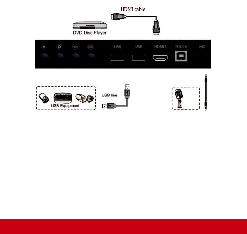
3.3 Connect a USB, HDMI or Media devices
Just like a regular display, it is easy to connect devices on ViewBoard through USB,
HDMI or others.
1.USB: Easy to connect a USB keyboard or mouse without extra settings.
ViewBaord also support a regular USB storage sticker (FAT32 format for embed player). 3rd Wi-Fi adaptor is limited supported. Please contact local service center for more information on technically.
2.HDMI: Support high-resolution signal input for Set-Top-Box, Blu-Ray player or 4K PC. HDR function is not supported on IFP60 series.
3.Mic in for loudspeaker: Plug-in a Mic by 3.5mm jack, ViewBoard will be a loudspeaker for meeting or classroom. The feature doesn’t support audio recording or conference call due to hardware limitation.
Note:
HDMI 1 supports resolution up to 3840x2160 30Hz
HDMI 2/3 supports resolution up to 3840x2160 60Hz
DisplayPort supports resolution up to 3840x2160 60Hz
15
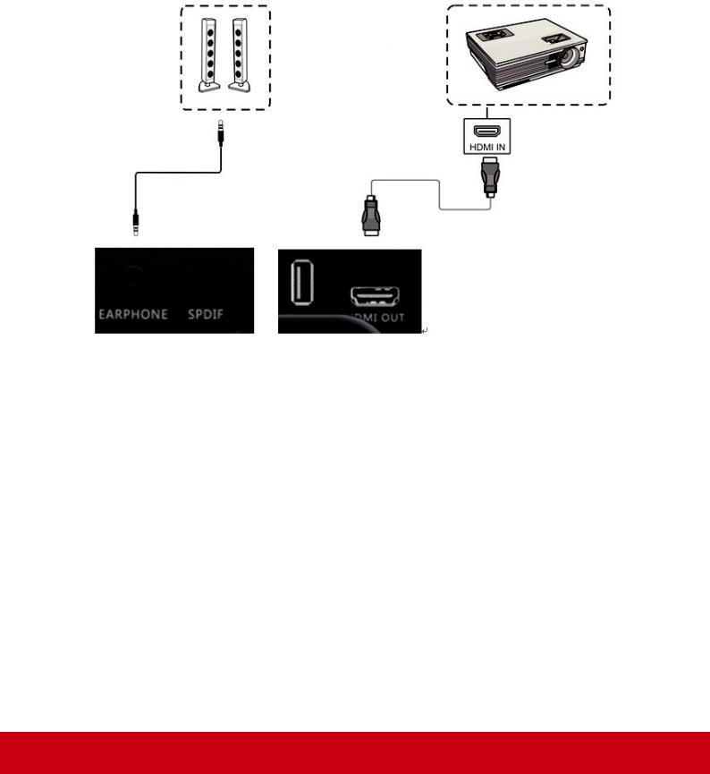
3.4 Video and Audio out connection
Through HDMI out, it’s able to do screen mirroring with audio to a regular monitor or projector. Export image resolution support 1920 x 1080 (2K) and 3840 x 2160 (4K). You could adjust the settings from settings > display > HDMI out from embed player settings menu.
Through earphone out or SPDIF, you could export audio from ViewBoard to an amplifier or speaker.
16
4. ViewBoard Basic Operation
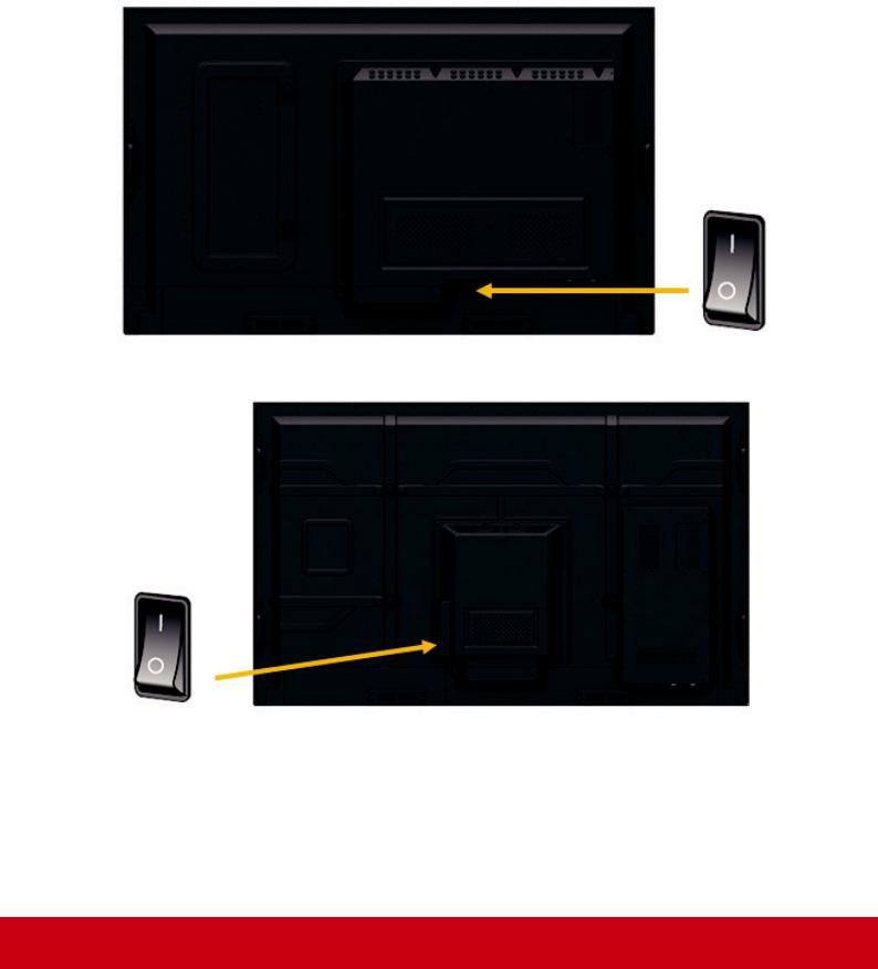
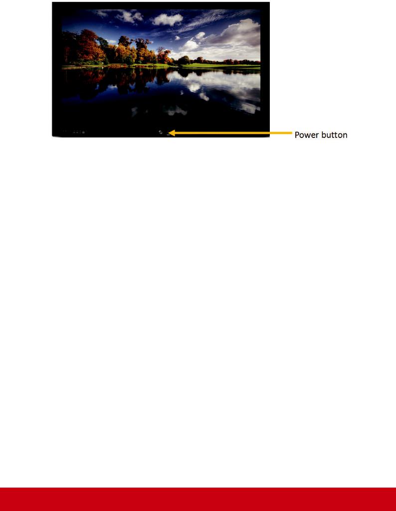
Power on ViewBoard
1.Plug in power cord and turn the AC switch on.
2.Press Power button. Power LED will turn to blue.
IFP6560
IFP7560
17
18
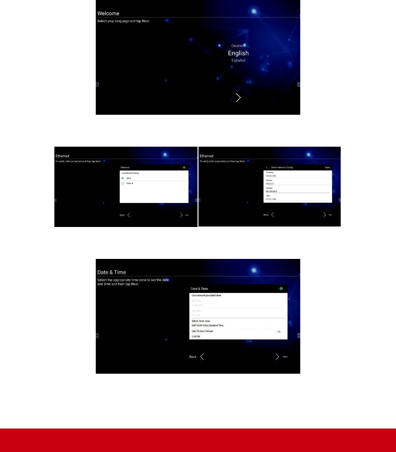
4.1 ViewBoard Launcher screen
Initial setting for Education mode or Corporate mode
ViewBoard will run setup wizard when first power on ViewBoard. Step 1: Select system language.
Step 2: Choose Ethernet connection method. DHCP is for regular network connection. Static IP is for a specific network environment.
Step 3: ViewBoard is able to obtain the accurate date and time from a standard time server. Select the appropriate time zone for your location.
19
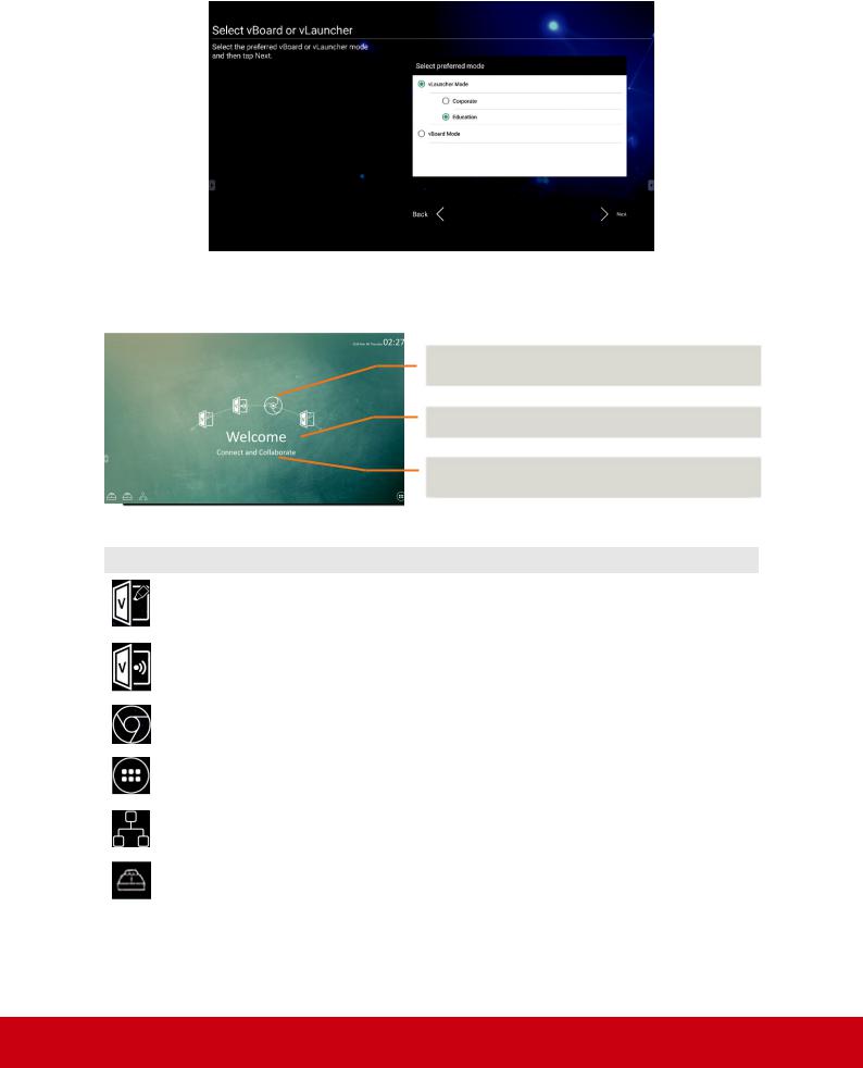
Step 4: Select the preferred launcher theme: vBoard – digital white board or vLauncher mode.
vLauncher for customized welcome screen
Customizable - choose your “top4“ default app
Editable - change your default message
Switchchable - change your launcher theme image
Item |
Description |
|
vBoard |
Click to vBoard software |
|
The icon can be replaced or removed |
||
|
||
|
|
|
ViewBoard |
Click to ViewBoard Cast software |
|
Cast |
The icon can be replaced or removed |
|
|
|
|
Chromium |
Click to enter internet page |
|
The icon can be replaced or removed |
||
|
||
|
|
|
APPs |
Click to enter Embedded Player application management page |
|
|
|
|
Network |
Click to enter Ethernet settings |
|
|
|
|
USB storage |
Click it to open file manager |
|
|
|
20
How to customize the default app:
Step 1: |
Step 2: |
click the “app“ icon to go to the |
long press the preferred app icon |
app listing page |
e.g. WPS and drag to launcher |
|
page |
Step 3:
the chosen app e.g. WPS will be appeared in the launcher as the short-cut to launch the program
If user swipes the main page from right to left, user will see the 2nd page which include other preloaded app and setting.
More app and setting: More introductions in chapter 5
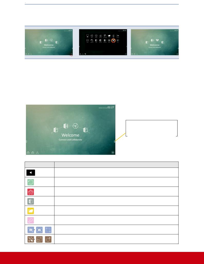
4.2 Tool Bar
Tool bar trigger icon is in the edge of the ViewBoard
Item Description
Extend/Roll back tool bar
Return previous page
Back to embedded player Home page
vBoard
File Manager
Annotation tool
Screen capture: full screen/snipping tool
Others: magnifier / Spotlight
21
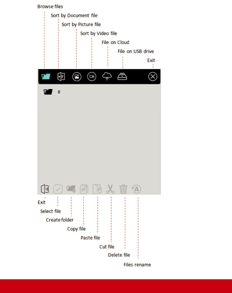
 File Manager
22
 Loading...